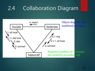
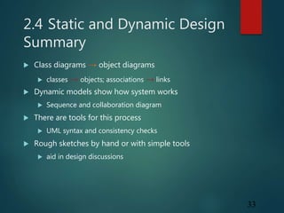
UML (Unified Modeling Language) is a graphical language used to visualize, specify, construct and document software systems. It provides standard terminology and modeling techniques to describe object-oriented systems. Some key UML diagrams include class diagrams, which show the structure and relationships between classes/objects, and sequence diagrams, which illustrate the interactions between objects over time through messages. UML aims to provide a common modeling language that can be used to discuss, document and aid the design of software systems.


![3
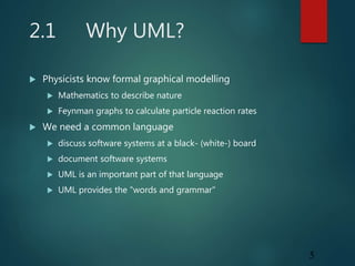
2.1 UML Background
"The Unified Modelling Language (UML) is a graphical
language for visualizing, specifying, constructing, and
documenting the artifacts of a software-intensive system.
The UML offers a standard way to write a systems blueprints,
including conceptual things like business processes
and system functions as well as concrete things such as
programming language statements, database schemas, and
reusable software components."
Grady Booch, Ivar Jacobsen, Jim Rumbaugh
Rational Software
[OMG Unified Modelling Language Specification, Version 1.3, March 2000]](https://image.slidesharecdn.com/basicsofuml-191121035922/85/Basics-of-uml-3-320.jpg)