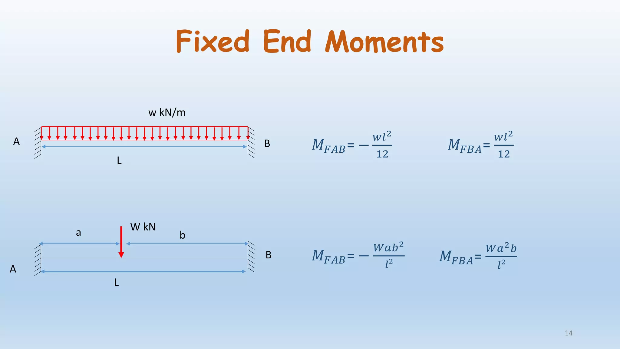
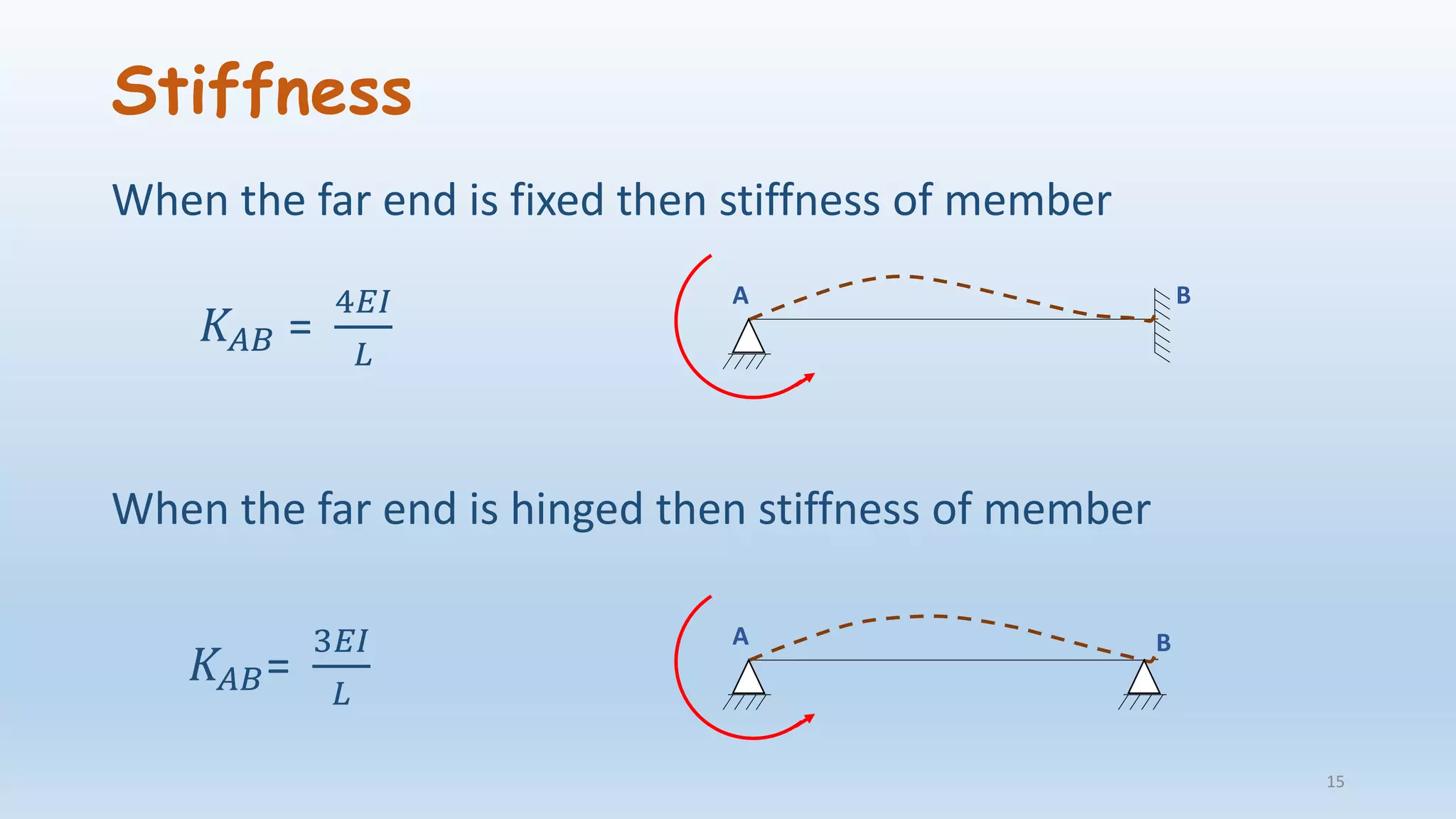
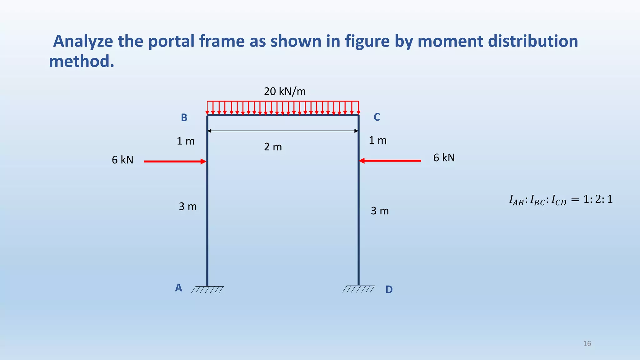
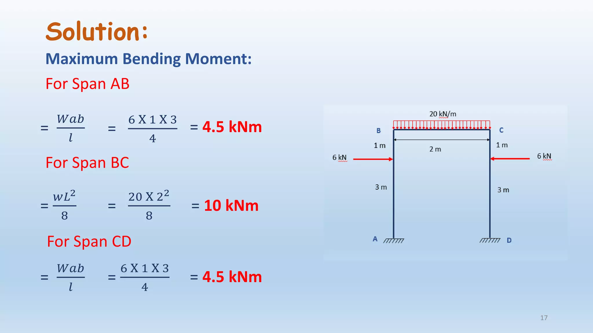
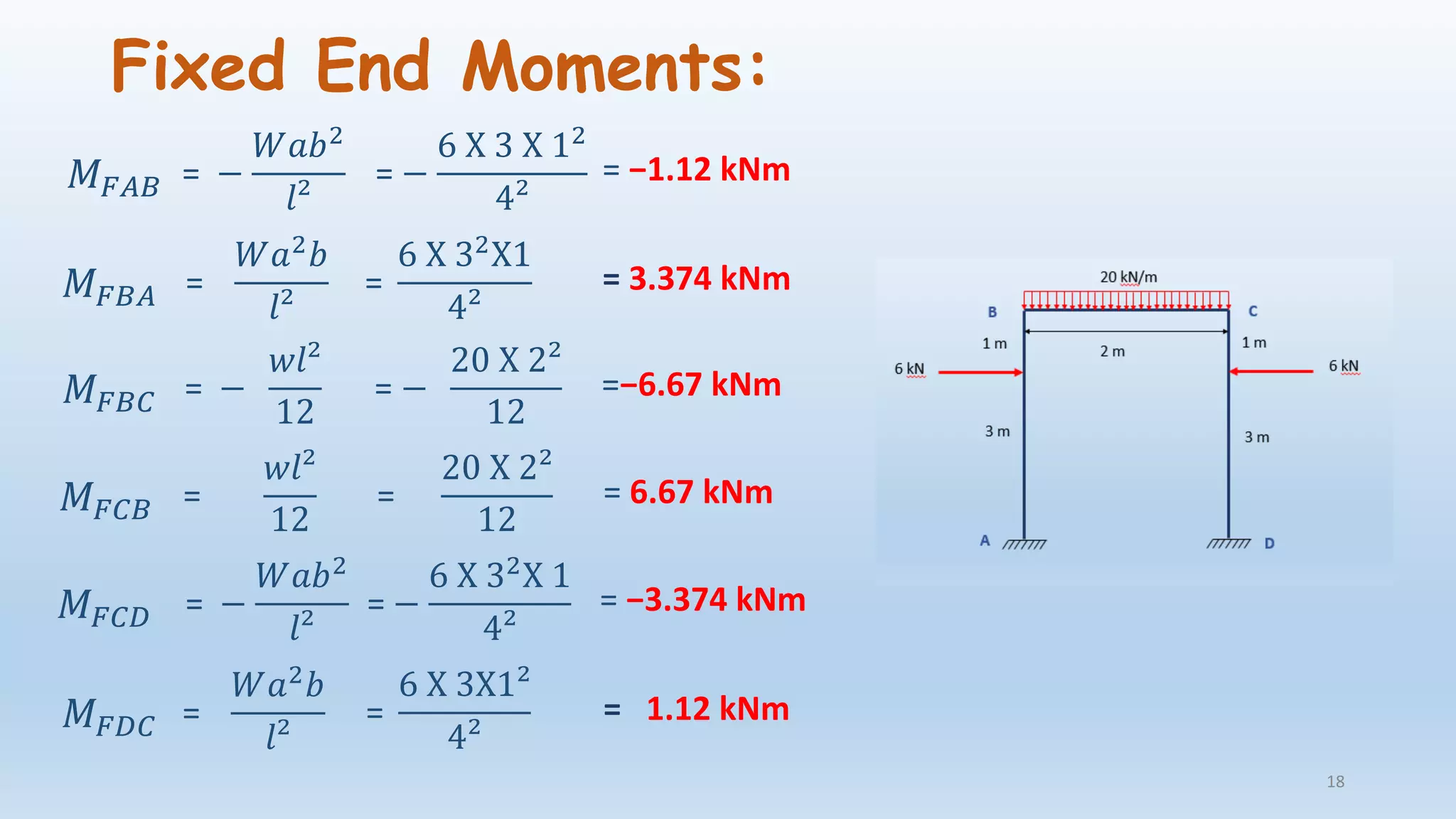
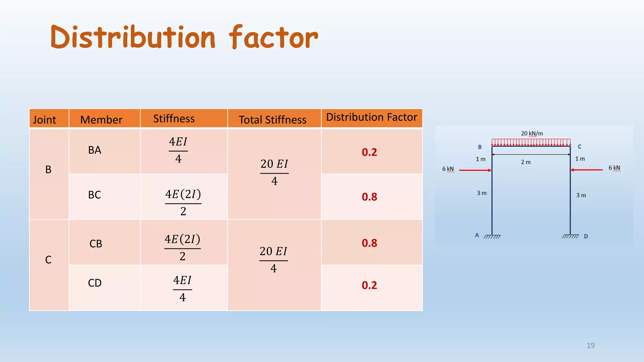
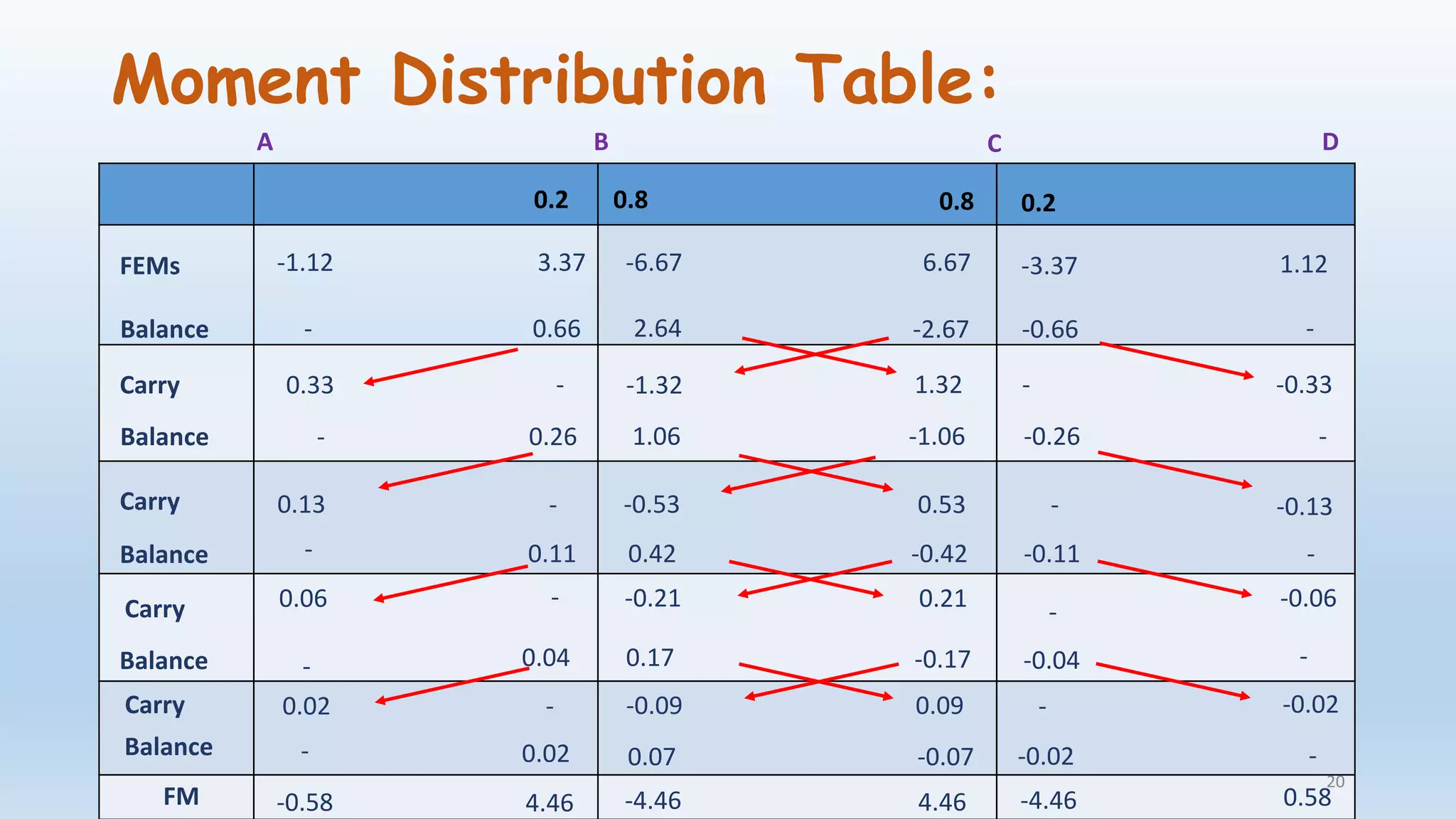
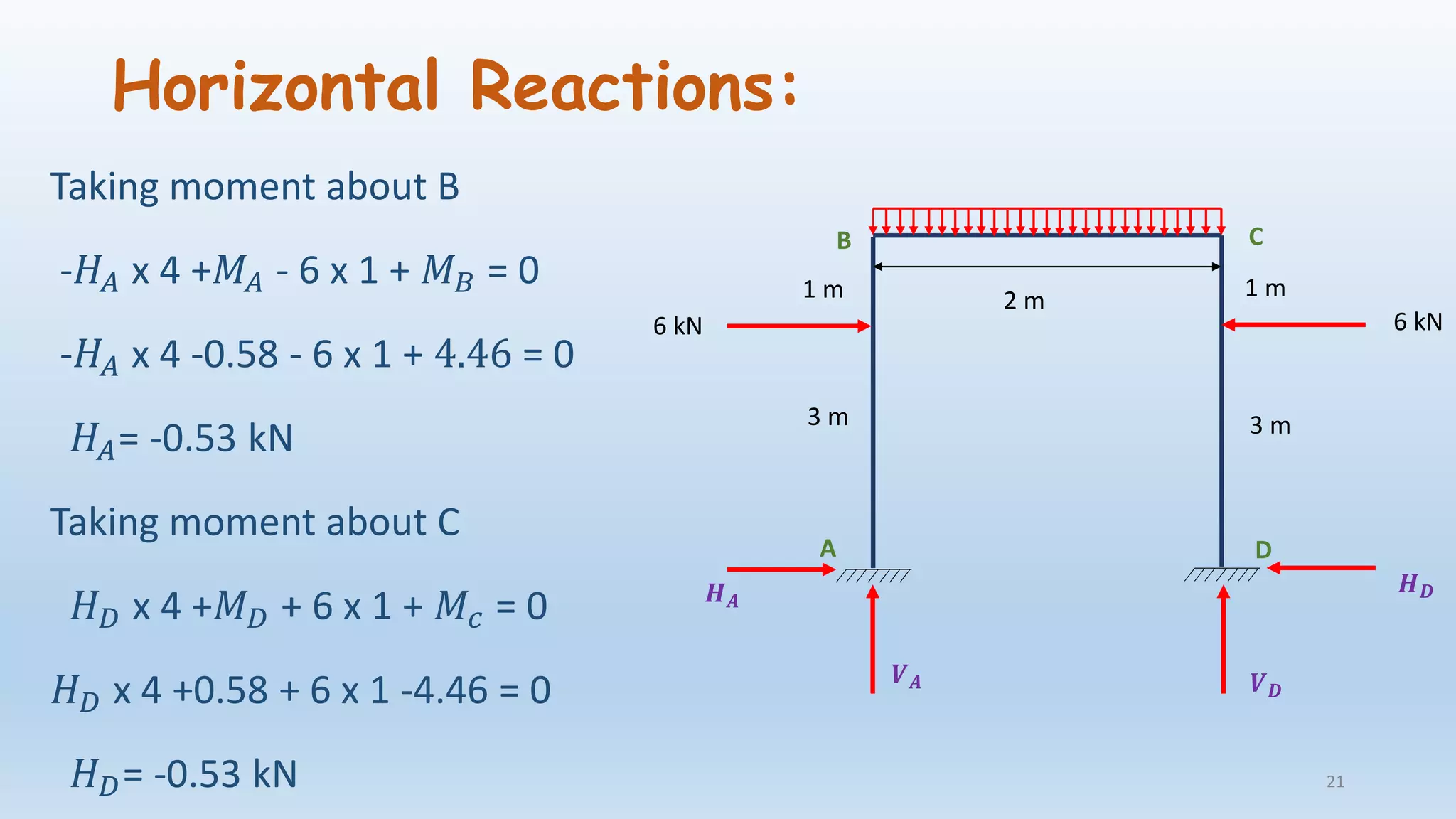
Structural Analysis II
(CE-403)
By
Iqbal Hafeez Khan
Assistant Professor
Department of Civil Engineering
SISTec Gandhi Nagar,Bhopal
Email id- khaniqbalhafeez@gmail.com 1
References:
• C S Reddy, Basic Structural Analysis, Tata McGraw Hill.
• B.C. Punmia , Theory of Structures,Laxmi Publication
• S. Ramamrutham, Theory of Structures,Dhanpat Rai Publication
2
What is Structure?
• A structure is a series of connected, interrelated elements that form
together a system that can resist a series of external load effects
applied to it which includes its own self weight and provide adequate
rigidity.
Courtesy:eyesondeck.typepad.com 3
Important Civil Engineering Structure
Opera House
(Courtesy:Wikipedia)
Taj Mahal
(Courtesy:Wikipedia) 4
Bandra Worli Sea Link
(Courtesy:Wikipedia)
Burj Al Arab
(Courtesy:https://blogs-images.forbes.com)
5
What is Structural Analysis?
• It is a method or tool by which we find out how a
structure or a member of a structure behaves when
subjected to force or combination of forces
• In other words finding out internal forces (axial force,
shear force, moment), stress, strain, deflection etc in a
structure under applied load conditions.
6
Axial force
Compression
7
Tension
Axial force is defined as the force acting along the axis of body. Axial
force can be tension or compression
Shear Force
Shearing forces are unaligned forces pushing one part of a body in one
specific direction and another part of body in the opposite direction.
+ -
8
Bending Moment
Bending moment is the reaction induced in a structural element when
an external force or moment is applied to the element causing the
element to bend.
Sagging Hogging
9
What we have learnt earlier?
• Strain Energy
• Three Moment Theorem
• Moment Distribution Method
• Column Analogy Method
• Slope Deflection Method
• Cable and Arches
• ILD for Determinate Structure
10
Content of the subject
Unit Topic
Unit 1 Moment Distribution Method for sway analysis, Kani’s
method for beams and frame
Unit 2 Plastic analysis of beam and frame
Unit 3
Analysis of tall frames, codal provisions for lateral
loads, approximate analysis of multistorey frames for
vertical and lateral loads
Unit 4 Flexibility and stiffness matrix method
Unit 5 Influence line diagram for indeterminate structures
11
Moment Distribution Method
Step 1- Calculate maximum bending moment
Step 2- Calculate fixed end moments
Step 3- Calculation of distribution factor by calculating stiffness of member
Step 4- Distribute the net fixed end moments at the joints to various
members and carry over moments from the far ends of the same member.
This procedure will be repeated till convergence.
Step 5-Draw the final bending moment diagram for the given loading.
12
Maximum Bending Moment:
𝑤𝐿2
8
w kN/m
W kNa b
𝑊𝑎𝑏
𝐿
L
L
13
Fixed End Moments
w kN/m
W kNa b
L
L
A
A
B
B
𝑀 𝐹𝐴𝐵= −
𝑤𝑙2
12
𝑀 𝐹𝐵𝐴=
𝑤𝑙2
12
𝑀 𝐹𝐴𝐵= −
𝑊𝑎𝑏2
𝑙²
𝑀 𝐹𝐵𝐴=
𝑊𝑎2 𝑏
𝑙²
14
Stiffness
When the far end is fixed then stiffness of member
𝐾𝐴𝐵 =
4𝐸𝐼
𝐿
When the far end is hinged then stiffness of member
𝐾𝐴𝐵=
3𝐸𝐼
𝐿
15
A B
A B
Analyze the portal frame as shown in figure by moment distribution
method.
20 kN/m
6 kN6 kN
2 m1 m
3 m 3 m
1 m
𝐼𝐴𝐵: 𝐼 𝐵𝐶: 𝐼 𝐶𝐷 = 1: 2: 1
B
A
C
D
16
Solution:
Maximum Bending Moment:
For Span AB
17
=
𝑊𝑎𝑏
𝑙
=
6 X 1 X 3
4
= 4.5 kNm
For Span BC
=
𝑤𝐿2
8
=
20 X 22
8
= 10 kNm
For Span CD
=
𝑊𝑎𝑏
𝑙
=
6 X 1 X 3
4
= 4.5 kNm
Fixed End Moments:
18
𝑀 𝐹𝐴𝐵 = −
𝑊𝑎𝑏2
𝑙²
= −
6 X 3 X 12
4²
= −1.12 kNm
𝑀 𝐹𝐵𝐴 =
𝑊𝑎2
𝑏
𝑙²
=
6 X 32
X1
4²
= 3.374 kNm
𝑀 𝐹𝐵𝐶 = −
𝑤𝑙²
12
= −
20 X 2²
12
=−6.67 kNm
𝑀 𝐹𝐶𝐵 =
𝑤𝑙²
12
=
20 X 2²
12
= 6.67 kNm
𝑀 𝐹𝐶𝐷 = −
𝑊𝑎𝑏2
𝑙²
= −
6 X 32X 1
4²
= −3.374 kNm
𝑀 𝐹𝐷𝐶 =
𝑊𝑎2 𝑏
𝑙²
=
6 X 3X1²
4²
= 1.12 kNm
Distribution factor
Joint Member Stiffness Total Stiffness Distribution Factor
B
BA
BC
4𝐸𝐼
4
4𝐸 2𝐼
2
20 𝐸𝐼
4
0.2
0.8
C
CB
CD
4𝐸 2𝐼
2
4𝐸𝐼
4
20 𝐸𝐼
4
0.8
0.2
19
Moment Distribution Table:
0.2 0.8 0.8 0.2
FEMs -1.12 3.37 -6.67 6.67 -3.37 1.12
Balance - 0.66 2.64 -2.67 -0.66 -
Carry 0.33 - -1.32 1.32 - -0.33
Balance - 0.26 1.06 -1.06 -0.26 -
Carry 0.13 - -0.53 0.53 - -0.13
Balance - 0.11 0.42 -0.42 -0.11 -
Carry 0.06 - 0.21-0.21 -0.06
-
Balance - 0.04 0.17 -0.17 -0.04
Carry
-
0.02 - -0.09 0.09 - -0.02
Balance - 0.02 0.07 -0.07 -0.02 -
-0.58 4.46 -4.46 4.46 -4.46 0.58FM
A B C D
20
Horizontal Reactions:
Taking moment about B
-𝐻𝐴 x 4 +𝑀𝐴 - 6 x 1 + 𝑀 𝐵 = 0
-𝐻𝐴 x 4 -0.58 - 6 x 1 + 4.46 = 0
𝐻𝐴= -0.53 kN
Taking moment about C
𝐻 𝐷 x 4 +𝑀 𝐷 + 6 x 1 + 𝑀𝑐 = 0
𝐻 𝐷 x 4 +0.58 + 6 x 1 -4.46 = 0
𝐻 𝐷= -0.53 kN
6 kN6 kN
2 m1 m
3 m 3 m
1 m
𝑯 𝑨
𝑯 𝑫
𝑽 𝑨 𝑽 𝑫
A
B C
D
21
Summation of Horizontal Force
= 𝐻𝐴 − 𝐻 𝐷
=-0.53 – (-0.53)
= 0
22
10 kNm
4.5 kNm 4.5 kNm
4.46 kNm 4.46 kNm
0.58 kNm 0.58 kNm
Bending Moment Diagram
23
A
B C
D
1.18

Lecture 1 (Introduction to Structural Analysis II)

  • 1.
    Structural Analysis II (CE-403) By IqbalHafeez Khan Assistant Professor Department of Civil Engineering SISTec Gandhi Nagar,Bhopal Email id- khaniqbalhafeez@gmail.com 1
  • 2.
    References: • C SReddy, Basic Structural Analysis, Tata McGraw Hill. • B.C. Punmia , Theory of Structures,Laxmi Publication • S. Ramamrutham, Theory of Structures,Dhanpat Rai Publication 2
  • 3.
    What is Structure? •A structure is a series of connected, interrelated elements that form together a system that can resist a series of external load effects applied to it which includes its own self weight and provide adequate rigidity. Courtesy:eyesondeck.typepad.com 3
  • 4.
    Important Civil EngineeringStructure Opera House (Courtesy:Wikipedia) Taj Mahal (Courtesy:Wikipedia) 4
  • 5.
    Bandra Worli SeaLink (Courtesy:Wikipedia) Burj Al Arab (Courtesy:https://blogs-images.forbes.com) 5
  • 6.
    What is StructuralAnalysis? • It is a method or tool by which we find out how a structure or a member of a structure behaves when subjected to force or combination of forces • In other words finding out internal forces (axial force, shear force, moment), stress, strain, deflection etc in a structure under applied load conditions. 6
  • 7.
    Axial force Compression 7 Tension Axial forceis defined as the force acting along the axis of body. Axial force can be tension or compression
  • 8.
    Shear Force Shearing forcesare unaligned forces pushing one part of a body in one specific direction and another part of body in the opposite direction. + - 8
  • 9.
    Bending Moment Bending momentis the reaction induced in a structural element when an external force or moment is applied to the element causing the element to bend. Sagging Hogging 9
  • 10.
    What we havelearnt earlier? • Strain Energy • Three Moment Theorem • Moment Distribution Method • Column Analogy Method • Slope Deflection Method • Cable and Arches • ILD for Determinate Structure 10
  • 11.
    Content of thesubject Unit Topic Unit 1 Moment Distribution Method for sway analysis, Kani’s method for beams and frame Unit 2 Plastic analysis of beam and frame Unit 3 Analysis of tall frames, codal provisions for lateral loads, approximate analysis of multistorey frames for vertical and lateral loads Unit 4 Flexibility and stiffness matrix method Unit 5 Influence line diagram for indeterminate structures 11
  • 12.
    Moment Distribution Method Step1- Calculate maximum bending moment Step 2- Calculate fixed end moments Step 3- Calculation of distribution factor by calculating stiffness of member Step 4- Distribute the net fixed end moments at the joints to various members and carry over moments from the far ends of the same member. This procedure will be repeated till convergence. Step 5-Draw the final bending moment diagram for the given loading. 12
  • 13.
    Maximum Bending Moment: 𝑤𝐿2 8 wkN/m W kNa b 𝑊𝑎𝑏 𝐿 L L 13
  • 14.
    Fixed End Moments wkN/m W kNa b L L A A B B 𝑀 𝐹𝐴𝐵= − 𝑤𝑙2 12 𝑀 𝐹𝐵𝐴= 𝑤𝑙2 12 𝑀 𝐹𝐴𝐵= − 𝑊𝑎𝑏2 𝑙² 𝑀 𝐹𝐵𝐴= 𝑊𝑎2 𝑏 𝑙² 14
  • 15.
    Stiffness When the farend is fixed then stiffness of member 𝐾𝐴𝐵 = 4𝐸𝐼 𝐿 When the far end is hinged then stiffness of member 𝐾𝐴𝐵= 3𝐸𝐼 𝐿 15 A B A B
  • 16.
    Analyze the portalframe as shown in figure by moment distribution method. 20 kN/m 6 kN6 kN 2 m1 m 3 m 3 m 1 m 𝐼𝐴𝐵: 𝐼 𝐵𝐶: 𝐼 𝐶𝐷 = 1: 2: 1 B A C D 16
  • 17.
    Solution: Maximum Bending Moment: ForSpan AB 17 = 𝑊𝑎𝑏 𝑙 = 6 X 1 X 3 4 = 4.5 kNm For Span BC = 𝑤𝐿2 8 = 20 X 22 8 = 10 kNm For Span CD = 𝑊𝑎𝑏 𝑙 = 6 X 1 X 3 4 = 4.5 kNm
  • 18.
    Fixed End Moments: 18 𝑀𝐹𝐴𝐵 = − 𝑊𝑎𝑏2 𝑙² = − 6 X 3 X 12 4² = −1.12 kNm 𝑀 𝐹𝐵𝐴 = 𝑊𝑎2 𝑏 𝑙² = 6 X 32 X1 4² = 3.374 kNm 𝑀 𝐹𝐵𝐶 = − 𝑤𝑙² 12 = − 20 X 2² 12 =−6.67 kNm 𝑀 𝐹𝐶𝐵 = 𝑤𝑙² 12 = 20 X 2² 12 = 6.67 kNm 𝑀 𝐹𝐶𝐷 = − 𝑊𝑎𝑏2 𝑙² = − 6 X 32X 1 4² = −3.374 kNm 𝑀 𝐹𝐷𝐶 = 𝑊𝑎2 𝑏 𝑙² = 6 X 3X1² 4² = 1.12 kNm
  • 19.
    Distribution factor Joint MemberStiffness Total Stiffness Distribution Factor B BA BC 4𝐸𝐼 4 4𝐸 2𝐼 2 20 𝐸𝐼 4 0.2 0.8 C CB CD 4𝐸 2𝐼 2 4𝐸𝐼 4 20 𝐸𝐼 4 0.8 0.2 19
  • 20.
    Moment Distribution Table: 0.20.8 0.8 0.2 FEMs -1.12 3.37 -6.67 6.67 -3.37 1.12 Balance - 0.66 2.64 -2.67 -0.66 - Carry 0.33 - -1.32 1.32 - -0.33 Balance - 0.26 1.06 -1.06 -0.26 - Carry 0.13 - -0.53 0.53 - -0.13 Balance - 0.11 0.42 -0.42 -0.11 - Carry 0.06 - 0.21-0.21 -0.06 - Balance - 0.04 0.17 -0.17 -0.04 Carry - 0.02 - -0.09 0.09 - -0.02 Balance - 0.02 0.07 -0.07 -0.02 - -0.58 4.46 -4.46 4.46 -4.46 0.58FM A B C D 20
  • 21.
    Horizontal Reactions: Taking momentabout B -𝐻𝐴 x 4 +𝑀𝐴 - 6 x 1 + 𝑀 𝐵 = 0 -𝐻𝐴 x 4 -0.58 - 6 x 1 + 4.46 = 0 𝐻𝐴= -0.53 kN Taking moment about C 𝐻 𝐷 x 4 +𝑀 𝐷 + 6 x 1 + 𝑀𝑐 = 0 𝐻 𝐷 x 4 +0.58 + 6 x 1 -4.46 = 0 𝐻 𝐷= -0.53 kN 6 kN6 kN 2 m1 m 3 m 3 m 1 m 𝑯 𝑨 𝑯 𝑫 𝑽 𝑨 𝑽 𝑫 A B C D 21
  • 22.
    Summation of HorizontalForce = 𝐻𝐴 − 𝐻 𝐷 =-0.53 – (-0.53) = 0 22
  • 23.
    10 kNm 4.5 kNm4.5 kNm 4.46 kNm 4.46 kNm 0.58 kNm 0.58 kNm Bending Moment Diagram 23 A B C D 1.18