Week 1 –Lecture 1
Lecture Outline
Introduction to Moment Distribution Method
Important terminologies
Examples - Beam
3.
Moment Distribution Method
•Moment distribution method was developed by Hardy Cross
and formally presented in 1930.
• It is a displacement method of analysis.
• The degree of accuracy of the results obtained by this
method depends on the number of successive
approximations or iteration process.
4.
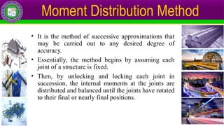
• It isthe method of successive approximations that
may be carried out to any desired degree of
accuracy.
• Essentially, the method begins by assuming each
joint of a structure is fixed.
• Then, by unlocking and locking each joint in
succession, the internal moments at the joints are
distributed and balanced until the joints have rotated
to their final or nearly final positions.
Moment Distribution Method
5.
Moment Distribution Method
IMPORTANTTERMINOLOGIES
Certain definitions and concepts which will be used in moment distribution
method are discussed first:
1. Sign Convention: Clockwise moments on the member are considered
positive, and counterclockwise moments are negative.
2. Fixed End Moments (FEM): The moments at the walls or fixed joints of
a loaded member are called Fixed End Moments. These can be
calculated from already developed formulae (formulae can be found on
inside of back cover of R.C. Hibbeler).
3. Member Stiffness Factor (K): It is the stiffness coefficient depending on
the shape and length of the member, K = I/L
6.
Moment Distribution Method
Stiffnessmay also be defined as the force required to produce
unit displacement. Consider the beam as shown:
Application of moment M causes the end A to rotate through an angle θA.
The relationship between M and θA is:
M = θA
Where K = [Far end fixed]
It can be defined as the amount of moment M required to rotate the end A of
the beam by 1 radian.
If far end is hinge/ roller then K =
7.
Moment Distribution Method
4.Joint Stiffness Factor: The total stiffness factor at the joint is the sum of
the member stiffness factors at the joint.
5. Distribution Factor (DF): This factor shows that how much moment will
be distributed to each side of the support.
D.F. =
D.F. = 1 for hinge support or roller support at the end of the beam
D.F. = 1 for intermediate support with cantilever on one end
D.F. = 0 for fixed end of the beam
6. Carry-over Factor (COF): It represents that how much moment will be
carried over from one end of the beam to the other end (farther end). It is
taken as ½ for a beam with far end fixed.
8.
Moment Distribution Method
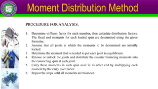
PROCEDUREFOR ANALYSIS:
1. Determine stiffness factor for each member, then calculate distribution factors.
The fixed end moments for each loaded span are determined using the given
formulae.
2. Assume that all joints at which the moments to be determined are initially
locked.
3. Determine the moment that is needed to put each joint in equilibrium.
4. Release or unlock the joints and distribute the counter balancing moments into
the connecting span at each joint.
5. Carry these moments in each span over to its other end by multiplying each
moment by the carry over factor.
6. Repeat the steps until all moments are balanced.


![Moment Distribution Method
Stiffness may also be defined as the force required to produce
unit displacement. Consider the beam as shown:
Application of moment M causes the end A to rotate through an angle θA.
The relationship between M and θA is:
M = θA
Where K = [Far end fixed]
It can be defined as the amount of moment M required to rotate the end A of
the beam by 1 radian.
If far end is hinge/ roller then K =](https://image.slidesharecdn.com/week1-lecture1momentdistributionmethod-250427165829-f07e6a9b/85/Week-1-Lecture-1-Moment-Distribution-Method-pptx-6-320.jpg)