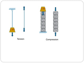
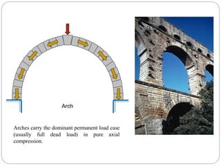
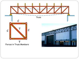
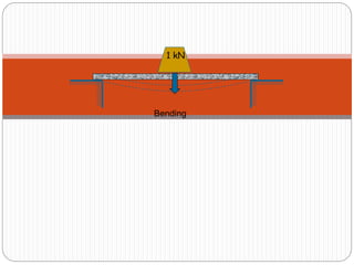
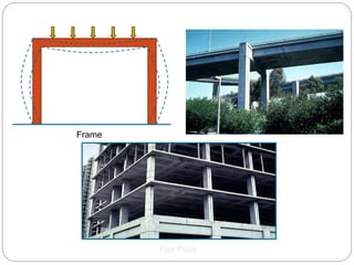
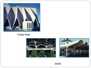
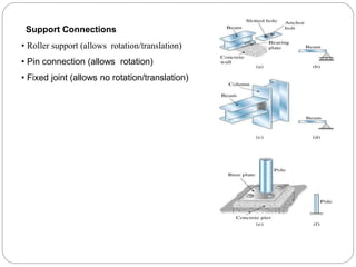
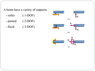
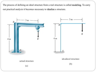
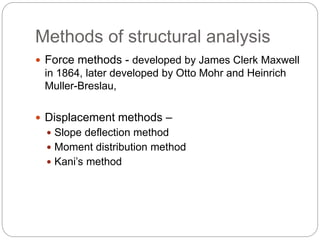
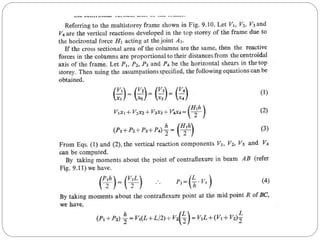
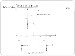
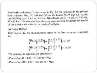
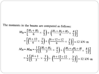
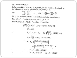
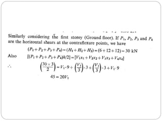
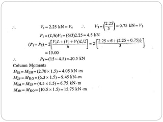
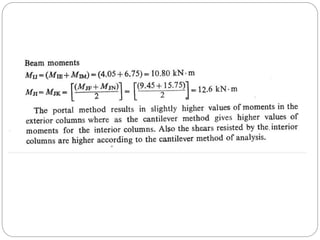
By
Prof SenthilPandian M
Analysis of building frames
Introduction
Structural engineering projects can be divided into 4 stages.
1. Planning phase
• Material
• Structural form
• Loads
2. Analysis
3. Design
4. Construction
The design of a structure involves many considerations, among which are 4 major
objectives that must be satisfied.
1) Safety (the structure must carry loads safely)
2) Economy (the stucture should be economical in material and overall costs)
3) Utility (the structure must meet the performance requirement)
4) Beauty (the stucture should have a good performance)
Therefore, the purpose of structural analysis is to determine the reactions, internal forces
and deformations at any point of a given structure caused by applied loads and forces.
Types of Structural forms
• Tension and Compression structures
• Flexural beam and frame structures (load carrying is achieved by bending)
• Surface structures (load carrying is by membrane action)
1 kN
Compression
1 kN
Tension
Tensile Failure Compressive Failure
Strength : Ability to withstand a given stress without failure. Depends on type of material
and type of force (tension or compression).
Stiffness : Property related to deformation. Stiffer structural elements deform less under
the same applied load. Stiffness depends on type of material (E), structural shape, and
structural configuration.Two main types; Axial stiffness and Bending stiffness.
Important Structural Properties
Stiffest
Stiffer
Stiff
Arch
Arches carry the dominant permanent load case
(usually full dead load) in pure axial
compression.
Truss
C
T
C
C
T
Forces in Truss Members
1 kN
Bending
Frame
Flat Plate
Folded Plate
Shells
Support Connections
• Roller support (allows rotation/translation)
• Pin connection (allows rotation)
• Fixed joint (allows no rotation/translation)
A beam have a variety of supports.
- roller ( 1-DOF)
- pinned ( 2-DOF)
- fixed ( 3-DOF)
The process of defining an ideal structure from a real structure is called modeling. To carry
out practical analysis it becomes necessary to idealize a structure.
18
A beam have a variety of loads.
- point loads
- distributed loads
- applied moments
A beam can be classified as statically determinate
beam, which means that it can be solved using
equilibrium equations, or it is ...
A beam can be classified as statically indeterminate
beam, which can not be solved with equilibrium
equations. It requires a compatibility condition.
Methods of structural analysis
 Force methods - developed by James Clerk Maxwell
in 1864, later developed by Otto Mohr and Heinrich
Muller-Breslau,
 Displacement methods –
 Slope deflection method
 Moment distribution method
 Kani’s method
Analyse building frames
1. Approximate methods for vertical loads.
2. Cantilever method for horizontal loads.
3. Portal method for horizontal loads.
Substitute frame method
 The moments carried from floor to floor through
columns are very small as compared to the beam
moments; therefore, the moments in one floor have
negligible effect on the moments on the floors above
and below. Therefore, in this method, the analysis of
the multi-storeyed frames is carried out by taking one
floor at a time. Each floor is taken with columns above
and below fixed at far ends, and the moments and
shears are calculated in beams and columns.
 The method is very effective in analyzing any framed
structure under vertical loadings
 Motivation talk has to be given to the student
regarding placements in the various fields.
Example structural design concrete building,
Steel structure, evaluation of building etc.,
 At least one or two per semester and all the
student from the school must attended it.
Bending Moment in Columns
Cont.,
Analysis of Multistory frames
subjected to horizontal load
 Height to least lateral dimension greater than 2.
 Load due to Wind
 Seismic forces
 Unsymmetrical building
 Geometric
 Plan
 Mass etc.,
Moment and forces
 Portal method
 Cantilever method
Portal Method
Cantilever method
Static and dynamic loading of structures.pptx

Static and dynamic loading of structures.pptx

  • 1.
  • 2.
  • 3.
    Structural engineering projectscan be divided into 4 stages. 1. Planning phase • Material • Structural form • Loads 2. Analysis 3. Design 4. Construction The design of a structure involves many considerations, among which are 4 major objectives that must be satisfied. 1) Safety (the structure must carry loads safely) 2) Economy (the stucture should be economical in material and overall costs) 3) Utility (the structure must meet the performance requirement) 4) Beauty (the stucture should have a good performance)
  • 4.
    Therefore, the purposeof structural analysis is to determine the reactions, internal forces and deformations at any point of a given structure caused by applied loads and forces. Types of Structural forms • Tension and Compression structures • Flexural beam and frame structures (load carrying is achieved by bending) • Surface structures (load carrying is by membrane action)
  • 5.
  • 6.
  • 7.
    Strength : Abilityto withstand a given stress without failure. Depends on type of material and type of force (tension or compression). Stiffness : Property related to deformation. Stiffer structural elements deform less under the same applied load. Stiffness depends on type of material (E), structural shape, and structural configuration.Two main types; Axial stiffness and Bending stiffness. Important Structural Properties
  • 8.
  • 10.
    Arch Arches carry thedominant permanent load case (usually full dead load) in pure axial compression.
  • 11.
  • 12.
  • 13.
  • 14.
  • 15.
    Support Connections • Rollersupport (allows rotation/translation) • Pin connection (allows rotation) • Fixed joint (allows no rotation/translation)
  • 16.
    A beam havea variety of supports. - roller ( 1-DOF) - pinned ( 2-DOF) - fixed ( 3-DOF)
  • 17.
    The process ofdefining an ideal structure from a real structure is called modeling. To carry out practical analysis it becomes necessary to idealize a structure.
  • 18.
    18 A beam havea variety of loads. - point loads - distributed loads - applied moments
  • 19.
    A beam canbe classified as statically determinate beam, which means that it can be solved using equilibrium equations, or it is ...
  • 20.
    A beam canbe classified as statically indeterminate beam, which can not be solved with equilibrium equations. It requires a compatibility condition.
  • 21.
    Methods of structuralanalysis  Force methods - developed by James Clerk Maxwell in 1864, later developed by Otto Mohr and Heinrich Muller-Breslau,  Displacement methods –  Slope deflection method  Moment distribution method  Kani’s method
  • 22.
    Analyse building frames 1.Approximate methods for vertical loads. 2. Cantilever method for horizontal loads. 3. Portal method for horizontal loads.
  • 23.
    Substitute frame method The moments carried from floor to floor through columns are very small as compared to the beam moments; therefore, the moments in one floor have negligible effect on the moments on the floors above and below. Therefore, in this method, the analysis of the multi-storeyed frames is carried out by taking one floor at a time. Each floor is taken with columns above and below fixed at far ends, and the moments and shears are calculated in beams and columns.  The method is very effective in analyzing any framed structure under vertical loadings
  • 43.
     Motivation talkhas to be given to the student regarding placements in the various fields. Example structural design concrete building, Steel structure, evaluation of building etc.,  At least one or two per semester and all the student from the school must attended it.
  • 47.
  • 48.
  • 49.
    Analysis of Multistoryframes subjected to horizontal load  Height to least lateral dimension greater than 2.  Load due to Wind  Seismic forces  Unsymmetrical building  Geometric  Plan  Mass etc.,
  • 50.
    Moment and forces Portal method  Cantilever method
  • 51.
  • 56.