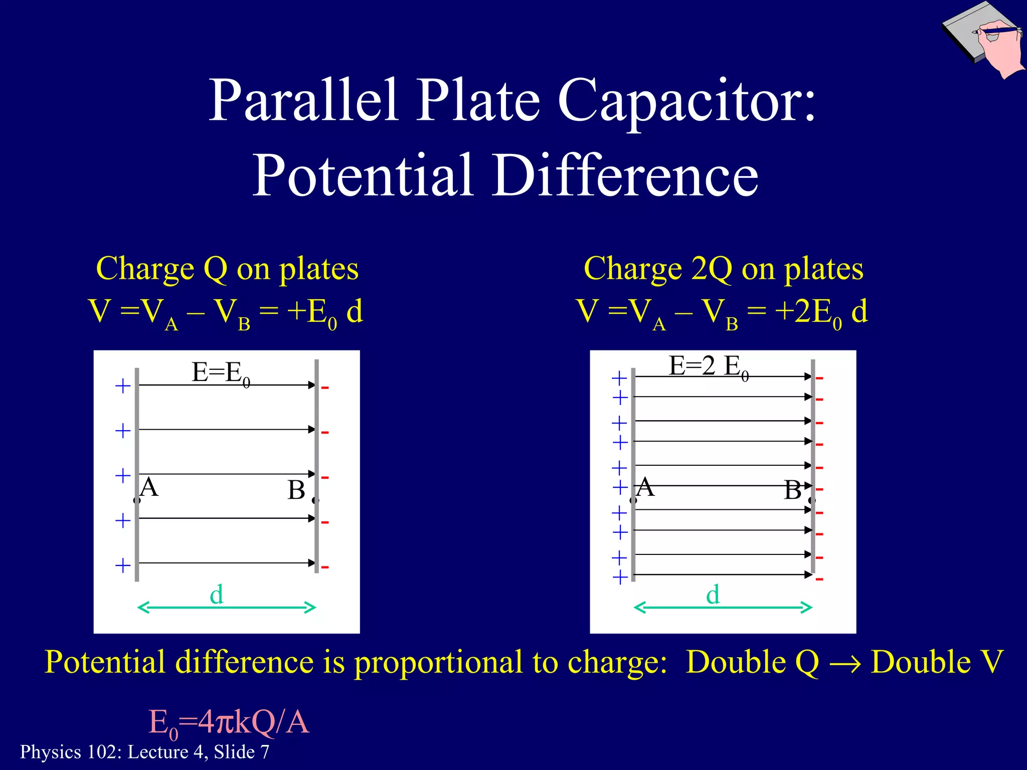
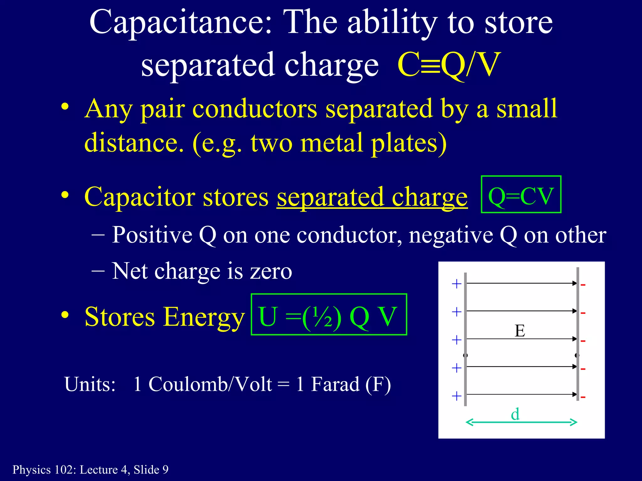
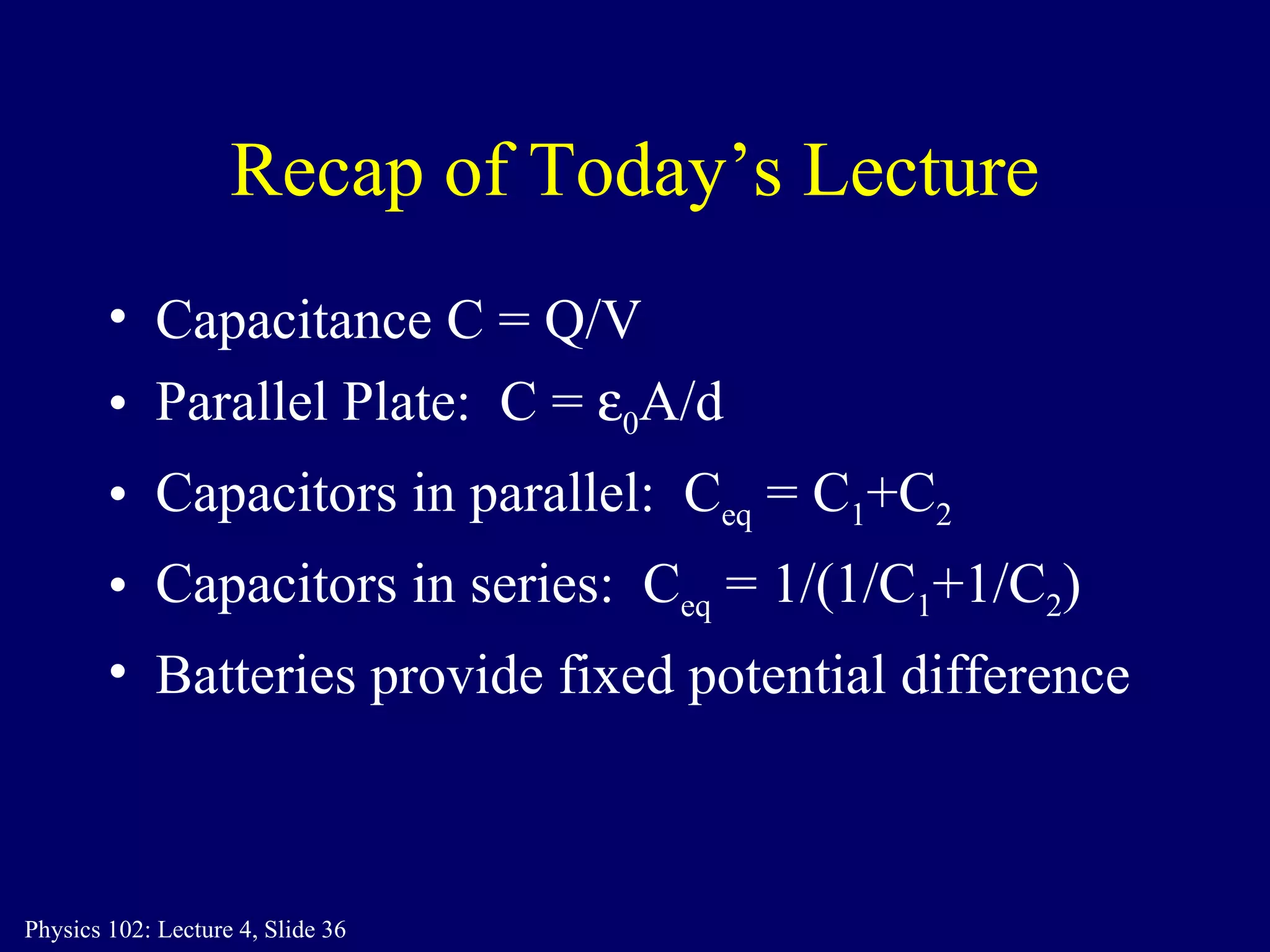
1. The document discusses capacitors and capacitance, including parallel plate capacitors. It defines capacitance as the ability to store separated charge.
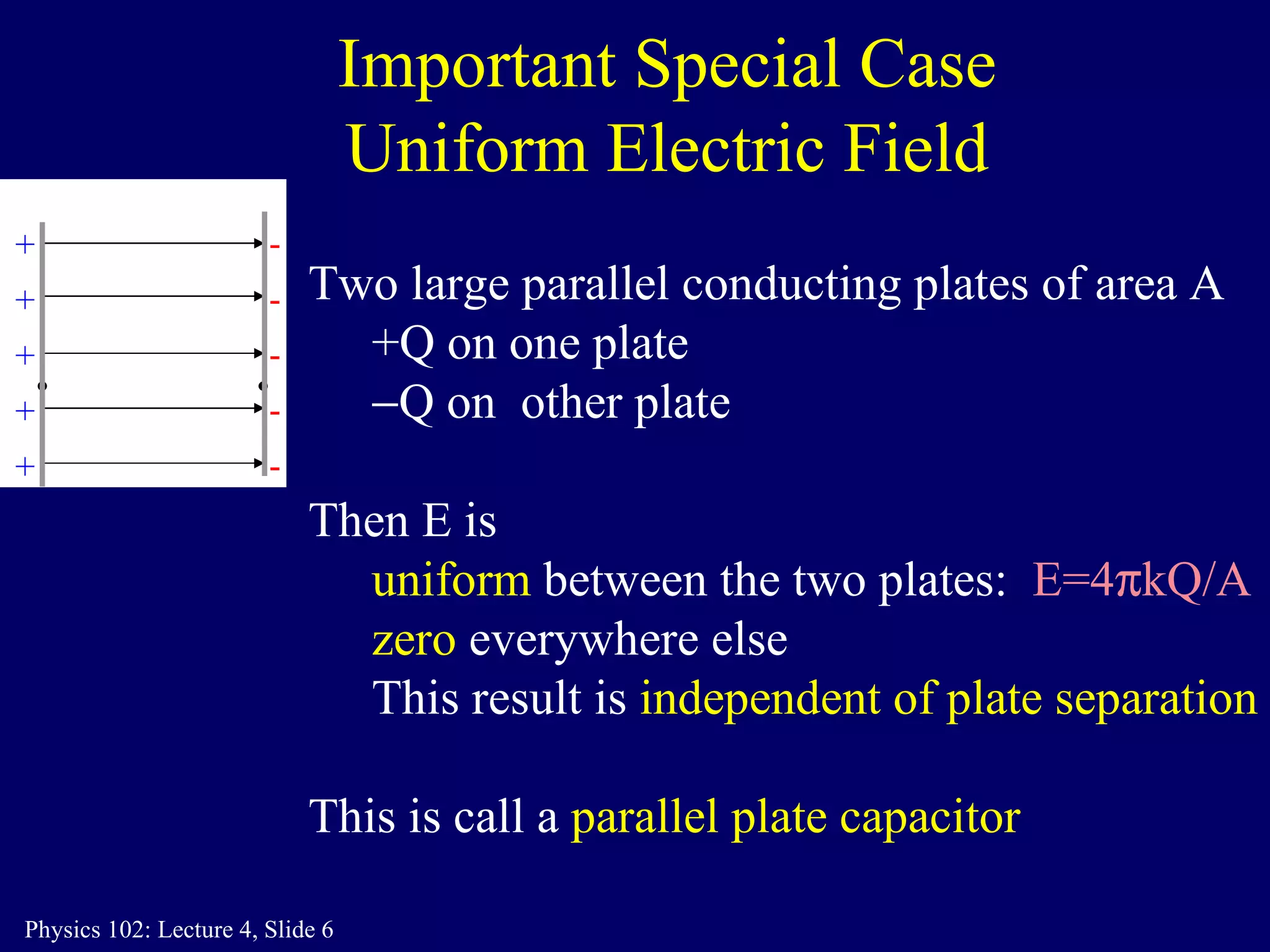
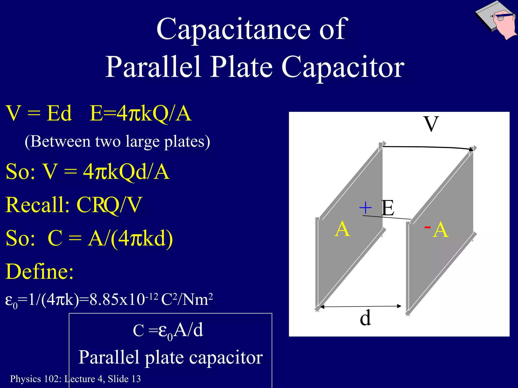
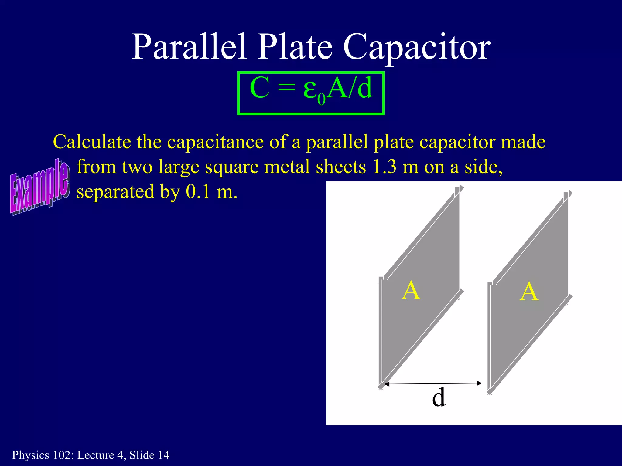
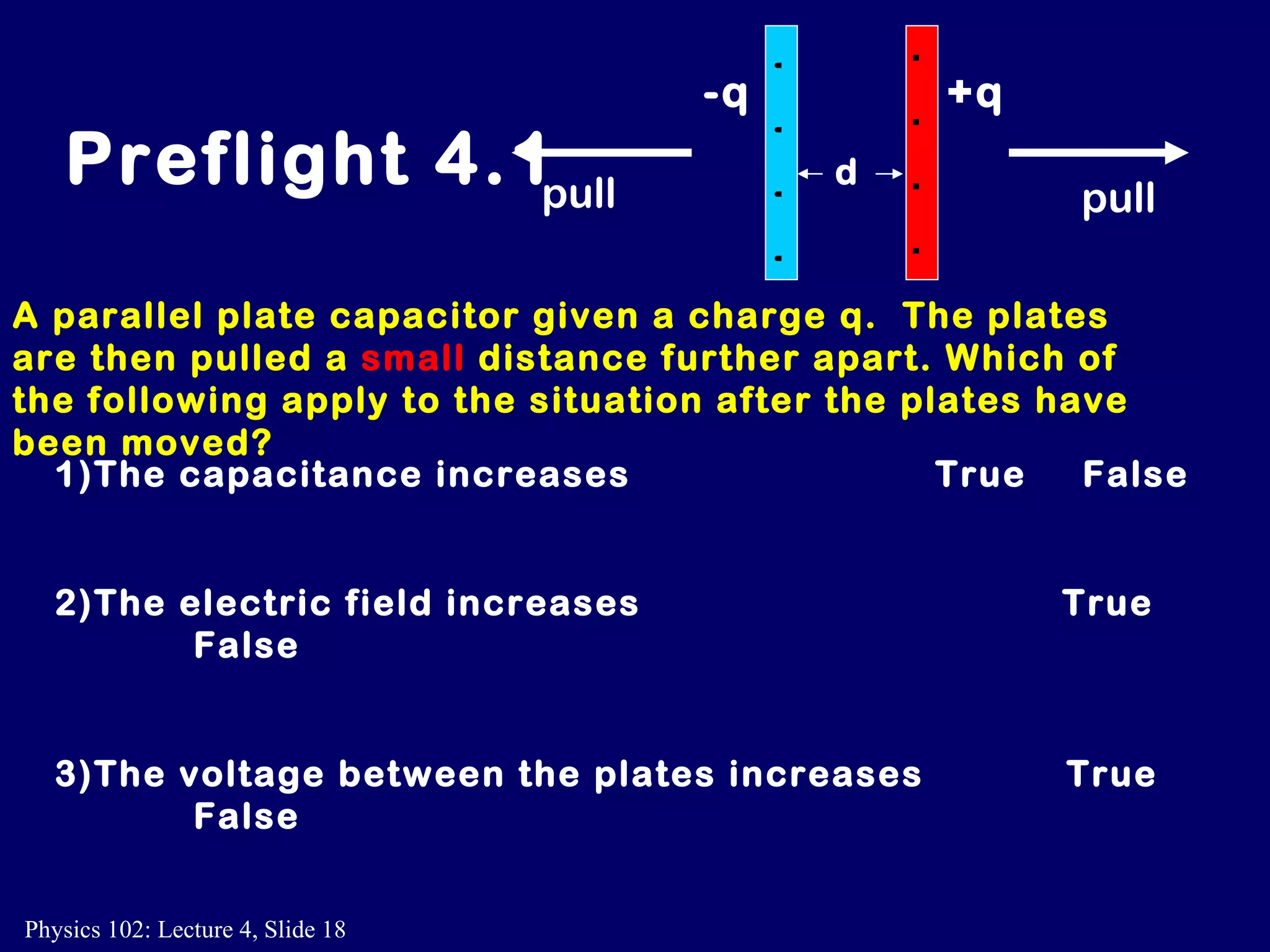
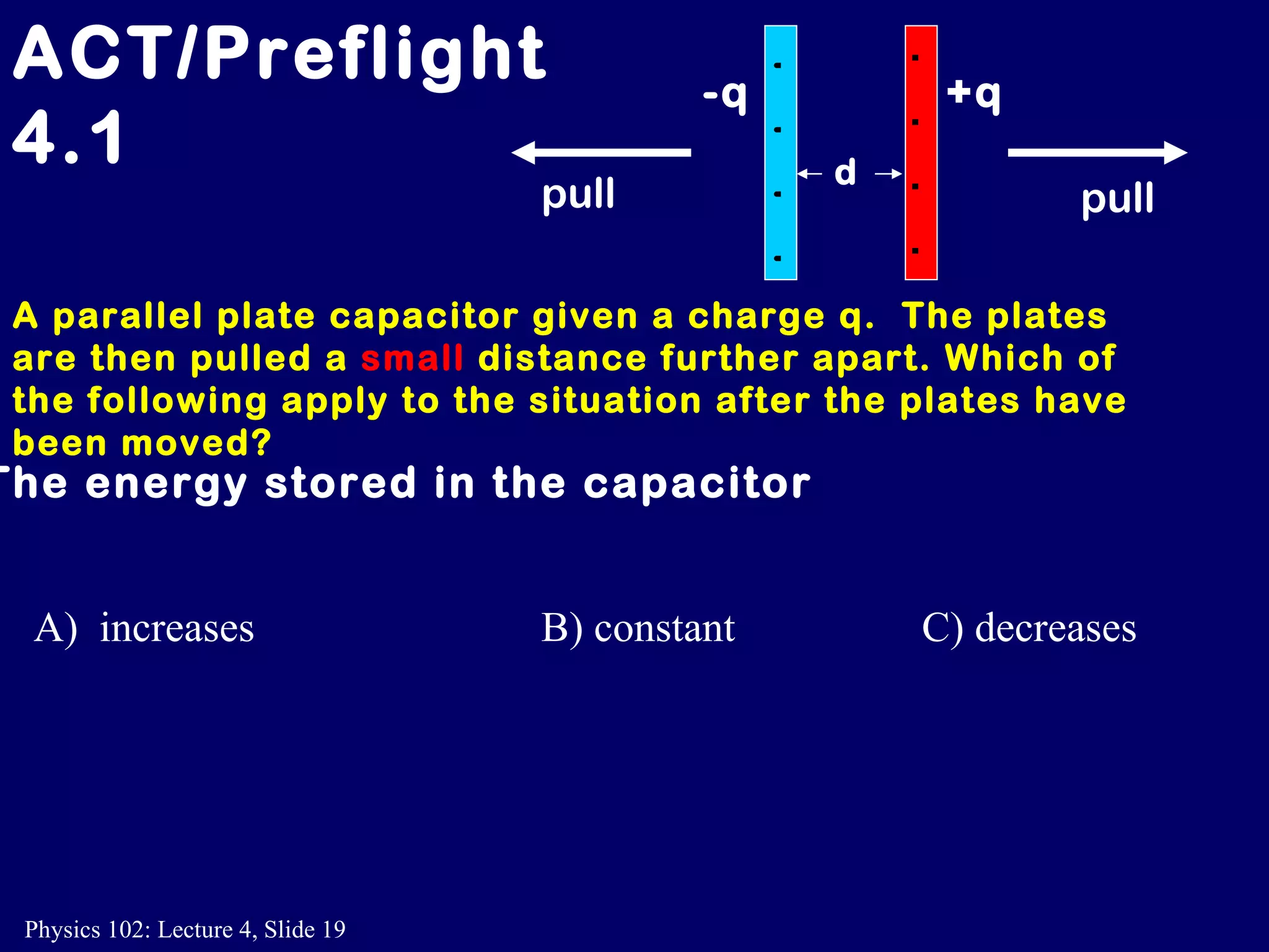
2. For a parallel plate capacitor, the capacitance is given by C = ε0A/d, where ε0 is the permittivity of free space, A is the plate area, and d is the plate separation.
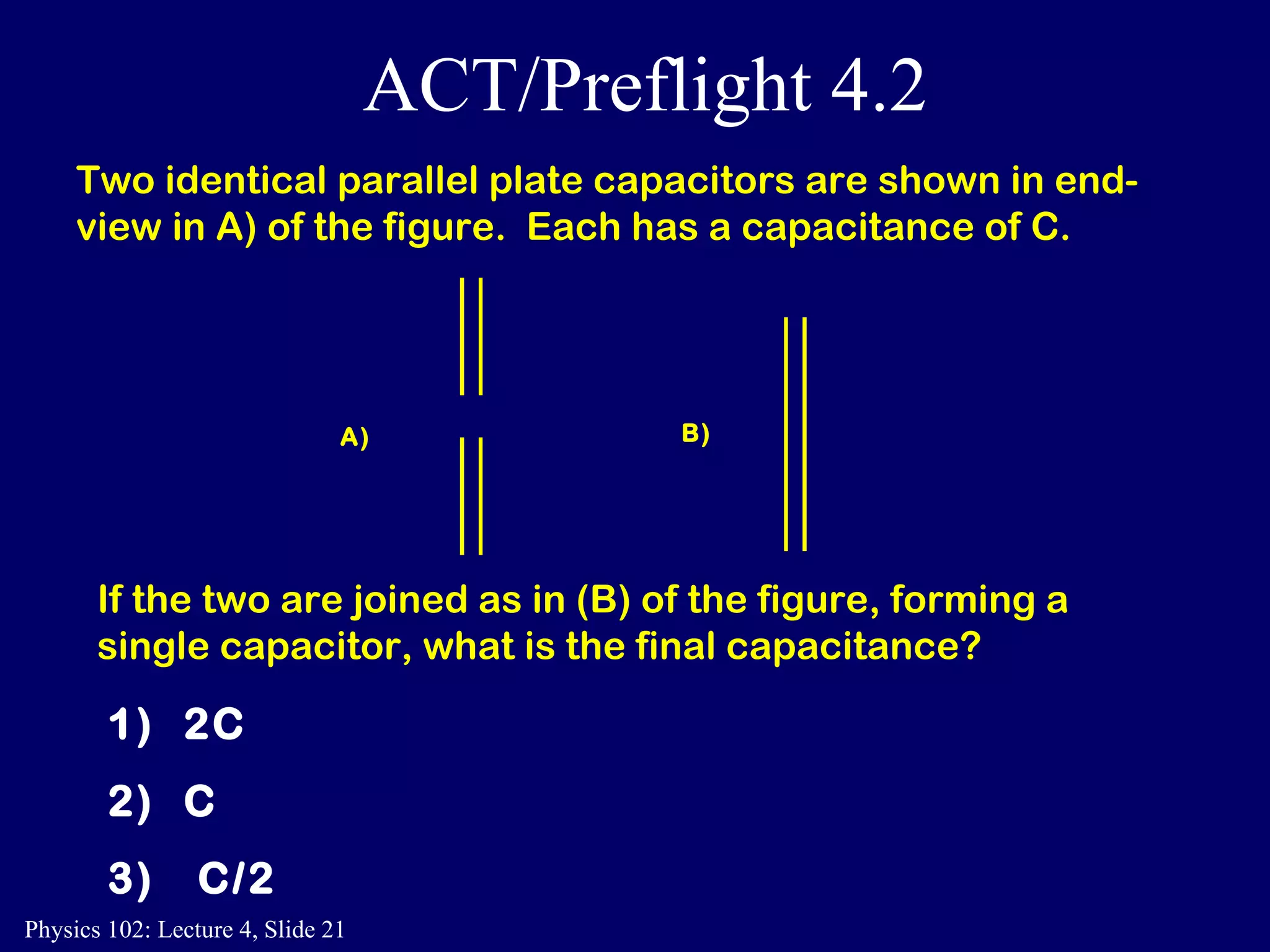
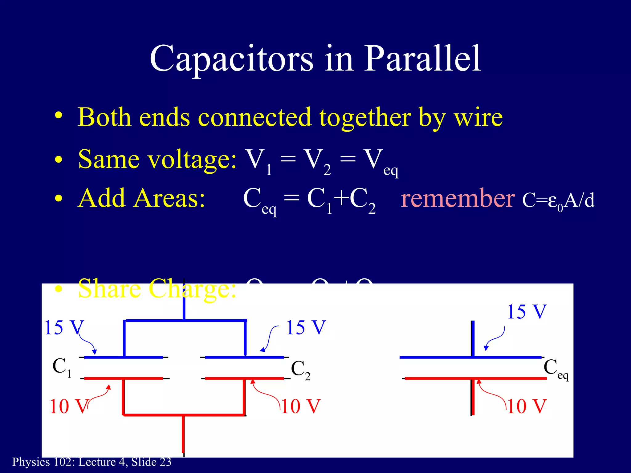
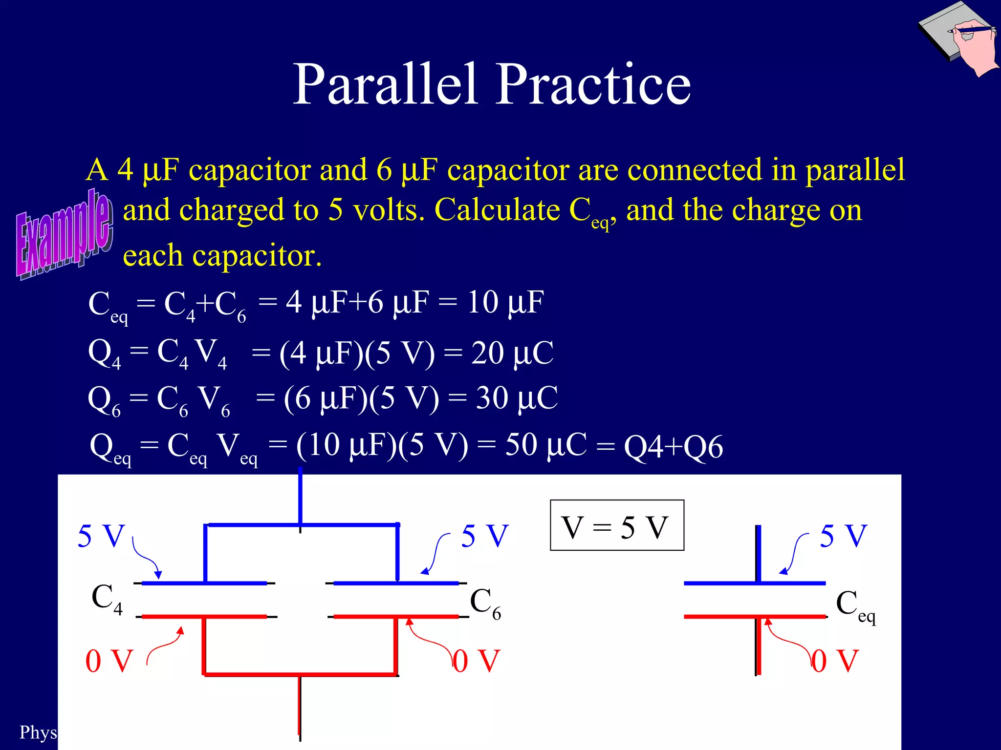
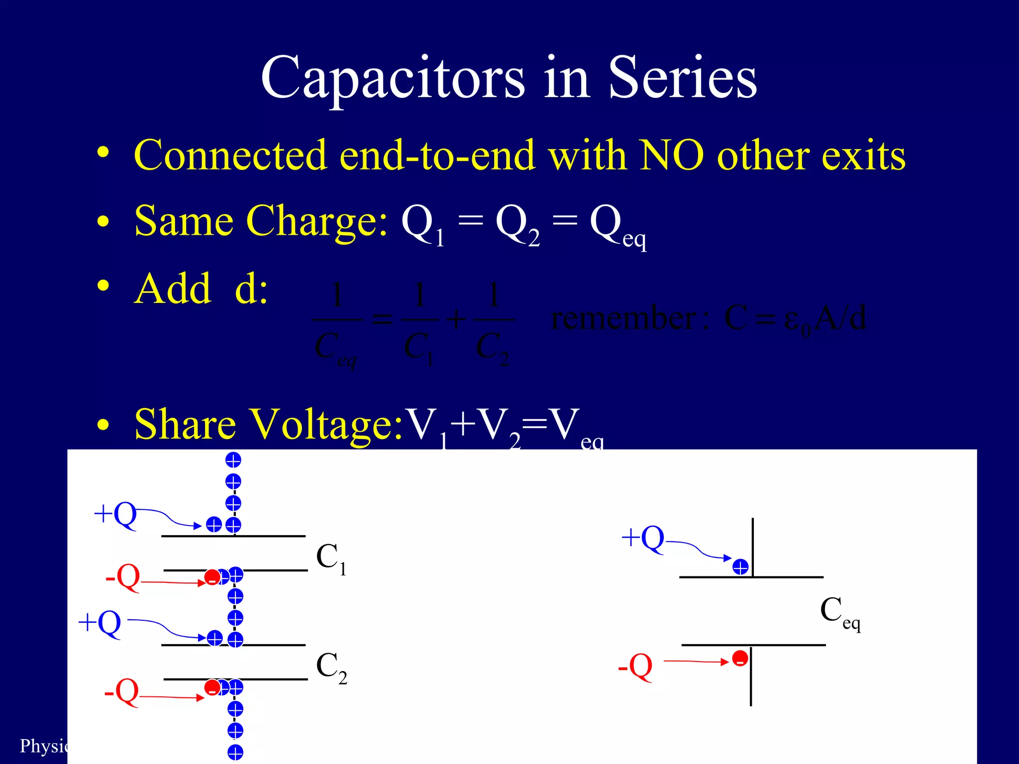
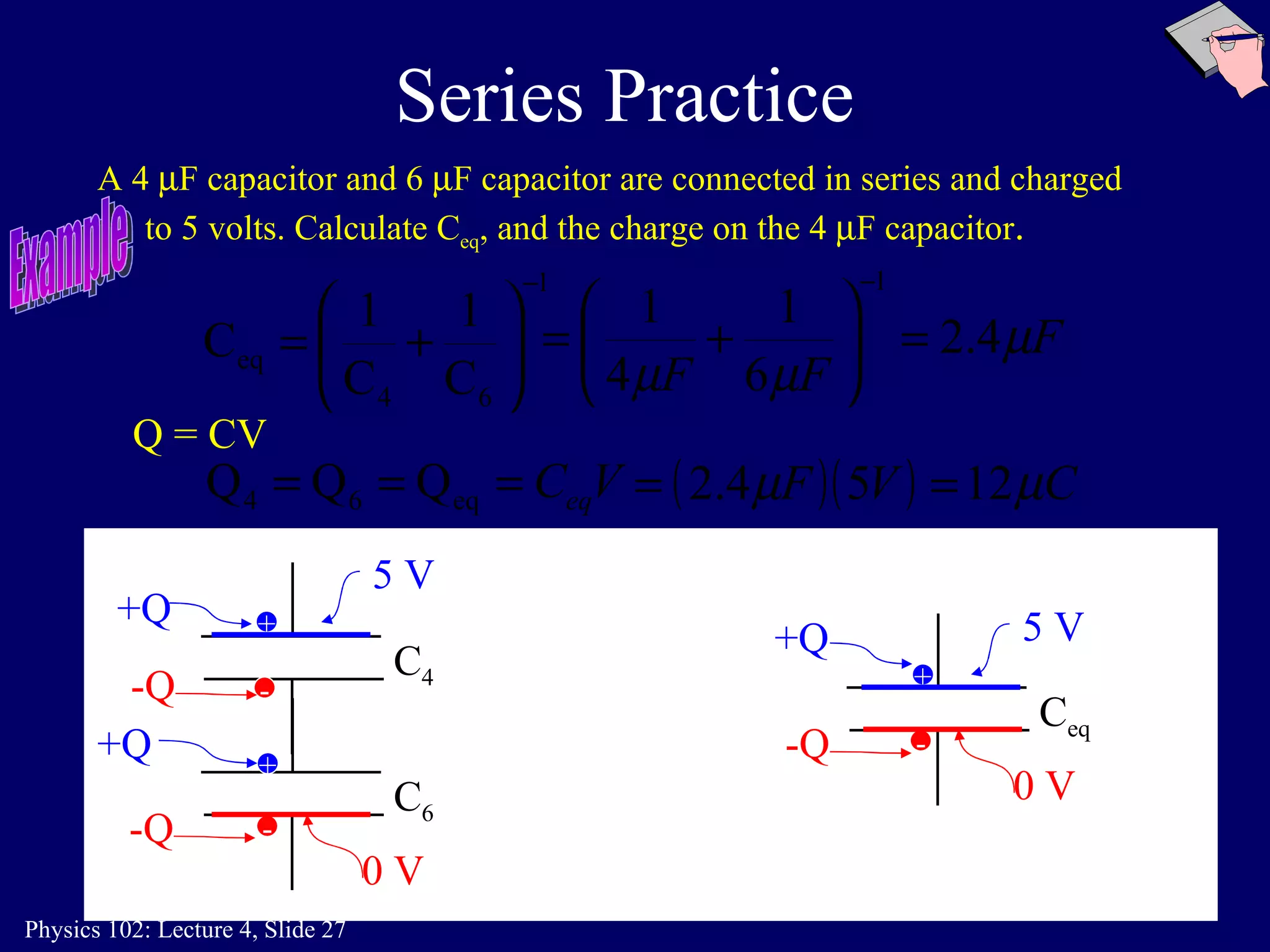
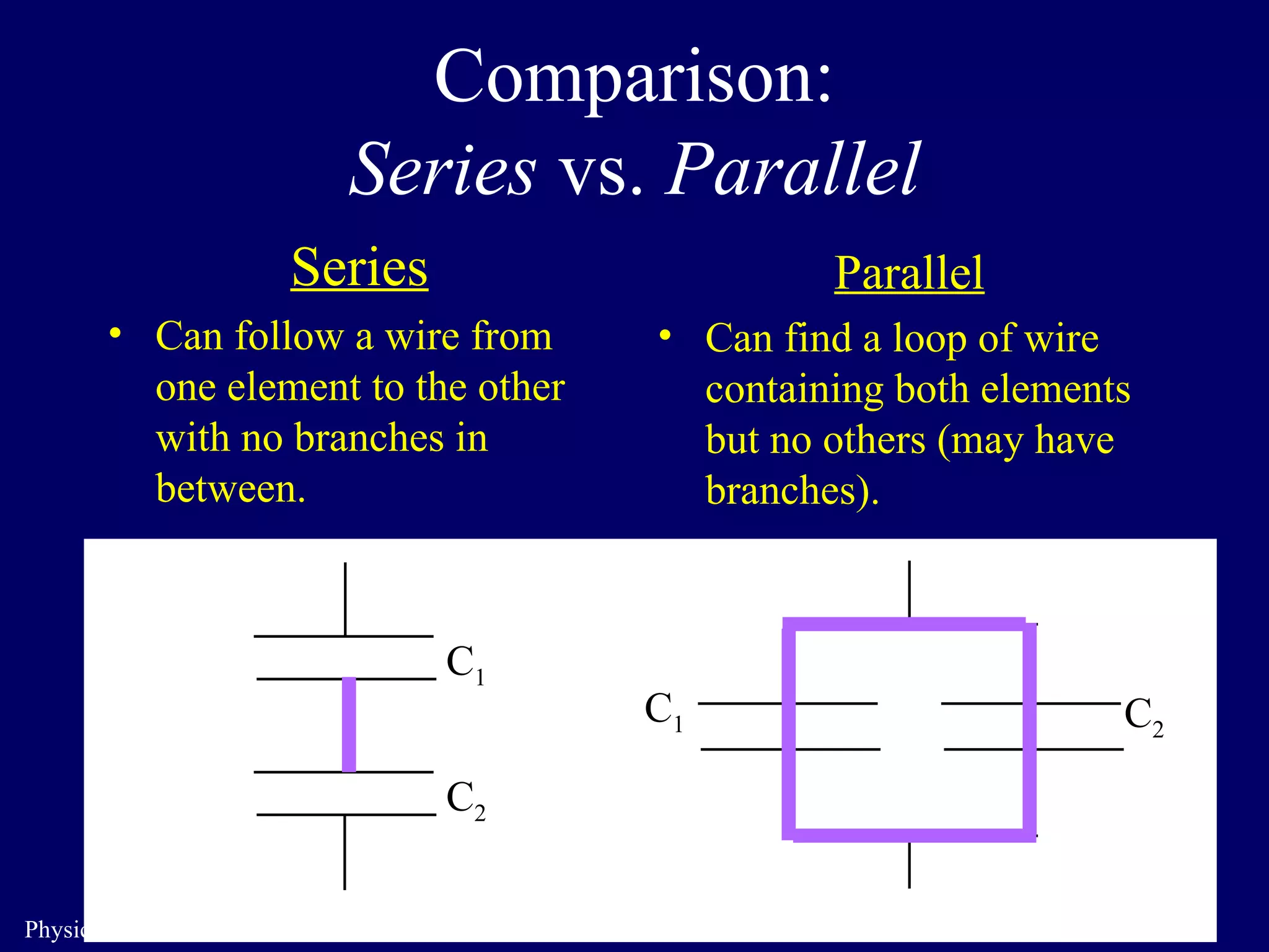
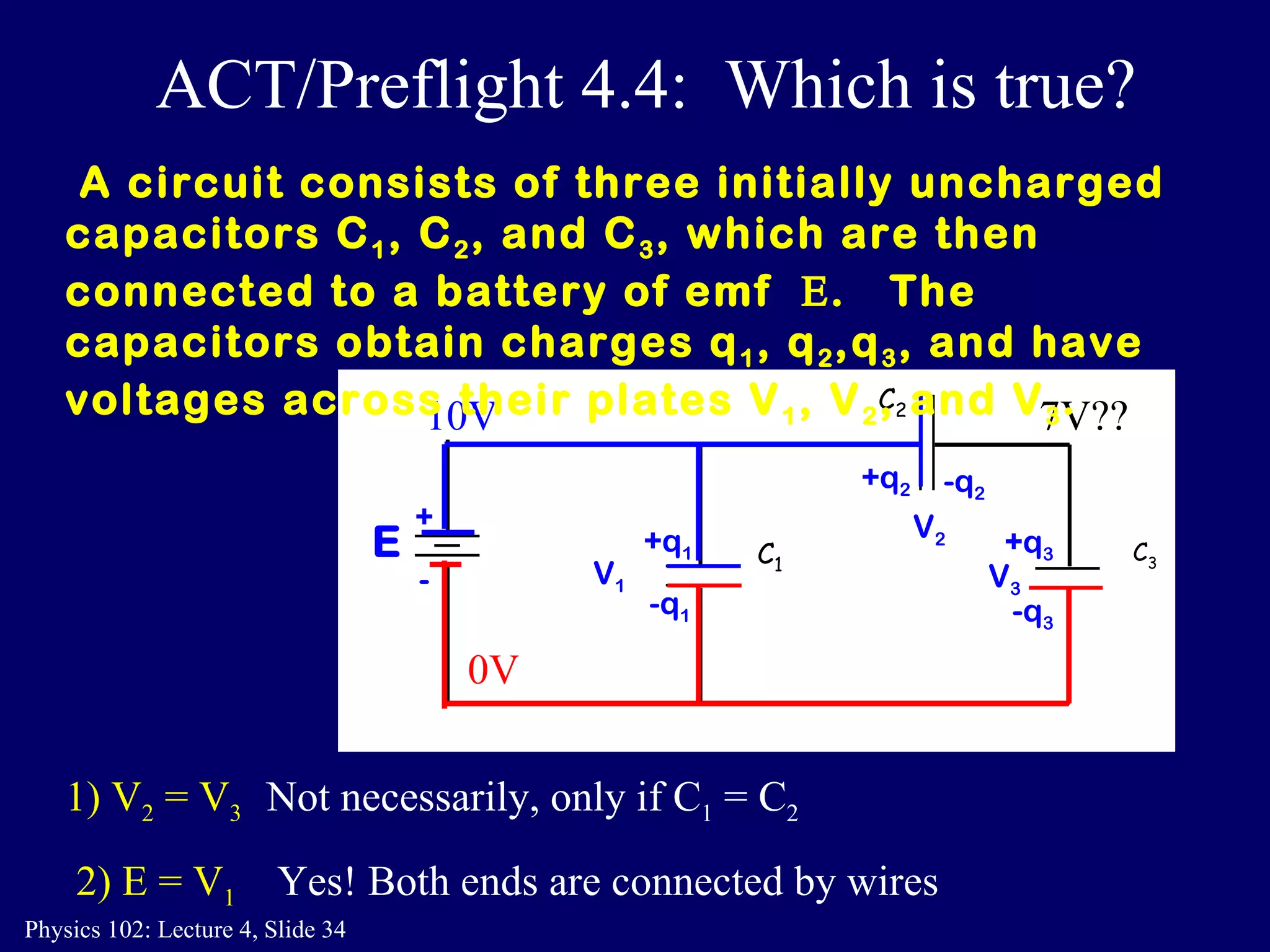
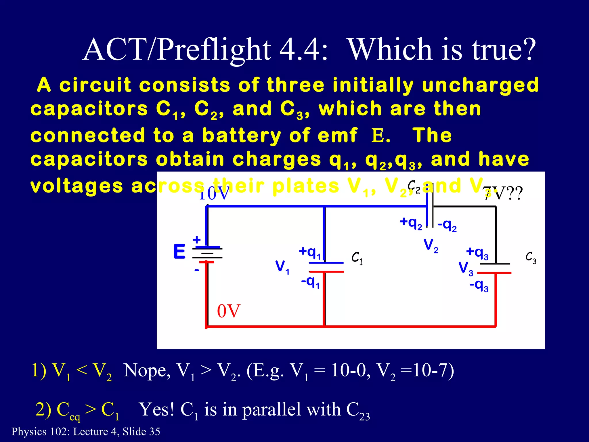
3. Capacitors can be connected in parallel or in series. For capacitors in parallel, the total capacitance is the sum of the individual capacitances. For capacitors in series, the total capacitance is given by 1/(1/C1 + 1/C2).


![Coded Agents – with UiPath SDK + LangGraph [Virtual Hands-on Workshop]](https://cdn.slidesharecdn.com/ss_thumbnails/codedagentsdeck-251215155422-5497c599-thumbnail.jpg?width=640&height=640&fit=bounds)


