Download as PDF, PPTX


![System
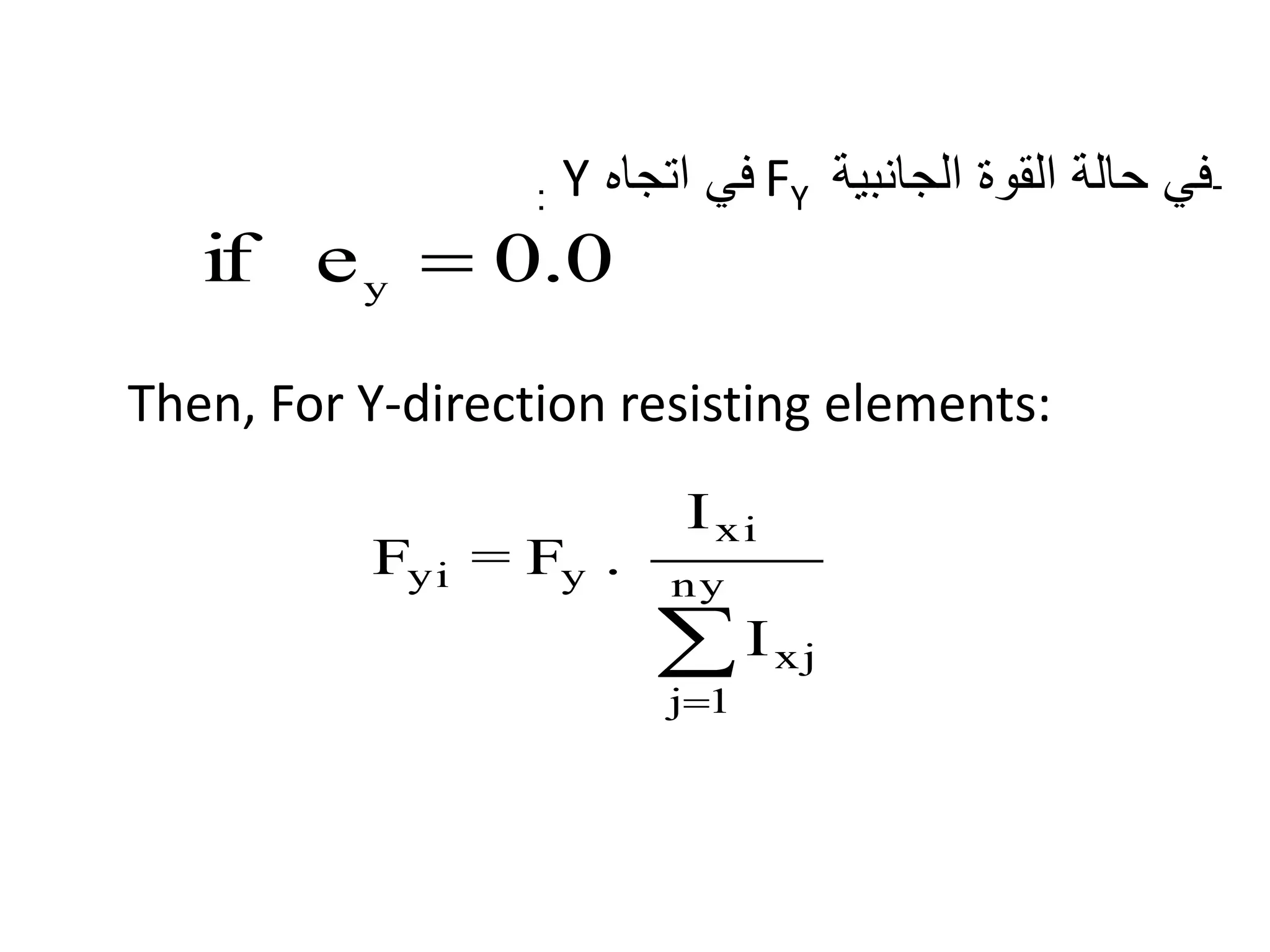
in
Section Iy Yi
Iy . Yi
2 Iy . Yi Fx' Fx"
Fx/
column
Fx/
frameX-
directio
n
(m x m) (m4) (m)
Frame
(1-1)
0.8x0.60 0.0179 -1.94 0.0674 -0.0347 0.0764 -0.027 0.050
0.231.0x0.80 0.0467 -1.94 0.1758 -0.0906 0.1994 -0.070 0.130
0.8x0.60 0.0179 -1.94 0.0674 -0.0347 0.0764 -0.027 0.050
Frame
(2-2)
1.0x0.80 0.0467 1.06 0.0525 0.0495 0.1994 0.038 0.237
0.771.0x1.00 0.0583 1.06 0.0655 0.0618 0.2489 0.047 0.296
1.0x0.80 0.0467 1.06 0.0525 0.0495 0.1994 0.038 0.237
SUM 0.2342 0.4809 1.0000 0.00 1.00 1.00
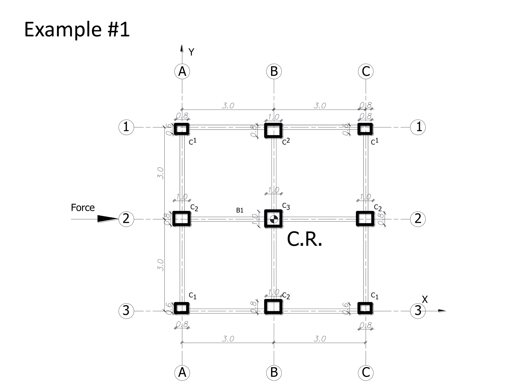
3 – find the values of [Iy. Yi
2 ] in the X - direction](https://image.slidesharecdn.com/lateralloadresistingsystems-150301162301-conversion-gate01/75/Lateral-load-resisting-systems-40-2048.jpg)
![System in Section Ix Xi
Ix. Xi
2 Ix. Xi Fy' Fy"
Fy/
column
Fy/
Frame
Y-direction (m x m) (m4) (m)
Frame
(A-A)
0.8x0.60 0.01008 -3 0.0907 -0.0302 0.0000 0.023 0.023
0.121.0x0.8 0.02987 -3 0.2688 -0.0896 0.0000 0.069 0.069
0.8x0.6 0.01008 -3 0.0907 -0.0302 0.0000 0.023 0.023
Frame
(C-C)
0.8x0.6 0.01008 3 0.0907 0.0302 0.0000 -0.023 -0.023
-0.121.0x0.8 0.02987 3 0.2688 0.0896 0.0000 -0.069 -0.069
0.8x0.6 0.01008 3 0.0907 0.0302 0.0000 -0.023 -0.023
SUM 0.1001 0.9005 0.0000 0.0000 0.0000 0.0000 0.0000
4– Calculate the values of [Ix. Xi
2 ] in the Y - direction](https://image.slidesharecdn.com/lateralloadresistingsystems-150301162301-conversion-gate01/75/Lateral-load-resisting-systems-41-2048.jpg)

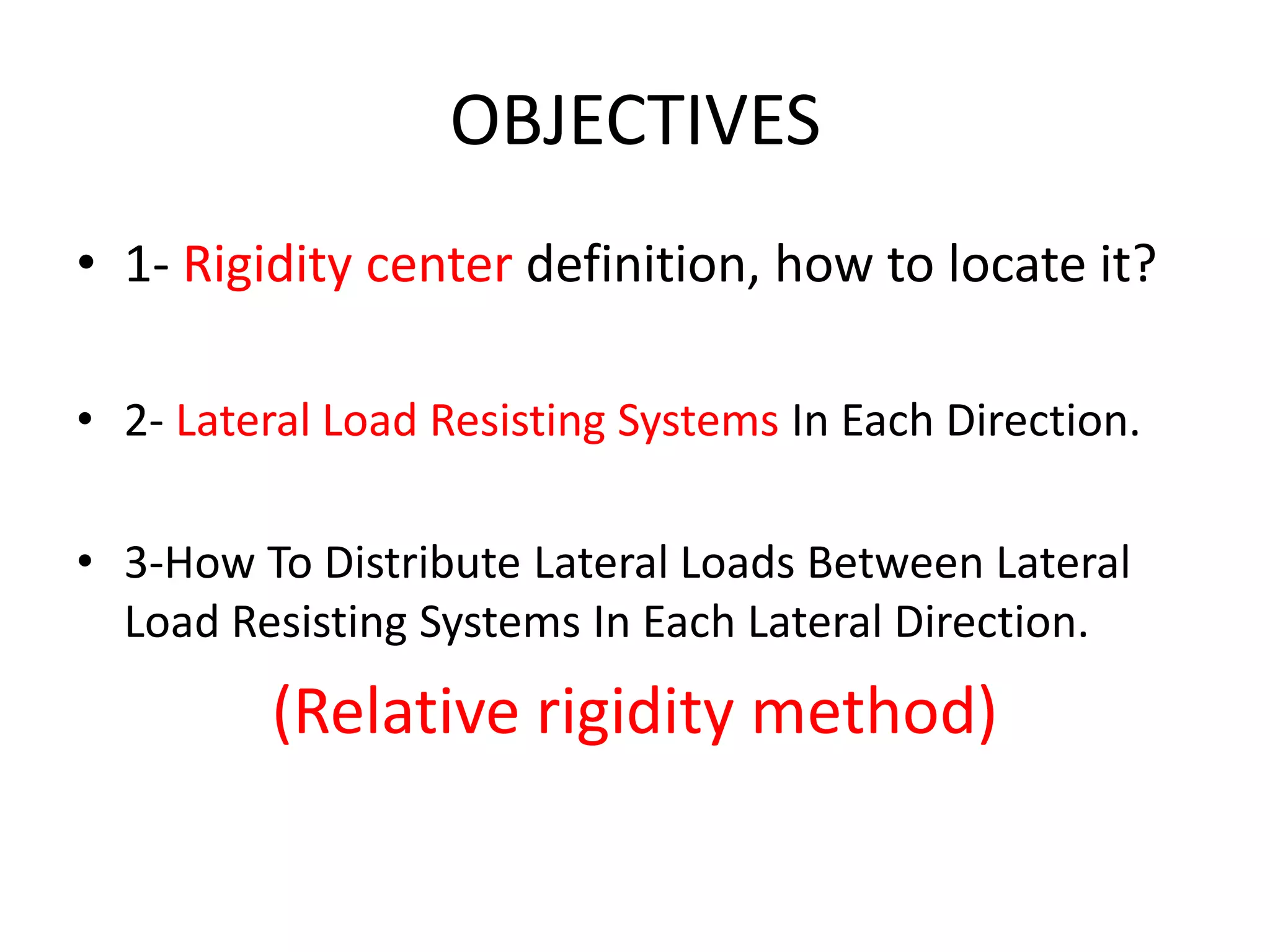
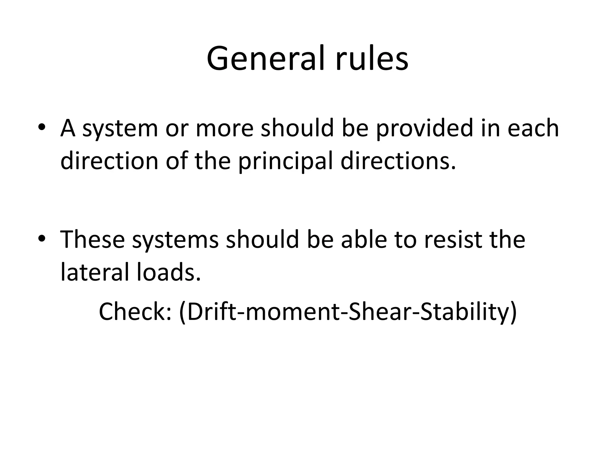
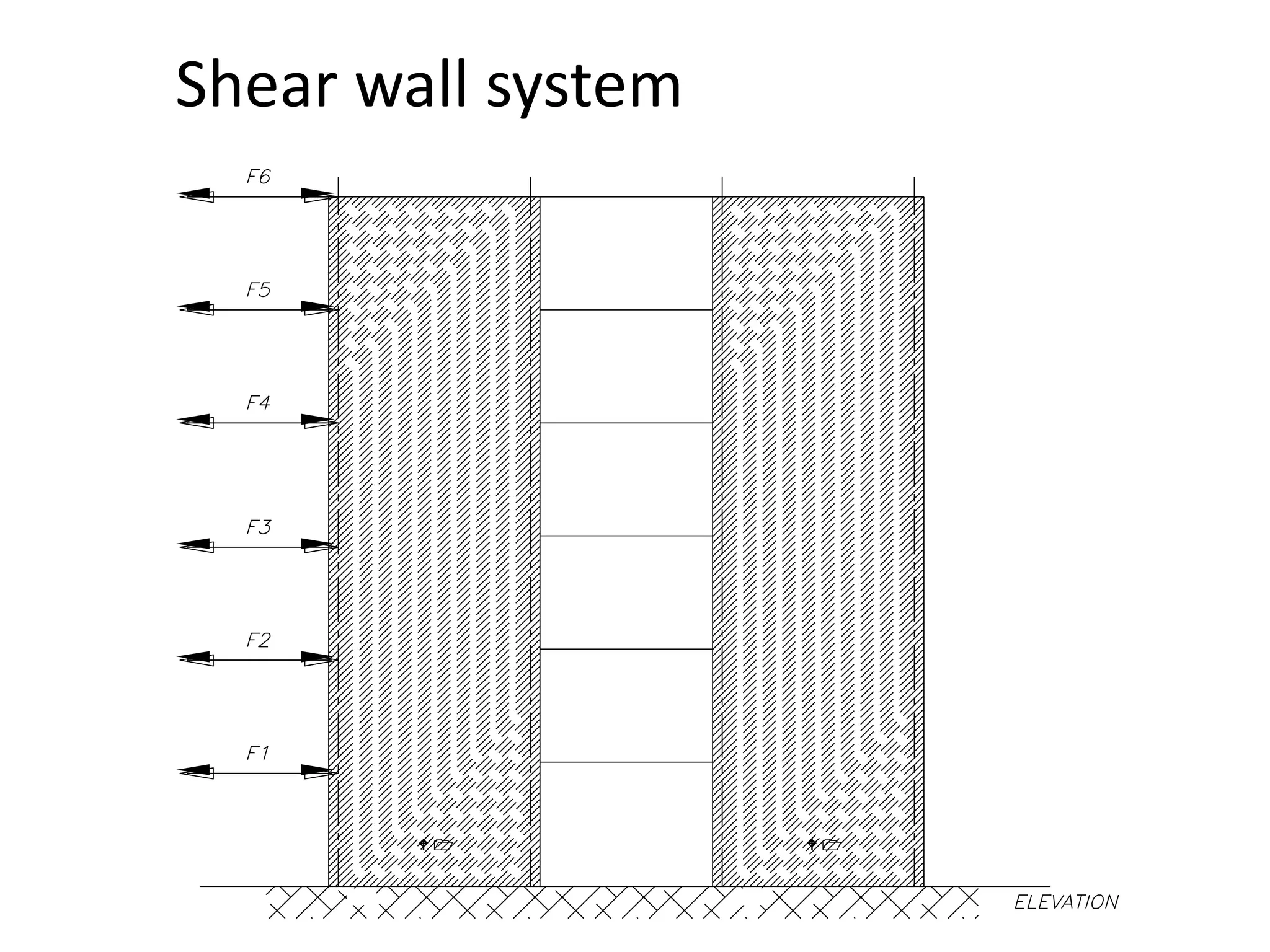
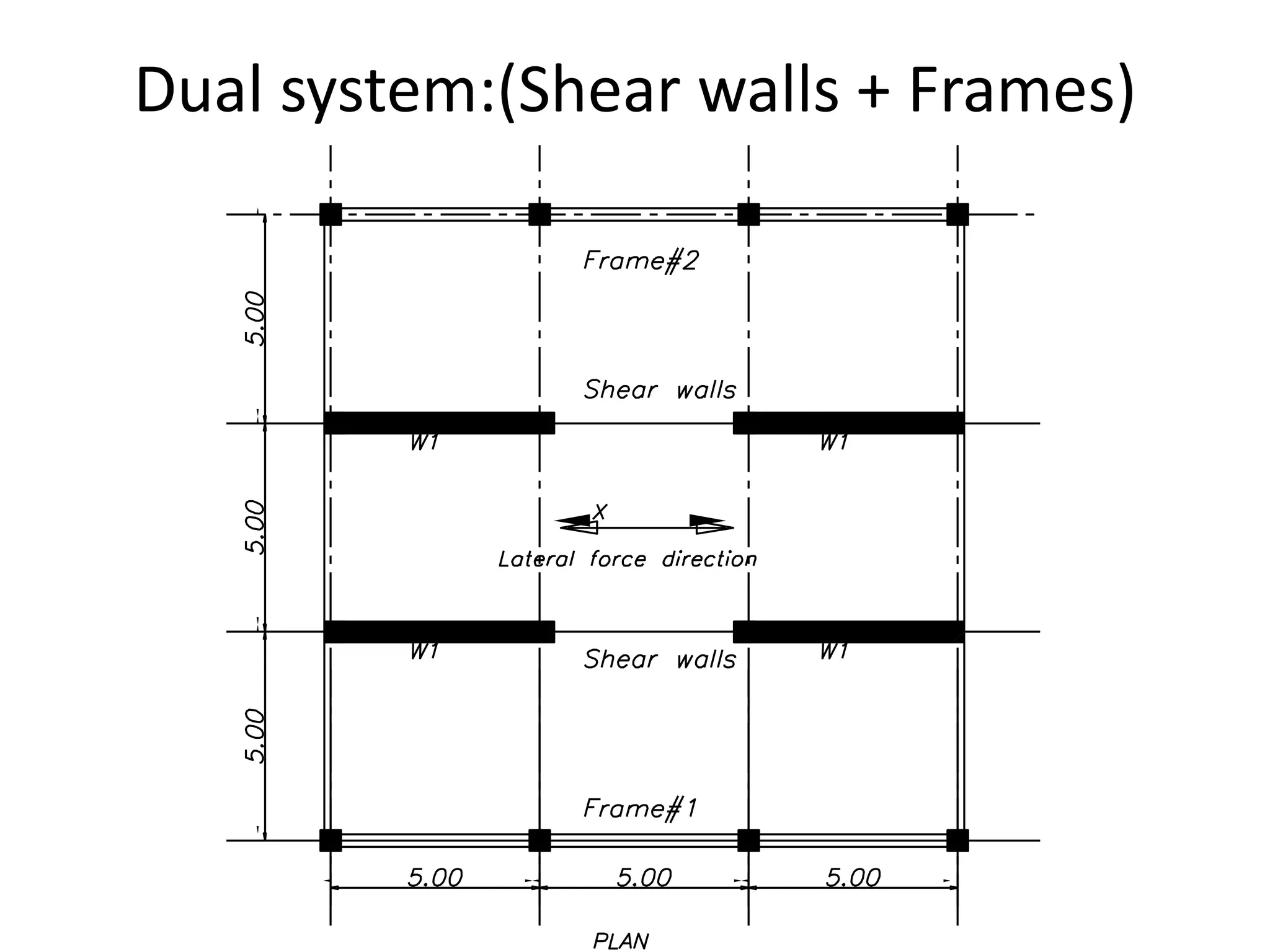
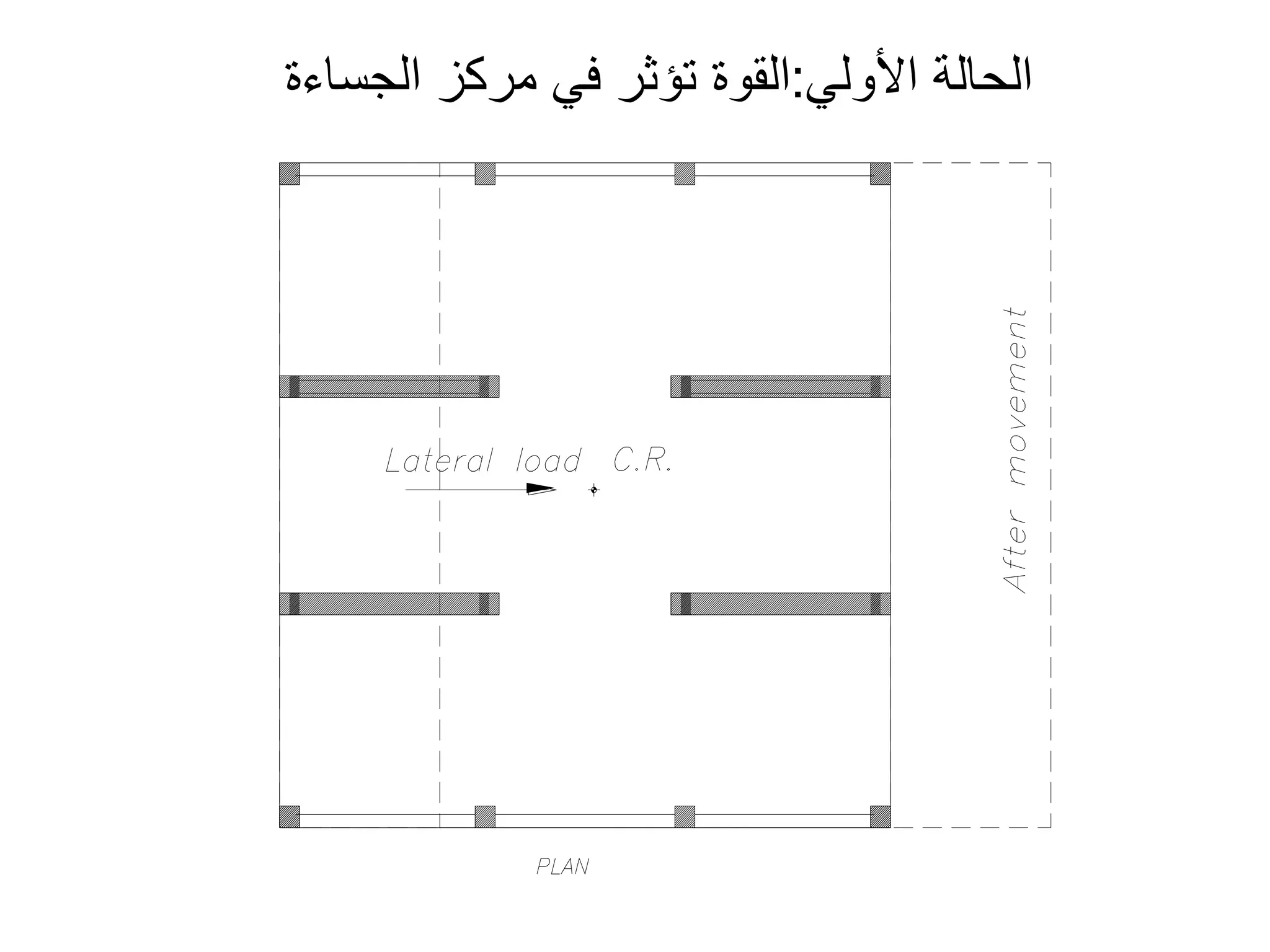
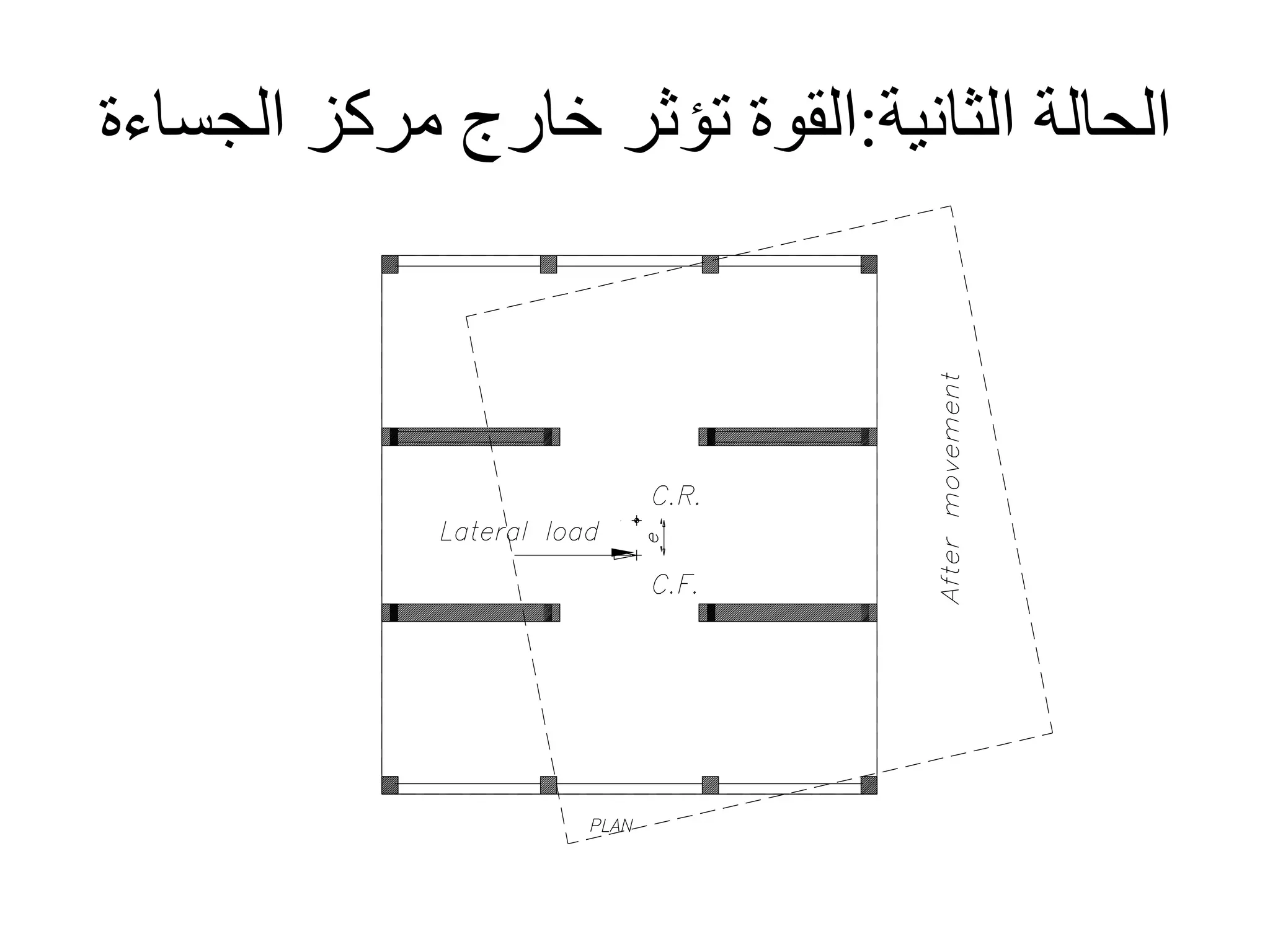
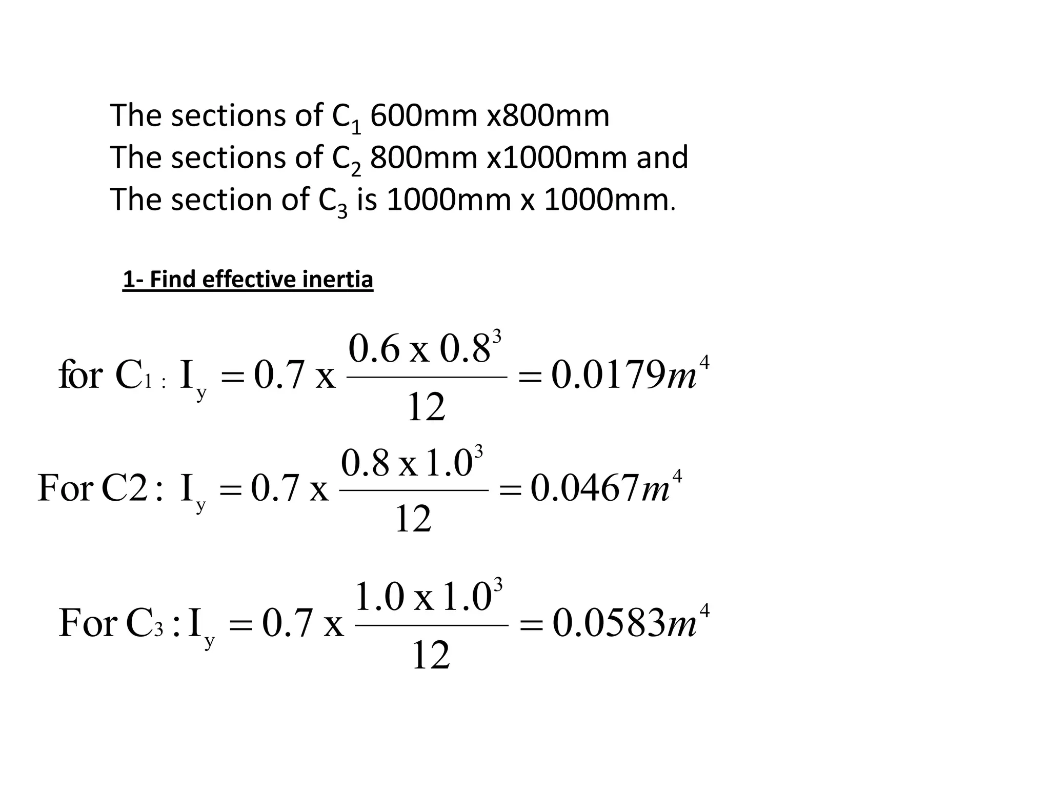
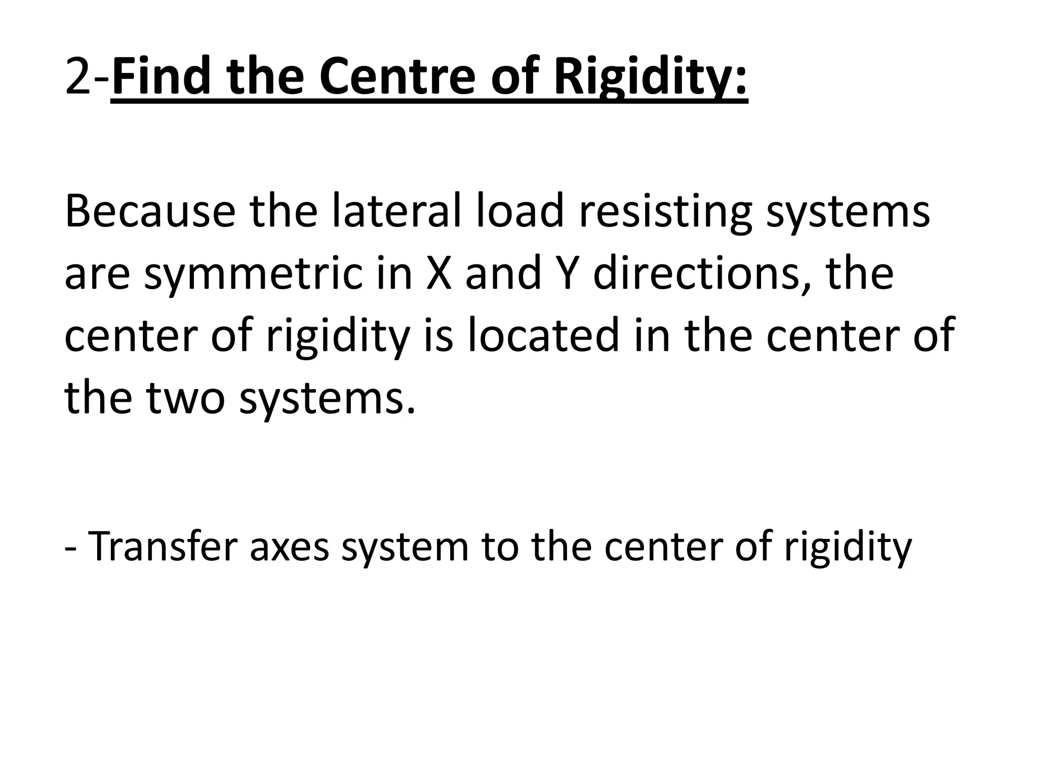
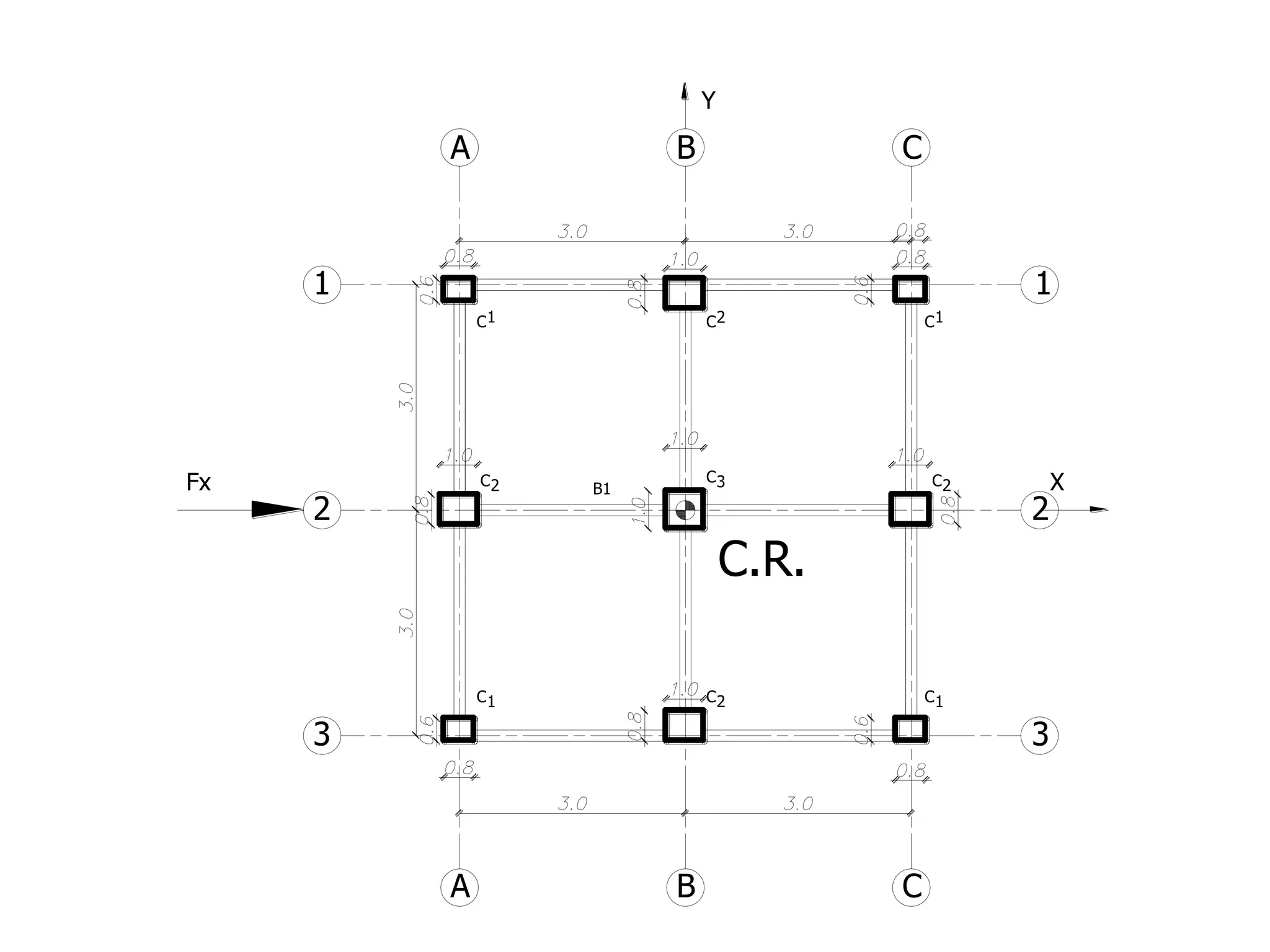
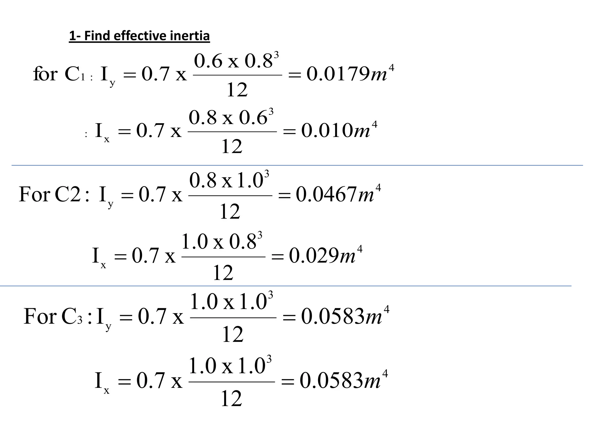
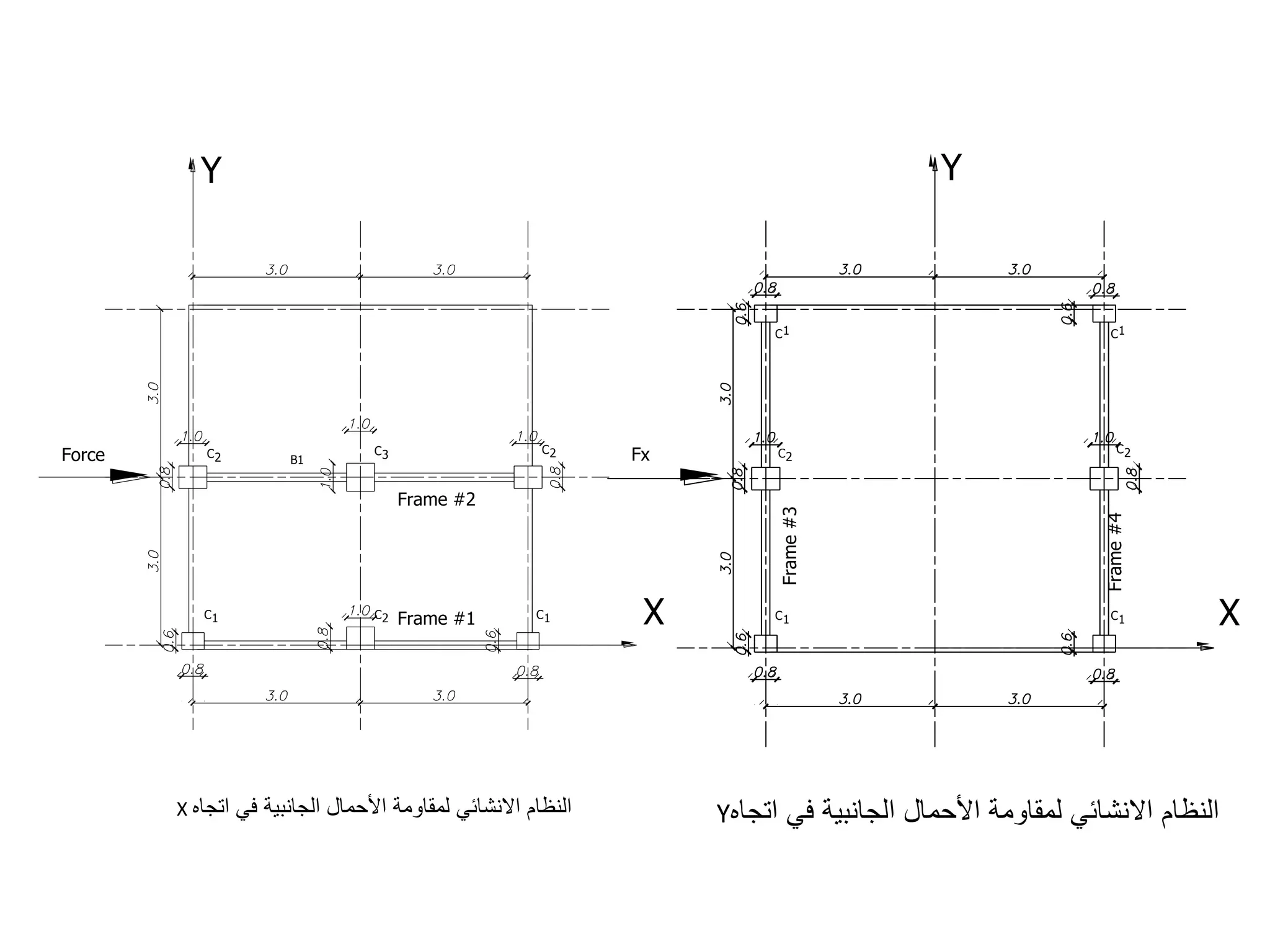
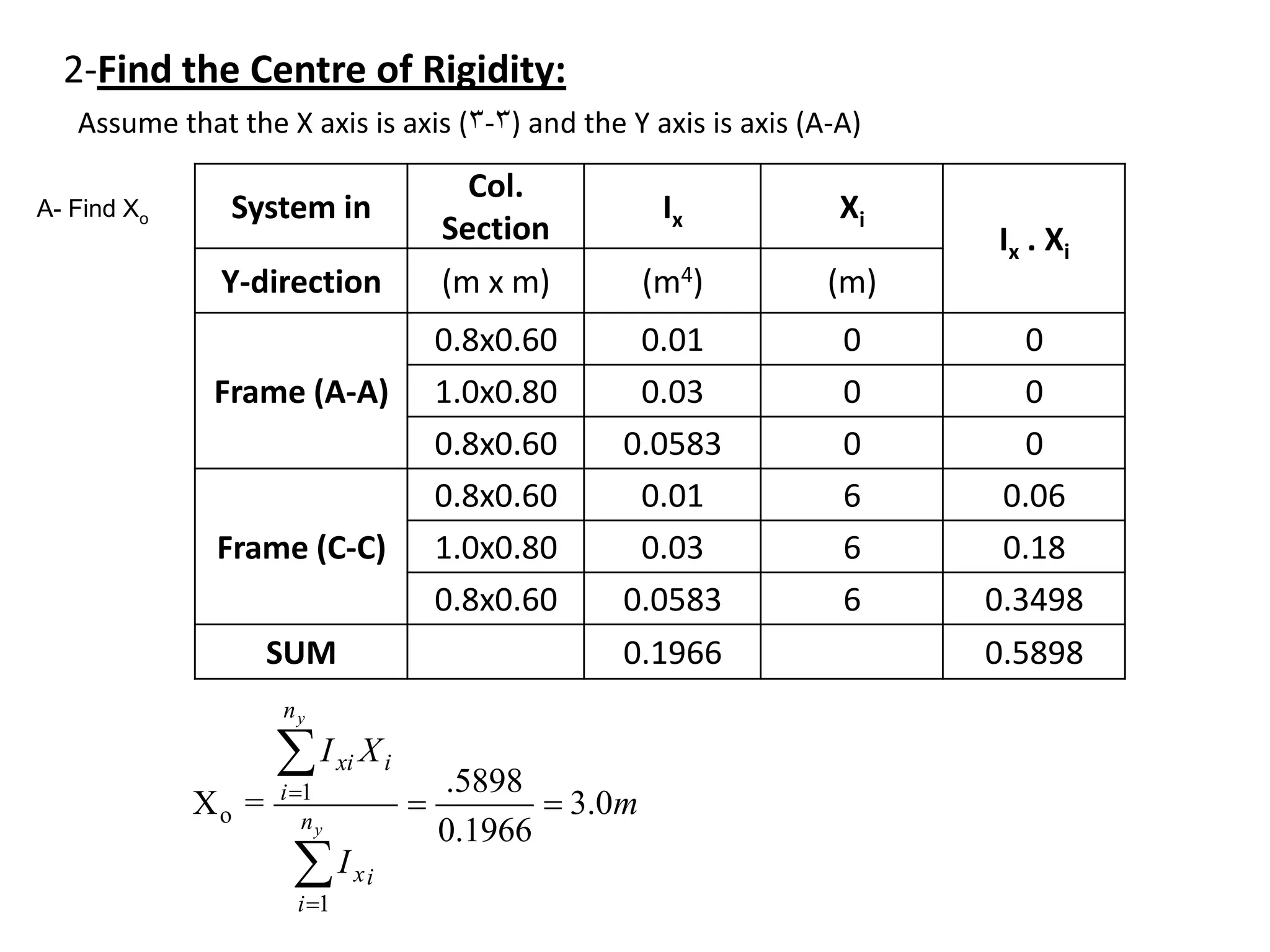
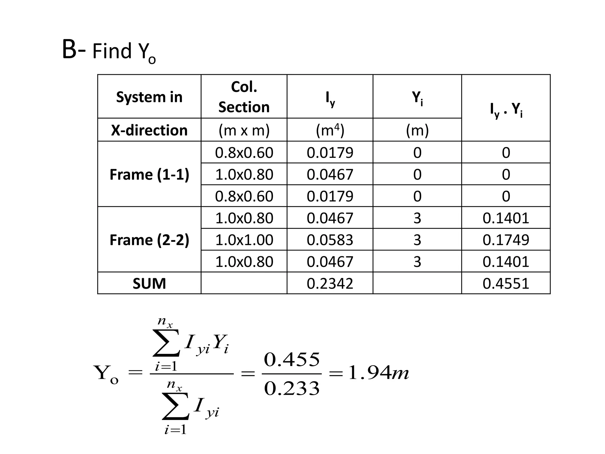
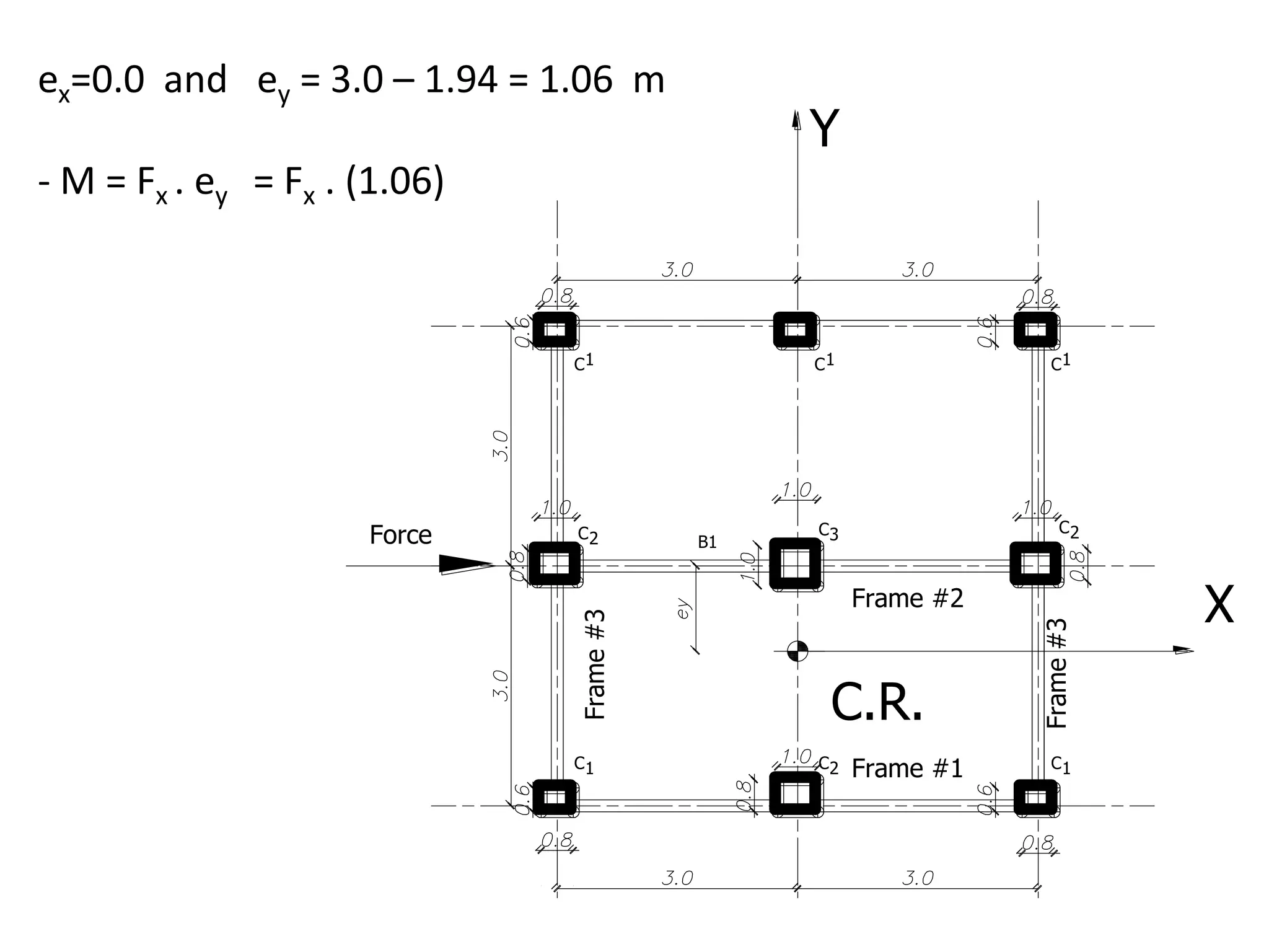
The document discusses lateral load resisting systems in high-rise concrete buildings, detailing types such as moment-resisting frames and shear walls, as well as their combinations. It covers key concepts including the definition of the center of rigidity, methods for distributing lateral loads, and the evaluation of structural stability through critical parameters. Practical examples illustrate calculations for effective inertia and load distribution among various structural frames.