Design and Check stability of Gravity Retaining wall
•
1 like•461 views

This document contains section notes on foundation engineering from a third year civil engineering course. It discusses terminology and sizing parameters for retaining walls, including factors related to height. It also describes two potential failure modes - overturning and sliding - and provides equations for calculating resisting and driving moments or forces to ensure adequate safety factors against each failure mode. Friction coefficients are provided for different soil types. The use of passive pressure is also mentioned to supplement friction forces if insufficient on their own.

More Related Content
What's hot
What's hot (20)
Recently uploaded
Recently uploaded (20)
Design and Check stability of Gravity Retaining wall
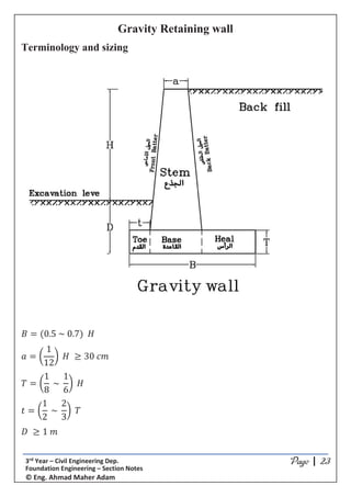
- 1. *5;9*5;9*5;9*5;9 ͮ ϯƌĚ zĞĂƌ ʹ ŝǀŝů ŶŐŝŶĞĞƌŝŶŐ ĞƉ͘ ŽƵŶĚĂƚŝŽŶ ŶŐŝŶĞĞƌŝŶŐ ʹ ^ĞĐƚŝŽŶ EŽƚĞƐ Ξ ŶŐ͘ ŚŵĂĚ DĂŚĞƌ ĚĂŵ Gravity Retaining wall Terminology and sizing ܤ ൌ ሺͲǤͷ ̱ ͲǤሻ ܪ ܽ ൌ ൬ ͳ ͳʹ ൰ ܪ ͵Ͳ ܿ݉ ܶ ൌ ൬ ͳ ͺ ̱ ͳ ൰ ܪ ݐ ൌ ൬ ͳ ʹ ̱ ʹ ͵ ൰ ܶ ܦ ͳ ݉
- 2. *5;9*5;9*5;9*5;9 ͮ ϯƌĚ zĞĂƌ ʹ ŝǀŝů ŶŐŝŶĞĞƌŝŶŐ ĞƉ͘ ŽƵŶĚĂƚŝŽŶ ŶŐŝŶĞĞƌŝŶŐ ʹ ^ĞĐƚŝŽŶ EŽƚĞƐ Ξ ŶŐ͘ ŚŵĂĚ DĂŚĞƌ ĚĂŵ Failure modes 1- Overturning اﻟﺠﺬع دوران ﻳﺴﺒﺐ اﻟﱰﺑﺔ ﰲ اﳌﺘﻮﻟﺪ اﻟﺠﺎﻧﺒﻲ اﻟﻀﻐﻂStemﻧﻘﻄﺔ ﺣﻮلBﺣﻮل ﻛﻠﻪ اﻟﺤﺎﺋﻂ ودوران ، ﻧﻘﻄﺔA.اﻟﺤﺎﺋﻂ ﻓﻮق اﻟﱰﺑﺔ ووزن ﻧﻔﺴﻪ اﻟﺤﺎﺋﻂ وزن اﻟﺪوران ﻫﺬا وﻳﻘﺎوم . Overturning moment ܯ௩ ௧௨ = moment due to lateral earth forces. Resisting moment ܯோ௦௦௧ = moment due to weight of soil and weight of wall. ﻫﻨﺎ ﻳﻜﻮن ان وﻻﺑﺪاﳌﻘﺎوﻣﺔ واﻟﻌﺰوم اﳌﺆﺛﺮة اﻟﻌﺰوم ﺑني ﻣﻨﺎﺳﺐ اﻣﺎن ﻣﻌﺎﻣﻞ ك ࡲǤ ࡻǤ ࡿࢇࢍࢇ࢙࢚ ࢜ࢋ࢚࢛࢘࢘ࢍ = ࡹࡾࢋ࢙࢙࢚ࢍ ࡹ࢜ࢋ࢘ ࢚࢛࢘ࢍ 1.5
- 3. *5;9*5;9*5;9*5;9 ͮ ϯƌĚ zĞĂƌ ʹ ŝǀŝů ŶŐŝŶĞĞƌŝŶŐ ĞƉ͘ ŽƵŶĚĂƚŝŽŶ ŶŐŝŶĞĞƌŝŶŐ ʹ ^ĞĐƚŝŽŶ EŽƚĞƐ Ξ ŶŐ͘ ŚŵĂĚ DĂŚĞƌ ĚĂŵ 2- Sliding اﻟ ﺗﺤﺮك ﻳﺴﺒﺐ اﻟﱰﺑﺔ ﰲ اﳌﺘﻮﻟﺪ اﻟﺠﺎﻧﺒﻲ اﻟﻀﻐﻂﺠﺬعStemﺣﺮﻛﺔ()اﻧﺰﻻق ﺟﺎﻧﺒﻴﺔاﻟﻘﻄﺎع ﻋﲆBB’ ﻋﲆ ()اﻧﺰﻻق ﺟﺎﻧﺒﻴﺔ ﺣﺮﻛﺔ ﻛﻠﻪ اﻟﺤﺎﺋﻂ ﺗﺤﺮك وﻳﺴﺒﺐاﻟﻘﻄﺎعAA’. ﻗﻮ اﻻﻧﺰﻻق ﻫﺬا وﻳﻘﺎومىﻋﲆ واﻟﻘﺎﻋﺪة اﻟﺠﺬع ﺑني اﻻﺣﺘﻜﺎكاﻟﻘﻄﺎعBB’وﻗﻮ ،ىاﻟﻘﺎﻋﺪة ﺑني اﻻﺣﺘﻜﺎك اﻟﻘﻄﺎع ﻋﲇ ﻣﻨﻬﺎ اﺳﻔﻞ واﻟﱰﺑﺔAA’. Sliding forces ܨௌௗ = Active Lateral earth forces Resisting forces ܨோ௦௦௧ = Friction forces اﻟﺮأﺳﻴﺔ اﻟﻘﻮي ﻣﺠﻤﻮع ﺗﺴﺎوي اﻻﺣﺘﻜﺎك ﻗﻮي و)(ﻓﻮﻗﻪ اﻟﱰﺑﺔ ووزن اﻟﺤﺎﺋﻂ وزنﻣﻌﺎﻣﻞ ﰲ ﻣﴬوب اﻻﺣﺘﻜﺎكɊواﻟﺬياﻻﺣﺘﻜﺎك ﻓﻴﻪ ﻳﺤﺪث اﻟﺬي اﻟﻮﺳﻂ ﻧﻮع ﻋﲇ ﻳﺘﻮﻗﻒ. ܨோ௦௦௧= σ ݏݐ݄݃݅݁ݓ × ȝ in cohesionless soil ܨோ௦௦௧= σ ݏݐ݄݃݅݁ݓ × ȝ + (0.8×ܥ௨)×B in cohesive soil ȝ = 0.33 Clay ȝ = 0.6 Sand ȝ = 0.7 Friction between 2 concrete faces
- 4. *5;9*5;9*5;9*5;9 ͮ ϯƌĚ zĞĂƌ ʹ ŝǀŝů ŶŐŝŶĞĞƌŝŶŐ ĞƉ͘ ŽƵŶĚĂƚŝŽŶ ŶŐŝŶĞĞƌŝŶŐ ʹ ^ĞĐƚŝŽŶ EŽƚĞƐ Ξ ŶŐ͘ ŚŵĂĚ DĂŚĞƌ ĚĂŵ ()اﻻﺣﺘﻜﺎك اﳌﻘﺎوﻣﺔ وﻗﻮي اﻻﻧﺰﻻق ﻗﻮى ﺑني ﻣﻨﺎﺳﺐ اﻣﺎن ﻣﻌﺎﻣﻞ ﻫﻨﺎك ﻳﻜﻮن ان وﻻﺑﺪ ࡲǤ ࡻǤ ࡿࢇࢍࢇ࢙࢚ ࢙ࢊࢍ = ࡲࡾࢋ࢙࢙࢚ࢍ ࡲࡿࢊࢍ 2 اﻟـ ﻣﻦ ﺟﺰء أﺧﺬ اﳌﻤﻜﻦ ﻣﻦ اﻻﻧﺰﻻق ﳌﻘﺎوﻣﺔ ﻛﺎﻓﻴﺔ ﻏري اﻻﺣﺘﻜﺎك ﻗﻮى ﻛﺎﻧﺖ إذاPassive forcesﰲ ﻣﻘﺎوﻣﺔ ﻛﻘﻮى اﻻﻋﺘﺒﺎر. ܨோ௦௦௧= σ ݏݐ݄݃݅݁ݓ × ȝ + (0.8×ܥ௨)×B + σ ࡱ اﻟـ و اﻻﺣﺘﻜﺎك ﻗﻮى ﻛﺎﻧﺖ إذاpassive forceﻻﺳﺘﺨﺪام ﻧﻠﺠﺄ ،ﻛﺎﻓﻴﺔ ﻏري اﳌﺄﺧﻮذةkey
- 5. *5;9*5;9*5;9*5;9 ͮ ϯƌĚ zĞĂƌ ʹ ŝǀŝů ŶŐŝŶĞĞƌŝŶŐ ĞƉ͘ ŽƵŶĚĂƚŝŽŶ ŶŐŝŶĞĞƌŝŶŐ ʹ ^ĞĐƚŝŽŶ EŽƚĞƐ Ξ ŶŐ͘ ŚŵĂĚ DĂŚĞƌ ĚĂŵ 3- Bearing capacity ﻃﺮﻳﻖ ﻋﻦ وﻳﻨﺘﻘﻞ .(ﻓﻮﻗﻪ اﻟﱰﺑﺔ ووزن اﻟﺤﺎﺋﻂ )وزن اﻻوزان ﻣﺤﺼﻠﺔ ﻋﻦ ﻧﺎﺗﺞ ﻳﻜﻮن ﻟﻠﱰﺑﺔ اﳌﻨﻘﻮل اﻻﺟﻬﺎد .اﻟﺤﺎﺋﻂ ﻗﺎﻋﺪة ﰲ ﺗﺆﺛﺮ ﻻ اﻻوزان ﻣﺤﺼﻠﺔCentroidﺑـ ﺗﺆﺛﺮ وﻟﻜﻦ ًﺎمتﺎﻣ اﻟﻘﺎﻋﺪةeccentricityًﻻاو ﺣﺴﺎﺑﻬﺎ ﻳﺘﻢ ﻣﻌﻴﻨﺔ ﻟﻠﱰﺑﺔ اﳌﻨﻘﻮﻟﺔ اﻻﺟﻬﺎدات ﻟﺤﺴﺎب.
- 6. *5;9*5;9*5;9*5;9 ͮ ϯƌĚ zĞĂƌ ʹ ŝǀŝů ŶŐŝŶĞĞƌŝŶŐ ĞƉ͘ ŽƵŶĚĂƚŝŽŶ ŶŐŝŶĞĞƌŝŶŐ ʹ ^ĞĐƚŝŽŶ EŽƚĞƐ Ξ ŶŐ͘ ŚŵĂĚ DĂŚĞƌ ĚĂŵ اﻟـ ﺣﺴﺎبeccentricity ﺑني واﻟﻔﺮق ،اﻻوزان ﻣﺤﺼﻠﺔ ﻋﻠﻴﻬﺎ ﻳﺆﺛﺮ اﻟﺤﺎﺋﻂ ﻗﺎﻋﺪةOverturning momentوResisting moment ﺣﻮلﻧﻘﻄﺔA ܯோ௦௦௧ - ܯ௩ ௧௨ = σ ݏݐ݄݃݅݁ݓ × ܺ ܺ = ெೃೞೞ ି ெೡೝ ೠೝ σ ௪௧௦ e = ଶ – ܺ :ﻣﻠﺤﻮﻇﺔاﻟـCoreاﻟﻨﻮع ﻧﻔﺲ ﻣﻦ ﻛﻠﻬﺎ اﻻﺟﻬﺎدات ﺗﻜﻮن ،اﻟﻘﻮة ﻓﻴﻬﺎ أﺛﺮت إذا اﻟﺘﻲ اﳌﻨﻄﻘﺔ ﻫﻮ ﻗﻄﺎع ﻷي )إذا(ﻟﻠﺸﺪ ﺑﺎﻟﻨﺴﺒﺔ ﺻﺤﻴﺢ واﻟﻌﻜﺲ ﺿﻐﻂ اﻻﺟﻬﺎدات ﺗﻜﻮن ﺿﻐﻂ اﻟﻘﻮة ﻛﺎﻧﺖ اﻟـ ﺧﺎرج اﻟﻘﻮة اﺛﺮت وإذاCoreاﻹﺟﻬﺎدا ﺗﻜﻮنتﺛﻢ اﻟﻘﻮة ﻣﻦ اﻟﻘﺮﻳﺒﺔ اﳌﻨﻄﻘﺔ ﰲ اﻟﻘﻮة ﻟﻨﻮع ﻣﺸﺎﺑﻬﺔ ﻟﻠﺼﻔ ﺗﺼﻞ ﺣﺘﻰ ﺗﻘﻞاﻷﺧﺮى اﻟﺠﻬﺔ ﰲ اﻟﻘﻮة ﻧﻮع ﻋﻜﺲ وﺗﺼﺒﺢ ﺮ اﻟـ ﻳﻘﻊ ،اﳌﺴﺘﻄﻴﻞ ﻟﻠﻘﻄﺎع ﺑﺎﻟﻨﺴﺒﺔCore.ﺑﺎﻟﺸﻜﻞ ﻣﻮﺿﺢ ﻫﻮ ﻛام ﻟﻠﻘﻄﺎع اﻷوﺳﻂ اﻟﺜﻠﺚ ﰲ
- 7. *5;9*5;9*5;9*5;9 ͮ ϯƌĚ zĞĂƌ ʹ ŝǀŝů ŶŐŝŶĞĞƌŝŶŐ ĞƉ͘ ŽƵŶĚĂƚŝŽŶ ŶŐŝŶĞĞƌŝŶŐ ʹ ^ĞĐƚŝŽŶ EŽƚĞƐ Ξ ŶŐ͘ ŚŵĂĚ DĂŚĞƌ ĚĂŵ If e ൏ ۰ (Inside the core) اﻟـ داﺧﻞ اﻟﻘﻮة ﺗﺆﺛﺮCoreﺿﻐﻂ ﻛﻠﻬﺎ اﻻﺟﻬﺎدات ﺗﺼﺒﺢ وﺑﺎﻟﺘﺎﱄ. ࣌ǡ = ࡺ േ ࡹǤࢅ ࡵ ൌ σ ݏݐ݄݃݅݁ݓ ൌ σ ×ݏݐ݄݃݅݁ݓ‡
- 8. ൌ య ଵଶ ൌ ࣌ǡ ൌൌൌൌ σ ௪௧௦ േ σ ௪௧௦ൈ ൈǤହ ಳయ భమ ࣌ǡ ൌൌൌൌ σ ࢝ࢋࢍࢎ࢚࢙ ሺͳሺͳሺͳሺͳ േ Ǥࢋ ሻሻሻሻ ﻣﻦ اﻗﻞ اﻻﺟﻬﺎدات ﺗﻜﻮن ان وﻻﺑﺪallowable bearing capacity. ﺣﺪوث وﻟﺘﻼﳾDifferential settlementﺗﻜﻮن ان ﻻﺑﺪ ﻛﺒري
- 9. *5;9*5;9*5;9*5;9 ͮ ϯƌĚ zĞĂƌ ʹ ŝǀŝů ŶŐŝŶĞĞƌŝŶŐ ĞƉ͘ ŽƵŶĚĂƚŝŽŶ ŶŐŝŶĞĞƌŝŶŐ ʹ ^ĞĐƚŝŽŶ EŽƚĞƐ Ξ ŶŐ͘ ŚŵĂĚ DĂŚĞƌ ĚĂŵ If e ۰ (Outside the core) اﻟﻘﻮة ﺗﺆﺛﺮﺧﺎرجاﻟـCoreﺗ وﺑﺎﻟﺘﺎﱄ.ﺷﺪ اﺟﻬﺎدات ﻈﻬﺮ اﻹﺟﻬﺎدا ﻓﺈن ﺷﺪ اﺟﻬﺎدات ﺗﺘﺤﻤﻞ ﻻ اﻟﱰﺑﺔ وﻷنتاﻟﻘﻮة ﺗﺆﺛﺮ ﻣﺜﻠﺚ ﺷﻜﻞ ﻋﲇ ﻟﺘﺼﺒﺢ ﻧﻔﺴﻬﺎ ﺗﻮزﻳﻊ ﺗﻌﻴﺪ اﻟـ ﰲCentroid. ͲǤͷߪଵ ൈ ܮ =σ ݏݐ݄݃݅݁ݓ ͲǤͷߪଵ ൈ ͵ܺ = σ ݏݐ݄݃݅݁ݓ ࣌ = σ ࢝ࢋࢍࢎ࢚࢙ ሺǤିࢋሻ ࣌ = zero
- 10. *5;9*5;9*5;9*5;9 ͮ ϯƌĚ zĞĂƌ ʹ ŝǀŝů ŶŐŝŶĞĞƌŝŶŐ ĞƉ͘ ŽƵŶĚĂƚŝŽŶ ŶŐŝŶĞĞƌŝŶŐ ʹ ^ĞĐƚŝŽŶ EŽƚĞƐ Ξ ŶŐ͘ ŚŵĂĚ DĂŚĞƌ ĚĂŵ 4- Excessive settlement اﻟﻬﺒﻮط ﺣﺴﺎب ﻳﺠﺐSettlementاﻟﻬﺒﻮط وﻓﺮق ﻟﻠﺤﺎﺋﻂDifferential settlementﰲ اﻧﻬﻢ واﻟﺘﺄﻛﺪ اﳌﺴﻤﻮح ﺣﺪود. 5- Rotational sliding (Global slope failure) اﻻﻧﺰﻻق ﻫﺬا وﻳﻘﺎوم ،ﻧﻔﺴﻪ اﻟﱰﺑﺔ ﻟـﻮزن ﻧﺘﻴﺠﺔ ﻣﻌني ﻣﺴﺘﻮي ﻋﲆ واﺣﺪة ﻛـﻜﺘﻠﺔ ﻟﻼﻧﺰﻻق ﺗﺘﻌﺮض اﻟﱰﺑﺔ اﻟﱰﺑﺔ متﺎﺳﻚCohesionﻛﺎﻧﺖ إذاCohesive soilاﻟﺪاﺧﲇ اﻻﺣﺘﻜﺎك زاوﻳﺔ أوAngle of frictionإذا ﻛﺎﻧﺖCohesionless soil.اﻻﻧﺰﻻق ﻣﺴﺘﻮي ﻋﲆ ا ﻟـﻬﺬا أﻛرث ﺗﻔﺎﺻﻴﻞاﳌﻴﻮل انﺰواﺗ ﺛﺒﺎت دراﺳﺔ ﰲ ﺗﻜﻮن ﳌﻮﺿﻮعSlope stability.
- 11. *5;9*5;9*5;9*5;9 ͮ ϯƌĚ zĞĂƌ ʹ ŝǀŝů ŶŐŝŶĞĞƌŝŶŐ ĞƉ͘ ŽƵŶĚĂƚŝŽŶ ŶŐŝŶĞĞƌŝŶŐ ʹ ^ĞĐƚŝŽŶ EŽƚĞƐ Ξ ŶŐ͘ ŚŵĂĚ DĂŚĞƌ ĚĂŵ Design steps of Cantilever Gravity wall وﺿﻊ اﻋﻲﺮُﻳSurcharge loadminاﻟـ ﻋﲆBack fillﻗﻴﻤﺘﻪ1ݐ ݉ଶΤاﻟﺤﻴﺔ اﻻﺣامل ﺗﺄﺛري ﻻﻋﺘﺒﺎر . مل ﻟﻮ ﺣﺘﻰ اﻟﺘﻨﻔﻴﺬ اﺛﻨﺎء اﻟﺤﻔﺮ وأدوات اﻟﺘﺸﻮﻳﻨﺎت ﻣﻦ اﻟﻨﺎﺗﺠﺔ.ﻌﻄﻲُﻣ ﻳﻜﻦ 1- Soil properties Calcukate ܭ , ܭ for soil layers 2- Acting forces and moments ﻧﻘﻄﺔ ﺣﻮل ﺗﺴﺒﺒﻬﺎ اﻟﺘﻲ واﻟﻌﺰوم ،اﻟﺠﺎﻧﺒﻴﺔ واﻟﻘﻮي ،ﻟﻠﱰﺑﺔ اﻟﺠﺎﻧﺒﻲ اﻟﻀﻐﻂ ﺣﺴﺎب ﻳﺘﻢA No e ሺݐ ݉ଶ ሻΤ E ሺݐ ݉ᇱΤ ሻ Y ሺ݉ሻ M ሺݐǤ ݉ ݉ᇱΤ ) 1 Active forces only اﻟﺮأﺳﻴﺔ اﳌﺴﺎﻓﺔ اﻟﻘﻮة ﺑني وﻧﻘﻄﺔA M = E×Y 2 3 4 …. σ ࡱ = ࡲ࢙ࢊࢍ σ ࡹ = ࡹ࢜ࢋ࢚࢛࢘࢘ࢍ
- 12. *5;9*5;9*5;9*5;9 ͮ ϯƌĚ zĞĂƌ ʹ ŝǀŝů ŶŐŝŶĞĞƌŝŶŐ ĞƉ͘ ŽƵŶĚĂƚŝŽŶ ŶŐŝŶĞĞƌŝŶŐ ʹ ^ĞĐƚŝŽŶ EŽƚĞƐ Ξ ŶŐ͘ ŚŵĂĚ DĂŚĞƌ ĚĂŵ 3- Resisting forces and moments ﺑﺎﻟﺮﺳﻢ ﻣﻮﺿﺢ ﻫﻮ ﻛام وزﻧﻬﺎ ﺣﺴﺎب ﻞُﻬﻳﺴ اءﺰأﺟ اﱄ ﻓﻮﻗﻪ واﻟﱰﺑﺔ اﻟﺤﺎﺋﻂ ﺗﻘﺴﻴﻢ ﻳﺘﻢاﻟﺴﺎﺑﻖ،ﺣﺴﺎب ﺛﻢ ﺗﺴﺒﺒﻬﺎ اﻟﺘﻲ اﻟﻌﺰومﻧﻘﻄﺔ ﺣﻮلA. No W ሺݐ ݉ᇱ ሻΤ X ሺ݉ሻ M ሺݐǤ ݉ ݉ᇱΤ ) 1 اﳌﺴﺎﻓﺔ اﻻﻓﻘﻴﺔﺑني وﻧﻘﻄﺔ اﻟﻘﻮة A M = W×X 2 3 4 …. σ ࢃ =σ ࢝ࢋࢍࢎ࢚࢙ σ ࡹ = ࡹࡾࢋ࢙࢙࢚ࢍ 4- Check against Overturning ࡲǤ ࡻǤ ࡿࢇࢍࢇ࢙࢚ ࢜ࢋ࢚࢛࢘࢘ࢍ = ࡹࡾࢋ࢙࢙࢚ࢍ ࡹ࢜ࢋ࢘ ࢚࢛࢘ࢍ 1.5 If not safe Increase dimensions 5- Check against sliding ܨோ௦௦௧= σ ݏݐ݄݃݅݁ݓ × ȝ in cohesionless soil ܨோ௦௦௧= σ ݏݐ݄݃݅݁ݓ × ȝ + (0.8×ܥ௨)×B in cohesive soil ȝ = 0.33 Clay ȝ = 0.6 Sand ȝ = 0.7 Friction between 2 concrete faces ࡲǤ ࡻǤ ࡿࢇࢍࢇ࢙࢚ ࢙ࢊࢍ = ࡲࡾࢋ࢙࢙࢚ࢍ ࡲ࢙ࢊࢍ 2 If not safe, Egyptian code permits to take a part of passive forces as a resisting force ܨோ௦௦௧= σ ݏݐ݄݃݅݁ݓ × ȝ + (0.8×ܥ௨)×B + σ ࡱ If not safe, use key
- 13. *5;9*5;9*5;9*5;9 ͮ ϯƌĚ zĞĂƌ ʹ ŝǀŝů ŶŐŝŶĞĞƌŝŶŐ ĞƉ͘ ŽƵŶĚĂƚŝŽŶ ŶŐŝŶĞĞƌŝŶŐ ʹ ^ĞĐƚŝŽŶ EŽƚĞƐ Ξ ŶŐ͘ ŚŵĂĚ DĂŚĞƌ ĚĂŵ 6- Check soil stress ܯோ௦௦௧ - ܯ௩ ௧௨ = σ ݏݐ݄݃݅݁ݓ × ܺ ܺ = ெೃೞೞ ି ெೡೝ ೠೝ σ ௪௧௦ e = ଶ – ܺ If e ൏ (Inside the core) ࣌ǡ ൌൌൌൌ σ ࢝ࢋࢍࢎ࢚࢙ ሺͳሺͳሺͳሺͳ േ Ǥࢋ ሻሻሻሻ If e (Outside the core) ࣌ = σ ࢝ࢋࢍࢎ࢚࢙ ሺǤିࢋሻ ࣌ = zero If ࣌ǡ allowable B.C Ok safe If ࣌ǡ allowable B.C Not safe Increase B
- 14. *5;9*5;9*5;9*5;9 ͮ ϯƌĚ zĞĂƌ ʹ ŝǀŝů ŶŐŝŶĞĞƌŝŶŐ ĞƉ͘ ŽƵŶĚĂƚŝŽŶ ŶŐŝŶĞĞƌŝŶŐ ʹ ^ĞĐƚŝŽŶ EŽƚĞƐ Ξ ŶŐ͘ ŚŵĂĚ DĂŚĞƌ ĚĂŵ 7- Design of concrete critical section ﻋﺮﺿﻬﺎ ﴍﻳﺤﺔ ﻧﺼﻤﻢ ،اﻟﻘﻄﺎﻋﺎت ﻟﺠﻤﻴﻊ1ﻳﻜﻮن ان اﻋﻲﺮُﻳو ،ﻣﱰConcrete coverﻳﺴﺎوي7ﺳﻢ a- Stem ﻳﺘﻢﺣﺴﺎبܯ௦௦௧وܯ௧اﻟـ ﻗﻄﺎع ﻓﻮق اﳌﻮﺟﻮدة واﻻوزان ﺑﺎﻟﻘﻮي وﻟﻜﻦ اﻟﻄﺮﻳﻘﺔ ﺑﻨﻔﺲ Stem(ﻣﻮﺟﻮدة ﻏري اﻟﺤﺎﺋﻂ ﻗﺎﻋﺪة ﻧﻌﺘﱪ )أي .ﻓﻘﻂ. ܯ௦ =1.5 (ܯ௧ - ܯ௦௦௧) .(اﻟﺨﻠﻔﻲ اﻟﺮدم )ﺟﻬﺔ اﻟﺸﺪ ﺟﻬﺔ اﻟﺘﺴﻠﻴﺢ ﺣﺪﻳﺪ ﻮﺿﻊُﻳو اﻟﻌﺰم ﻫﺬا ﻋﲆ اﻟﻘﻄﺎع ﻳﺼﻤﻢ
- 15. *5;9*5;9*5;9*5;9 ͮ ϯƌĚ zĞĂƌ ʹ ŝǀŝů ŶŐŝŶĞĞƌŝŶŐ ĞƉ͘ ŽƵŶĚĂƚŝŽŶ ŶŐŝŶĞĞƌŝŶŐ ʹ ^ĞĐƚŝŽŶ EŽƚĞƐ Ξ ŶŐ͘ ŚŵĂĚ DĂŚĞƌ ĚĂŵ b- Heel اﻟـ ﻗﻄﺎع ﻋﲆ اﳌﺆﺛﺮة اﻟﻌﺰومHeelﻫﻲ: 1-اﻟـ ﻓﻮق اﳌﻮﺟﻮدة انزاﻻو ﻋﻦ ﻧﺎﺗﺠﺔ ﻋﺰومHeel.ﻓﻘﻂܯ௪ 2-اﳌﺘﻮﻟﺪة اﻟﱰﺑﺔ اﺟﻬﺎدات ﻋﻦ ﻧﺎﺗﺠﺔ ﻋﺰومأﺳﻔﻞاﻟـHeel.ﻓﻘﻂܯ௦ ﺣﺴﺎبࡹ࢙ ﻗﻴﻤﺔ ﻧﺴﺘﻨﺘﺞ اﳌﺜﻠﺜﺎت ﺗﺸﺎﺑﻪ ﻣﻦ࣌ᇱ اﻟـ اﺳﻔﻞ اﻻﺟﻬﺎدات ﻣﺴﺎﺣﺔ ﻧﺮﻛﺰﻫﺎ ﺛﻢHeelاﻟﻘﻮة ﰲࢌᇱ ݂ᇱ = ሺߪᇱ െ ߪଶሻ ൈ ͲǤͷܾ + ߪଶ ൈ ܾ ࡹ࢙ = ࢌᇱ × moment arm ܯ௦ =1.5 (ܯ௪ - ܯ௦) ) اﻟﺸﺪ ﺟﻬﺔ اﻟﺘﺴﻠﻴﺢ ﺣﺪﻳﺪ ﻮﺿﻊُﻳو اﻟﻌﺰم ﻫﺬا ﻋﲆ اﻟﻘﻄﺎع ﻳﺼﻤﻢاﻟﻘﻄﺎع اﻋﲇ.(
- 16. *5;9*5;9*5;9*5;9 ͮ ϯƌĚ zĞĂƌ ʹ ŝǀŝů ŶŐŝŶĞĞƌŝŶŐ ĞƉ͘ ŽƵŶĚĂƚŝŽŶ ŶŐŝŶĞĞƌŝŶŐ ʹ ^ĞĐƚŝŽŶ EŽƚĞƐ Ξ ŶŐ͘ ŚŵĂĚ DĂŚĞƌ ĚĂŵ c- Toe اﻟـ ﻗﻄﺎع ﻋﲆ اﳌﺆﺛﺮة اﻟﻌﺰومToeﻫﻲ: 1-اﻟـ ﻓﻮق اﳌﻮﺟﻮدة انزاﻻو ﻋﻦ ﻧﺎﺗﺠﺔ ﻋﺰومToe.ﻓﻘﻂܯ௪ 2-اﻟـ أﺳﻔﻞ اﳌﺘﻮﻟﺪة اﻟﱰﺑﺔ اﺟﻬﺎدات ﻋﻦ ﻧﺎﺗﺠﺔ ﻋﺰومToe.ﻓﻘﻂܯ௦ ﺣﺴﺎبࡹ࢙ ﻗﻴﻤﺔ ﻧﺴﺘﻨﺘﺞ اﳌﺜﻠﺜﺎت ﺗﺸﺎﺑﻪ ﻣﻦ࣌ᇱ اﻟـ اﺳﻔﻞ اﻻﺟﻬﺎدات ﻣﺴﺎﺣﺔ ﻧﺮﻛﺰﻫﺎ ﺛﻢToeاﻟﻘﻮة ﰲࢌᇱ ݂ᇱ = ሺߪଵ െ ߪᇱሻ ൈ ͲǤͷܾ + ߪᇱ ൈ ܾ ࡹ࢙ = ࢌᇱ × moment arm ܯ௦ =1.5 (ܯ௦ - ܯ௪) ﻳﺼﻤﻢ) اﻟﺸﺪ ﺟﻬﺔ اﻟﺘﺴﻠﻴﺢ ﺣﺪﻳﺪ ﻮﺿﻊُﻳو اﻟﻌﺰم ﻫﺬا ﻋﲆ اﻟﻘﻄﺎعاﻟﻘﻄﺎع أﺳﻔﻞ.(
- 17. *5;9*5;9*5;9*5;9 ͮ ϯƌĚ zĞĂƌ ʹ ŝǀŝů ŶŐŝŶĞĞƌŝŶŐ ĞƉ͘ ŽƵŶĚĂƚŝŽŶ ŶŐŝŶĞĞƌŝŶŐ ʹ ^ĞĐƚŝŽŶ EŽƚĞƐ Ξ ŶŐ͘ ŚŵĂĚ DĂŚĞƌ ĚĂŵ 8- Detailing