Downloaded 548 times

![37
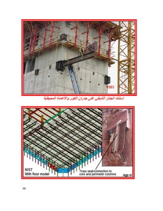
Three-Dimensional Model
A three-dimensional typical floor structural
model will be used for the study.
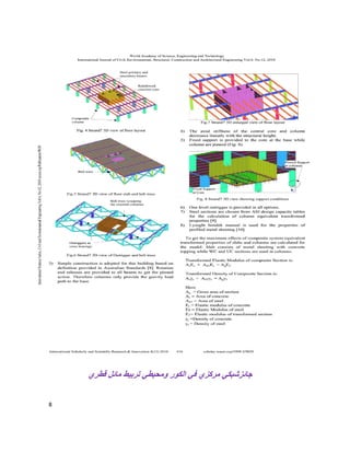
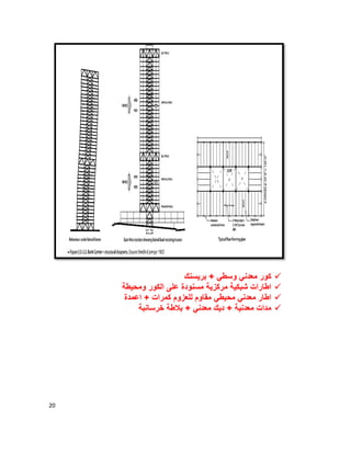
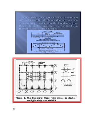
The model is a60-storey reinforced concrete consisting frame
atthe periphery and core wall in the center.
The building is viewed as an assemble of vertical
frames interconnected at each storey level by
diaphragm floor slab while the secondary beam
was considered as point load on main beam. The
static and dynamic computer analysis was
carried out using ETABS program [9].
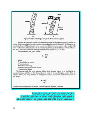
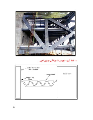
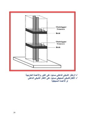
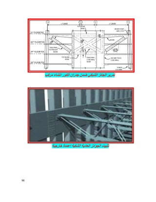
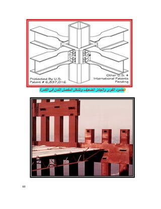
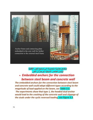
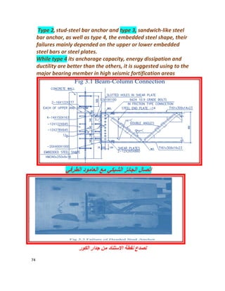
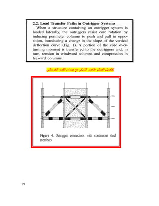
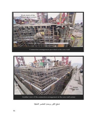
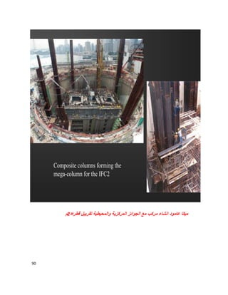
اﻟﻔراﻏﯾﺔ اﻟﺷﺑﻛﯾﺔ اﻟﺟواﺋز
وﺑﺷﻛل اﻟطﺎﺑﻖ ارﺗﻔﺎع ﻛﺎﻣل ﻋﻠﻰ ارﺗﻔﺎﻋﮭﺎ ﯾﻛونﺑوﻛس
ﻗطرﯾﺔ ﺗﺻﺎﻟب ﻋﻧﺎﺻر ﻣﻊﻋﺎﻣودﯾن ﺑﯾن ﯾﺻل ﻣﺗﺻﺎﻟب ﻗطري ﺑﺷﻛل او
واﻟﺳﻔﻠﻲ اﻟﻌﻠوي اﻟﺳﻘف ﺑﻼطﺔ وﺣﺎﻣﻠﺔ
ﻣﻌدﻧﯾﺔ ﺑﻣدادات ﻣدﻋم واﻟﺳﻘفﻛﯾردر ﻣﻌدﻧﯾﺔ ﻛﻣرات ﻋﻠﻰ ﻣﺳﻧودة
ﺧرﺳﺎﻧﺔ +ﺑﻼطﺔاﻷﻓﻘﻲ اﻟﻘوى ﻧﻘل ﻓﻲ ﺻﻠب ﻛدﯾﺎﻓرام ﺗﻌﻣل](https://image.slidesharecdn.com/outriggerbelttrussesdesign-160423022914/85/Outrigger-belt-trusses-design-37-320.jpg)
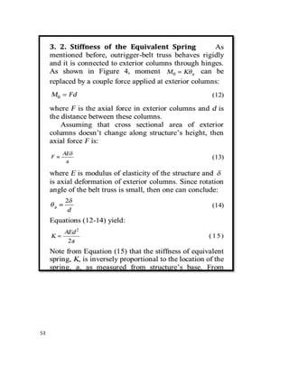
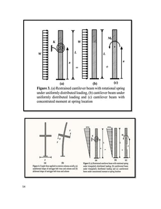
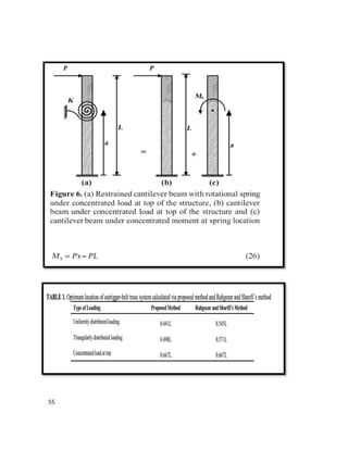
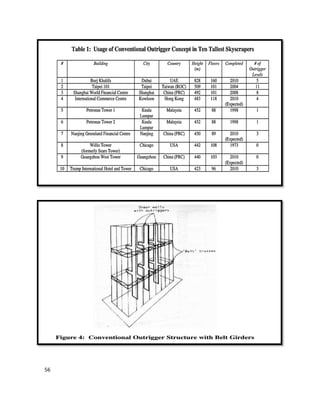
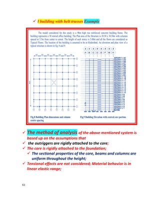
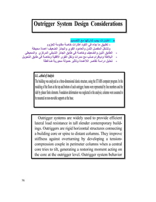


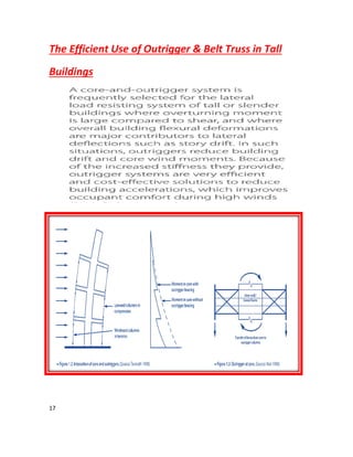
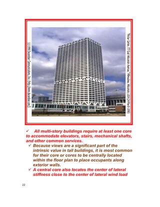
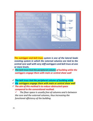
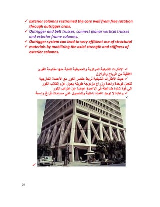
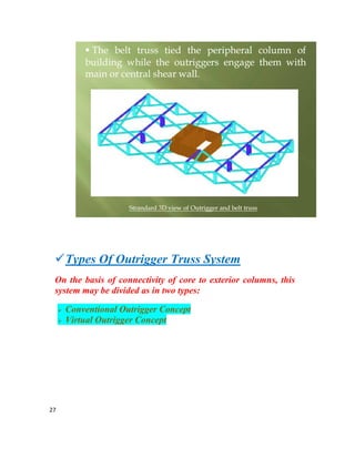
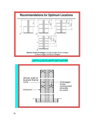
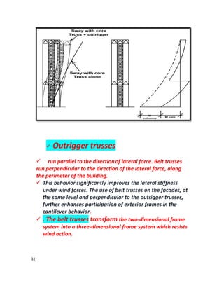
The document discusses the analysis of outrigger and belt truss systems in tall buildings, emphasizing their role in resisting lateral loads such as wind and earthquakes. It outlines the importance of design factors including strength, stiffness, and serviceability, and explains the effect of structural geometry on overall stability. Additionally, the document compares conventional and virtual outrigger concepts, highlighting their significance in enhancing building performance and reducing space obstructions.