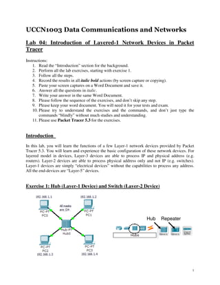
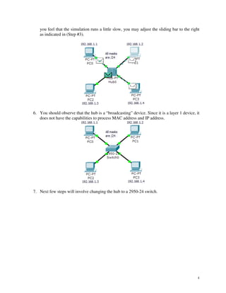
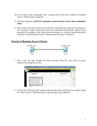
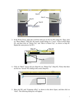
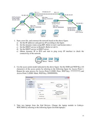
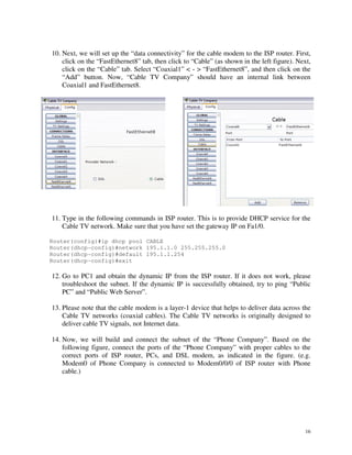
This document provides instructions for a lab exercise on networking devices in Packet Tracer. The exercises cover:
1. Using a hub and switch to observe the difference between layer 1 and layer 2 devices.
2. Using a repeater to extend the physical length of Ethernet communication.
3. Configuring wireless access points and connecting laptops to the wireless network.
4. Constructing a network with cable and DSL modems connecting clients to an ISP router, to demonstrate layer 1 connectivity over coaxial cables and phone lines.
This document provides instructions for a lab involving analysis of network protocols using Wireshark. The lab consists of 10 exercises:
1. Performing a ping to a server while capturing traffic with Wireshark.
2. Performing a trace route to a website while capturing traffic.
3. Port scanning the server while capturing traffic.
4. Performing DNS lookups of a website while capturing traffic.
5. Releasing and renewing the DHCP client IP address while capturing traffic.
6. Accessing an FTP server through a web browser while capturing traffic.
7. Accessing the FTP server through commands while capturing traffic.
8. Telnetting to the
University of Virginia
cs4414: Operating Systems
http://rust-class.org
For embedded notes, see:
http://rust-class.org/class-22-microkernels-and-beyond.html
This document provides an overview of Contiki and its event-driven kernel, processes, protothreads, timers, and communication stack. It discusses how Contiki uses protothreads to provide sequential flow of control in an event-driven environment. It also summarizes the different types of timers in Contiki and provides an example of how to communicate using Rime, Contiki's networking stack.
The document discusses recent improvements to numeric handling in Python, particularly the new float representation (repr) introduced in Python 2.7. The new repr aims to produce the shortest decimal string that rounds back to the original float value, satisfying constraints of accuracy and consistency. It uses adapted C code that performs correctly rounded conversions between decimal strings and floating point values. The new repr is friendlier for beginners and reduces discrepancies between platforms.
cs4414: Operating Systems
http://rust-class.org/class-1-what-is-an-operating-system.html
Class 1: What is an Operating System?
Why so many programming languages?
Introducing Rust
Contiki introduction II-from what to howDingxin Xu
The document discusses the Contiki operating system framework, including how it uses processes and events for scheduling work, inter-process communication using event posting, and how modules like Rime and the TDMA MAC layer separate protocol logic from header construction and buffer management for flexible networking implementations. Key data structures include a process list and event queue that the kernel uses to schedule work across asynchronous processes.
This paper aims to make students become familiar with the UNIX environment, developing programming skills in C, to increase their exposure to a shell functionality and put into practice concepts of management processes.
Accumulo 1.4 & 1.5 introduce improvements to RFile indexing and caching that speed up random access and scanning. The multi-level indexing stores index blocks at different levels to reduce memory usage during writes. The FATE system provides fault tolerance for concurrent table operations. Table cloning, range operations, and logical timestamps for bulk import are also new features.
Learning Python through Minecraft on the Raspberry Pi - WorksheetsManchesterBudo
This document provides instructions for 8 tasks related to programming in Python and Minecraft Pi. It outlines the steps to complete each task, with the goals being to practice file handling, typing, looping, sleeping, moving players, using 3D coordinates, variables, if statements, building, coloring blocks, and communicating between Minecraft and Python.
Connecting morse key to pc using an optical mouse.Parvesh Taneja
This document provides instructions for connecting a Morse key to a PC using an optical mouse. It outlines two methods: using a DB9 to USB converter or hacking an optical mouse. Hacking the mouse is described as the cheaper and easier option. A step-by-step procedure is provided that involves opening the mouse, identifying the micro-buttons and LED, and wiring the key to trigger the buttons to send keyboard signals. Optional additions like LED indicators are also described.
In this session IOT expert Bob Gallup walked us through the basics of electronics and taught us how to do some basic wiring and programming on an Adafruit Trinket micro processor.
The document describes an experiment to create 4 local area networks (LANs) with different IP addresses and subnets. It involves drawing switches on a network diagram using Cisco Packet Tracer and connecting 10 computers and a laptop to each switch using either straight-through or cross-over cables. The key steps are to configure unique IP addresses on each laptop by selecting the desktop tab and entering the IP address and subnet mask in the IP configuration dialog box. Once set up, the goal is to test connectivity between devices by using the ping command.
This document contains instructions for 6 programming practices using an mBot robot. Practice 1 teaches how to program the robot to avoid obstacles using an ultrasonic sensor. Practice 2 explains how to control the robot's RGB LED lights by varying color values. Practice 3 demonstrates how to program the robot to play musical notes. Practice 4 shows how to make the robot follow a flashlight by responding to light sensor input. Practice 5 provides directions for programming line following behavior. Practice 6 describes measuring temperature with the robot's onboard sensor.
Customizable Microprocessor design on Nexys 3 Spartan FPGA BoardBharat Biyani
This document describes a customizable microprocessor design created by students at the University of Texas at Dallas. The microprocessor has three main blocks: a keyboard reader for input, a microprocessor unit for processing, and a VGA controller for output display. It implements a RISC architecture with a 16-bit data bus, 12-bit address bus, and 22 instructions. The microprocessor can operate in different modes including programming, execution, and debug modes. It also includes novel features such as real-time register display, flexibility to write to any memory location, and ability to reprogram itself without reloading the bitfile.
This document provides instructions for a lab activity involving configuring networking devices. The activity includes 7 parts where students will physically connect a router, switch, and computers, and then configure the devices by following instructions. The objectives are to practice physical connectivity, establishing console sessions on devices, assigning IP addresses for static routing, and verifying configurations and connectivity. Diagrams and tables are provided to identify device interfaces, cable types, and IP addressing schemes.
This document provides instructions for configuring various end devices in Packet Tracer, including a server, two PCs, and a switch. Students are asked to:
1. Build a network topology connecting a server, two PCs, and a switch.
2. Configure IP addresses on the server, PC0, and PC1, then validate the connections by pinging between devices and accessing the server web page from PC1.
3. Access the switch CLI and change the switch name, then shut down two interfaces to disable those connections.
Screenshots should be provided showing the completion of each step.
File 1 proteus tutorial for digital circuit designSanjeev Singh
This document provides instructions for using Proteus software to simulate and design digital circuits. It discusses:
1) The objectives of learning to use Proteus software to simulate designed digital circuits and understand how to apply digital logic equations to hardware designs.
2) How to use tools in Proteus like parts browsing, power supplies, input generators, and logic state components.
3) How to simulate circuits by placing components, wiring them, and using logic probes or waveform displays to view output measurements.
4) Some example assignments involving creating circuits from logic equations and comparing/reducing equations, and plotting input-output relationships.
Switch Control and Time Delay
1. LEDs and switches
2. Keypad and LEDs
3. Keypad and 8-segment LED C language and Assembly Code for Freescale MC9S08AW60
This document provides an overview of common computer components and their troubleshooting, including:
- The CPU and its functions as the central processing unit that executes instructions. Troubleshooting steps are outlined for issues like no power.
- Common computer peripherals like monitors, keyboards, mice, and printers. Block diagrams show the components and potential issues covered include no video signal, keys not working, cursor issues, and printers not powering on.
- Other devices like UPS systems are introduced and freezing or crashing issues are addressed with solutions like using Ctrl-Alt-Del and safe boot modes. Basic maintenance tips are provided like periodic reboots and avoiding dust.
This document provides an overview of the content and assignments for ECET 340 Entire Course. It lists the weekly homework assignments, labs, and objectives for ECET 340 over 7 weeks. The document includes sample homework questions on topics like interrupts, timers, analog-to-digital conversion, and serial communication. It also provides examples of lab objectives and steps for labs covering these topics.
This document provides instructions for a lab on protocols in Packet Tracer. It outlines 27 exercises to observe protocols like ICMP, ARP, and DHCP. Students are instructed to perform each lab step, record results, and answer questions to better understand how protocols work and are used in networking. The introduction provides background on protocols and their role in defining procedures for transmitting and receiving data between networked devices.
This document discusses interfacing a hex keypad to an AT89C51 microcontroller. It provides details on the components required, including the microcontroller, keypad, and 7-segment display. It describes how the keypad is scanned using column scanning to detect key presses and determine the pressed key. The programming for the microcontroller is also outlined, showing how it initializes ports, scans the keypad, looks up the pressed key in a lookup table to display on the 7-segment display. Potential issues faced include debouncing and directly powering the display. Future work proposed includes adding an LCD module to create a basic calculator.
The document provides a history of computers from early counting aids to modern personal computers. It describes the development of binary numbering systems and components of early computers like the Analytical Engine, ENIAC, and UNIVAC. It also discusses basic computer concepts like data storage, processing units, algorithms, programming, and hardware/software components.
1. This document discusses configuring a basic local area network (LAN) in Packet Tracer, including adding a switch, PCs, server, and router.
2. Key steps include connecting the devices, configuring IP addresses on each (static or dynamic via DHCP), and testing connectivity between devices via ping.
3. The router interface IP becomes the default gateway for devices on the LAN, and the DHCP service is configured to assign IPs and the router as gateway to allow dynamic addressing.
ABC Consolidated Financial InfoABC Companys current financial inf.docxransayo
ABC Consolidated Financial InfoABC Company's current financial information (before/without expansion)Dec. 31,20X2Dec. 31,20X1Cash$ 50,000$ 70,000Accounts receivable (net)$ 120,000$ 180,000Merchandise inventory$ 350,000$ 280,000Property plant, & equipment$ 400,000$ 300,000Less: Accumulated depreciation$ (170,000)$ (100,000)Total assets$ 750,000$ 730,000Accounts payable$ 250,000$ 210,000Income taxes payable$ 40,000$ 10,000Common stock$ 240,000$ 240,000Retained earnings$ 220,000$ 270,000Total liabilities & stock, equity$ 750,000$ 730,000The firm's accrual-basis income statement revealed the following data:Sales$ 1,200,000Cost of goods sold$ 800,000selling and administrative expenses$ 250,000Depreciation expense$ 70,000Income taxes$ 30,000Dividends declared and paid during 20X2$ 100,000ABC purchased $100,000 of equipment for cash on August 14, 20X2(There was no interest expense.)
ABC Product informationBased on Chapter 5's exercise 5ABC's Product informationCurrent ProductExpansion Product (estimate)Selling Price$14.50?Units produced and expected to be sold80,0005,000Machine Hours40,0005,000Direct Materials$1.30 per unit$5.60 per unitDirect labor dollars needed per product$2.80 per unit$4.00 per unitVariable Factory Overhead$1.00 per Machine Hour$1.00 per Machine HourVariable Selling Expense$0.20 per unit$0.20 per unitTotal Fixed Costs:Fixed Factory Overhead$ 198,000Fixed Selling expenses$ 191,250
UNIVERSITY OF CALIFORNIA, SANTA CRUZ
BOARD OF STUDIES IN COMPUTER ENGINEERING
CMPE13/L: INTRODUCTION TO PROGRAMMING IN C
Lab 1: Compiling, Running, and Debugging
Introduction
This is the first lab in CMPE13. Here we will demonstrate the basics of compiling and running C
programs in the simulator and on the Uno32 hardware. We will also explore the tools we will
use and some of their features for debugging problems you might encounter.
Reading
• Document on compiler errors
• Document on Unix and Git
• Document on software installation (if you want to run everything on your own computer)
• Document on style guidelines
• Document on MPLAB X
• Document on serial communications
• K&R Preface and Introduction
• K&R Sections 1.0-1.2, 4.5, 4.11
Provided Files
• part1.c: This file contains code that performs a simple sorting algorithm on five randomly
generated numbers. Follow the setup procedures listed below, add the requested
documentation, and format the code to follow the provided style guidelines.
• part2.c: This file contains an empty main() to be filled with the exercises from section 1.2 of
K&R. In addition, you will be asked to modify these exercises to add some additional
functionality. Detailed steps are listed below.
• BOARD.c/h - Contains initialization code for the UNO32 along with standard #defines and
system libraries used. Also includes the standard fixed-width datatypes and error return values.
You will not be modifying these fi.
This document describes interfacing an LCD display and keyboard to an 8051 microcontroller. It discusses connecting the LCD to output pins of the microcontroller to control the display. Commands are sent to initialize and update the LCD. A similar process of scanning rows and columns is used to interface a 4x4 keyboard matrix and detect which key is pressed by checking for a closed row and column. The document provides code examples to write characters to the LCD and scan the keyboard to identify pressed keys.
This document describes a parking meter design project implemented using an LPC2378 microprocessor, LCD display, keypad, and LEDs. The project allows a user to select a parking space using the keypad, displays the selection and remaining time on the LCD, and lights the corresponding LED. The design includes hardware components, schematics, specifications, state diagrams, and photos of the working system displaying initial messages, prompts for input, and countdown timers. Completing the project required integrating hardware, software, and addressing issues with connecting components.
The document summarizes an introduction meeting to Unity3D game engine. It discusses what a game engine is and how Unity manages entities and subsystems. It then walks through exercises having attendees create and modify a spinning cube prefab to demonstrate core Unity concepts like hierarchies, components and scripting basics. The document stresses that the goal is to understand how to learn and explore Unity rather than fully learning game development.
The document provides an overview of cryptography concepts including encryption, decryption, symmetric cryptosystems, block ciphers, substitution ciphers, the one-time pad, and algorithms such as DES, Triple DES, AES, and others. Key points covered include Kerckhoffs's principle of keeping algorithms public and keys private, how symmetric encryption works between two parties with a shared key, methods of encrypting plaintext in blocks or as a bit stream, techniques like substitution and transposition ciphers, weaknesses of approaches like the Hill cipher, and the history and operation of standard block ciphers.
The document defines information security and discusses its history and key concepts. It outlines the evolution of information security from physical security controls to modern approaches addressing confidentiality, integrity, and availability of information. Key aspects covered include definitions of security, the CIA triad/diamond models, cryptography, access control models, and digital signatures.
More Related Content
Similar to Uccn1003 -may10_-_lab_04_-_intro_to_layer-1_network_devices-updated_30_june2010-2
Learning Python through Minecraft on the Raspberry Pi - WorksheetsManchesterBudo
This document provides instructions for 8 tasks related to programming in Python and Minecraft Pi. It outlines the steps to complete each task, with the goals being to practice file handling, typing, looping, sleeping, moving players, using 3D coordinates, variables, if statements, building, coloring blocks, and communicating between Minecraft and Python.
Connecting morse key to pc using an optical mouse.Parvesh Taneja
This document provides instructions for connecting a Morse key to a PC using an optical mouse. It outlines two methods: using a DB9 to USB converter or hacking an optical mouse. Hacking the mouse is described as the cheaper and easier option. A step-by-step procedure is provided that involves opening the mouse, identifying the micro-buttons and LED, and wiring the key to trigger the buttons to send keyboard signals. Optional additions like LED indicators are also described.
In this session IOT expert Bob Gallup walked us through the basics of electronics and taught us how to do some basic wiring and programming on an Adafruit Trinket micro processor.
The document describes an experiment to create 4 local area networks (LANs) with different IP addresses and subnets. It involves drawing switches on a network diagram using Cisco Packet Tracer and connecting 10 computers and a laptop to each switch using either straight-through or cross-over cables. The key steps are to configure unique IP addresses on each laptop by selecting the desktop tab and entering the IP address and subnet mask in the IP configuration dialog box. Once set up, the goal is to test connectivity between devices by using the ping command.
This document contains instructions for 6 programming practices using an mBot robot. Practice 1 teaches how to program the robot to avoid obstacles using an ultrasonic sensor. Practice 2 explains how to control the robot's RGB LED lights by varying color values. Practice 3 demonstrates how to program the robot to play musical notes. Practice 4 shows how to make the robot follow a flashlight by responding to light sensor input. Practice 5 provides directions for programming line following behavior. Practice 6 describes measuring temperature with the robot's onboard sensor.
Customizable Microprocessor design on Nexys 3 Spartan FPGA BoardBharat Biyani
This document describes a customizable microprocessor design created by students at the University of Texas at Dallas. The microprocessor has three main blocks: a keyboard reader for input, a microprocessor unit for processing, and a VGA controller for output display. It implements a RISC architecture with a 16-bit data bus, 12-bit address bus, and 22 instructions. The microprocessor can operate in different modes including programming, execution, and debug modes. It also includes novel features such as real-time register display, flexibility to write to any memory location, and ability to reprogram itself without reloading the bitfile.
This document provides instructions for a lab activity involving configuring networking devices. The activity includes 7 parts where students will physically connect a router, switch, and computers, and then configure the devices by following instructions. The objectives are to practice physical connectivity, establishing console sessions on devices, assigning IP addresses for static routing, and verifying configurations and connectivity. Diagrams and tables are provided to identify device interfaces, cable types, and IP addressing schemes.
This document provides instructions for configuring various end devices in Packet Tracer, including a server, two PCs, and a switch. Students are asked to:
1. Build a network topology connecting a server, two PCs, and a switch.
2. Configure IP addresses on the server, PC0, and PC1, then validate the connections by pinging between devices and accessing the server web page from PC1.
3. Access the switch CLI and change the switch name, then shut down two interfaces to disable those connections.
Screenshots should be provided showing the completion of each step.
File 1 proteus tutorial for digital circuit designSanjeev Singh
This document provides instructions for using Proteus software to simulate and design digital circuits. It discusses:
1) The objectives of learning to use Proteus software to simulate designed digital circuits and understand how to apply digital logic equations to hardware designs.
2) How to use tools in Proteus like parts browsing, power supplies, input generators, and logic state components.
3) How to simulate circuits by placing components, wiring them, and using logic probes or waveform displays to view output measurements.
4) Some example assignments involving creating circuits from logic equations and comparing/reducing equations, and plotting input-output relationships.
Switch Control and Time Delay
1. LEDs and switches
2. Keypad and LEDs
3. Keypad and 8-segment LED C language and Assembly Code for Freescale MC9S08AW60
This document provides an overview of common computer components and their troubleshooting, including:
- The CPU and its functions as the central processing unit that executes instructions. Troubleshooting steps are outlined for issues like no power.
- Common computer peripherals like monitors, keyboards, mice, and printers. Block diagrams show the components and potential issues covered include no video signal, keys not working, cursor issues, and printers not powering on.
- Other devices like UPS systems are introduced and freezing or crashing issues are addressed with solutions like using Ctrl-Alt-Del and safe boot modes. Basic maintenance tips are provided like periodic reboots and avoiding dust.
This document provides an overview of the content and assignments for ECET 340 Entire Course. It lists the weekly homework assignments, labs, and objectives for ECET 340 over 7 weeks. The document includes sample homework questions on topics like interrupts, timers, analog-to-digital conversion, and serial communication. It also provides examples of lab objectives and steps for labs covering these topics.
This document provides instructions for a lab on protocols in Packet Tracer. It outlines 27 exercises to observe protocols like ICMP, ARP, and DHCP. Students are instructed to perform each lab step, record results, and answer questions to better understand how protocols work and are used in networking. The introduction provides background on protocols and their role in defining procedures for transmitting and receiving data between networked devices.
This document discusses interfacing a hex keypad to an AT89C51 microcontroller. It provides details on the components required, including the microcontroller, keypad, and 7-segment display. It describes how the keypad is scanned using column scanning to detect key presses and determine the pressed key. The programming for the microcontroller is also outlined, showing how it initializes ports, scans the keypad, looks up the pressed key in a lookup table to display on the 7-segment display. Potential issues faced include debouncing and directly powering the display. Future work proposed includes adding an LCD module to create a basic calculator.
The document provides a history of computers from early counting aids to modern personal computers. It describes the development of binary numbering systems and components of early computers like the Analytical Engine, ENIAC, and UNIVAC. It also discusses basic computer concepts like data storage, processing units, algorithms, programming, and hardware/software components.
1. This document discusses configuring a basic local area network (LAN) in Packet Tracer, including adding a switch, PCs, server, and router.
2. Key steps include connecting the devices, configuring IP addresses on each (static or dynamic via DHCP), and testing connectivity between devices via ping.
3. The router interface IP becomes the default gateway for devices on the LAN, and the DHCP service is configured to assign IPs and the router as gateway to allow dynamic addressing.
ABC Consolidated Financial InfoABC Companys current financial inf.docxransayo
ABC Consolidated Financial InfoABC Company's current financial information (before/without expansion)Dec. 31,20X2Dec. 31,20X1Cash$ 50,000$ 70,000Accounts receivable (net)$ 120,000$ 180,000Merchandise inventory$ 350,000$ 280,000Property plant, & equipment$ 400,000$ 300,000Less: Accumulated depreciation$ (170,000)$ (100,000)Total assets$ 750,000$ 730,000Accounts payable$ 250,000$ 210,000Income taxes payable$ 40,000$ 10,000Common stock$ 240,000$ 240,000Retained earnings$ 220,000$ 270,000Total liabilities & stock, equity$ 750,000$ 730,000The firm's accrual-basis income statement revealed the following data:Sales$ 1,200,000Cost of goods sold$ 800,000selling and administrative expenses$ 250,000Depreciation expense$ 70,000Income taxes$ 30,000Dividends declared and paid during 20X2$ 100,000ABC purchased $100,000 of equipment for cash on August 14, 20X2(There was no interest expense.)
ABC Product informationBased on Chapter 5's exercise 5ABC's Product informationCurrent ProductExpansion Product (estimate)Selling Price$14.50?Units produced and expected to be sold80,0005,000Machine Hours40,0005,000Direct Materials$1.30 per unit$5.60 per unitDirect labor dollars needed per product$2.80 per unit$4.00 per unitVariable Factory Overhead$1.00 per Machine Hour$1.00 per Machine HourVariable Selling Expense$0.20 per unit$0.20 per unitTotal Fixed Costs:Fixed Factory Overhead$ 198,000Fixed Selling expenses$ 191,250
UNIVERSITY OF CALIFORNIA, SANTA CRUZ
BOARD OF STUDIES IN COMPUTER ENGINEERING
CMPE13/L: INTRODUCTION TO PROGRAMMING IN C
Lab 1: Compiling, Running, and Debugging
Introduction
This is the first lab in CMPE13. Here we will demonstrate the basics of compiling and running C
programs in the simulator and on the Uno32 hardware. We will also explore the tools we will
use and some of their features for debugging problems you might encounter.
Reading
• Document on compiler errors
• Document on Unix and Git
• Document on software installation (if you want to run everything on your own computer)
• Document on style guidelines
• Document on MPLAB X
• Document on serial communications
• K&R Preface and Introduction
• K&R Sections 1.0-1.2, 4.5, 4.11
Provided Files
• part1.c: This file contains code that performs a simple sorting algorithm on five randomly
generated numbers. Follow the setup procedures listed below, add the requested
documentation, and format the code to follow the provided style guidelines.
• part2.c: This file contains an empty main() to be filled with the exercises from section 1.2 of
K&R. In addition, you will be asked to modify these exercises to add some additional
functionality. Detailed steps are listed below.
• BOARD.c/h - Contains initialization code for the UNO32 along with standard #defines and
system libraries used. Also includes the standard fixed-width datatypes and error return values.
You will not be modifying these fi.
This document describes interfacing an LCD display and keyboard to an 8051 microcontroller. It discusses connecting the LCD to output pins of the microcontroller to control the display. Commands are sent to initialize and update the LCD. A similar process of scanning rows and columns is used to interface a 4x4 keyboard matrix and detect which key is pressed by checking for a closed row and column. The document provides code examples to write characters to the LCD and scan the keyboard to identify pressed keys.
This document describes a parking meter design project implemented using an LPC2378 microprocessor, LCD display, keypad, and LEDs. The project allows a user to select a parking space using the keypad, displays the selection and remaining time on the LCD, and lights the corresponding LED. The design includes hardware components, schematics, specifications, state diagrams, and photos of the working system displaying initial messages, prompts for input, and countdown timers. Completing the project required integrating hardware, software, and addressing issues with connecting components.
The document summarizes an introduction meeting to Unity3D game engine. It discusses what a game engine is and how Unity manages entities and subsystems. It then walks through exercises having attendees create and modify a spinning cube prefab to demonstrate core Unity concepts like hierarchies, components and scripting basics. The document stresses that the goal is to understand how to learn and explore Unity rather than fully learning game development.
Similar to Uccn1003 -may10_-_lab_04_-_intro_to_layer-1_network_devices-updated_30_june2010-2 (20)
The document provides an overview of cryptography concepts including encryption, decryption, symmetric cryptosystems, block ciphers, substitution ciphers, the one-time pad, and algorithms such as DES, Triple DES, AES, and others. Key points covered include Kerckhoffs's principle of keeping algorithms public and keys private, how symmetric encryption works between two parties with a shared key, methods of encrypting plaintext in blocks or as a bit stream, techniques like substitution and transposition ciphers, weaknesses of approaches like the Hill cipher, and the history and operation of standard block ciphers.
The document defines information security and discusses its history and key concepts. It outlines the evolution of information security from physical security controls to modern approaches addressing confidentiality, integrity, and availability of information. Key aspects covered include definitions of security, the CIA triad/diamond models, cryptography, access control models, and digital signatures.
The document provides an overview of aggregate demand and aggregate supply models in economics. It defines aggregate demand and supply curves, and explains how each curve is derived. The aggregate demand curve slopes downward, as the price level and real GDP are inversely related due to interest rate, wealth, and trade effects. The aggregate supply curve slopes upward in the short-run due to sticky wages and prices. Shifts in aggregate demand and supply curves can occur due to changes in consumption, investment, government spending, net exports, technology or costs.
This chapter discusses fiscal and monetary policy. It defines the multiplier effect as the ratio of change in output to a change in autonomous spending. An expansionary fiscal policy increases government spending or cuts taxes to stimulate the economy, while a contractionary policy decreases spending or raises taxes to curb inflation. Monetary policy involves changing interest rates and the money supply. An expansionary policy raises the money supply to boost output, while a contractionary policy lowers the money supply to reduce inflation. The chapter also discusses crowding-out, where higher government spending raises interest rates and lowers private investment.
The document defines key macroeconomic concepts including aggregate expenditure, output, income, consumption, saving, investment, government spending, taxes, imports, exports, and equilibrium. It also discusses the consumption function, marginal propensity to consume, marginal propensity to save, and the multiplier effect.
The document provides an overview of key economic concepts related to measuring national output and income. It defines Gross Domestic Product (GDP) as the total market value of all final goods and services produced within a country in a given period. GDP can be calculated using the expenditure approach (summing consumption, investment, government spending, and net exports) or the income approach (summing compensation, profits, rents, and other incomes). It also defines Gross National Product (GNP) and related terms and discusses limitations of using GDP as a measure.
This document provides an introduction to macroeconomics. It discusses the key components and concerns of macroeconomics including inflation, output growth, unemployment, and income distribution. It also covers aggregate demand and supply, the circular flow model, and the roles of households, firms, government and the international sector in the macroeconomy. Government policies aim to achieve price stability, economic growth, full employment, and an equitable distribution of income.
This document provides an overview of key concepts in market structure, including monopolistic competition and oligopoly. It discusses the characteristics of monopolistic competition, including differentiated products, free entry and exit, and firms as price takers. It also covers the short-run and long-run equilibrium of firms under monopolistic competition. For oligopoly, it defines the structure and discusses interdependent behavior among a small number of large firms, barriers to entry, and the use of game theory to analyze strategic interactions.
The document summarizes key concepts about monopoly market structure:
1) A monopoly is characterized by a single seller, significant barriers to entry, and no close substitutes for the product. It faces a downward-sloping demand curve and can influence prices.
2) In the short-run, a monopoly will produce where marginal revenue equals marginal cost to maximize profits, earning normal profits, supernormal profits, or losses.
3) In the long-run, the monopoly may adjust its scale of production to maximize profits or minimize losses. It can earn economic profits but also imposes social costs like deadweight loss.
4) The document also discusses price discrimination, where a monopoly charges different prices for
This chapter discusses perfect competition and profit maximization in perfect competition. It contains the following key points:
1. Under perfect competition, there are many small firms and buyers/sellers, homogeneous products, free entry and exit, and perfect information. Firms are price takers and maximize profits by producing where MR=MC.
2. In the short run, firms will shut down if P<AVC or operate to minimize losses if ATC>P>AVC. In the long run, zero economic profits are achieved through free entry and exit of firms.
3. External changes like shifting demand curves or new technology can impact market equilibrium prices and quantities in the short and long run through adjustments to
1. The document discusses the production process of firms, including the concepts of production, costs, and profit maximization.
2. It explains that production involves transforming inputs into outputs using factors of production, with the goal of firms being to maximize profits.
3. The production process involves decisions about how much output to supply, which production technology to use, and how much of each input to demand.
The document provides an overview of market efficiency and elasticity concepts. It defines key terms like equilibrium, supply and demand, market failure due to imperfect competition, public goods, externalities and imperfect information. It also discusses government intervention through price ceilings, price floors, rationing and other restrictions. It explains the concepts of consumer surplus, producer surplus and deadweight loss. Finally, it defines different types of elasticity including price elasticity of demand, income elasticity of demand, cross price elasticity of demand and price elasticity of supply.
This document provides an overview of demand, supply, and market equilibrium concepts. It defines key terms like demand curve, supply curve, equilibrium price and quantity. It explains how shifts in demand or supply curves affect equilibrium. Specifically:
1) The law of demand and supply are introduced, which state that quantity demanded increases with lower price and quantity supplied increases with higher price.
2) Market equilibrium exists when quantity demanded equals quantity supplied. Disequilibrium can cause surplus or shortage.
3) A shift of the demand or supply curve changes the equilibrium price and quantity in the market. Both curves shifting can have varying effects depending on the direction and magnitude of the shifts.
The document provides an overview of key economic concepts including:
1) Economics is defined as the study of how people use limited resources to fulfill unlimited wants. It involves choices under scarcity.
2) Microeconomics studies individual units like households and firms. Macroeconomics looks at the whole economy in terms of outputs, prices, and employment.
3) The production possibilities frontier (PPF) curve shows the maximum combinations of two goods an economy can produce with full employment of resources. Points inside the curve are attainable but inefficient, while points outside are unattainable.
This document summarizes key concepts in international trade and exchange rates discussed in Chapter 13. It covers absolute and comparative advantage, types of trade barriers, components of the balance of payments, and exchange rate systems. Country A has an absolute advantage in cars and Country B has an advantage in rice, but Country B has a lower opportunity cost of cars, so it should specialize in car production. The current account records trade in goods, services, income, and transfers. Exchange rates can be fixed, flexible, or managed to balance trade and stability.
This document provides an overview of international trade and exchange rates. It discusses absolute and comparative advantage, types of trade barriers, components of the balance of payments, and exchange rate systems. Absolute advantage refers to the ability to produce more of a good using fewer resources, while comparative advantage means a good can be produced at lower opportunity cost. Trade barriers include tariffs, quotas, export subsidies, and embargoes. The balance of payments records transactions in goods, services, and assets between a country and the rest of the world. Exchange rates can be fixed, flexible, or managed floating.
This chapter discusses fiscal and monetary policy. It defines the multiplier effect as the ratio of change in output to a change in autonomous spending. An expansionary fiscal policy increases government spending or cuts taxes to boost output, while a contractionary policy decreases spending or raises taxes. Monetary policy involves changing interest rates and the money supply via tools like open market operations. Both expansionary and contractionary monetary policies aim to respectively increase or decrease output. The crowding-out effect refers to how increased government spending may raise interest rates and reduce private investment.
The document defines key macroeconomic concepts including aggregate expenditure, output, income, consumption, saving, investment, government spending, taxes, imports, exports, and equilibrium. It also discusses the consumption function, marginal propensity to consume, marginal propensity to save, and the multiplier effect.
The document provides an overview of key economic concepts related to measuring national output and income, including:
1) It defines Gross Domestic Product (GDP) as the total market value of all final goods and services produced within a country in a given period. GDP is calculated using the expenditure and income approaches.
2) The expenditure approach sums consumer spending (C), private investment (I), government spending (G), and net exports (X-M). The income approach sums wages, rents, profits, and other factor incomes.
3) Gross National Product (GNP) differs from GDP by including income from domestic factors working abroad, less income to foreign factors working domestically.
4) Real
This document provides an overview of market structures including monopolistic competition and oligopoly. It discusses key characteristics of each structure such as product differentiation, barriers to entry, and interdependence between firms. The document also covers concepts like profit maximization, loss minimization, long-run equilibrium, price rigidity, game theory, and Nash equilibrium which are important for understanding firm behavior under different market conditions.
1. UCCN1003 Data Communications and Networks
Lab 04: Introduction of Layered-1 Network Devices in Packet
Tracer
Instructions:
1. Read the “Introduction” section for the background.
2. Perform all the lab exercises, starting with exercise 1.
3. Follow all the steps.
4. Record the results in all italic bold actions (by screen capture or copying).
5. Paste your screen captures on a Word Document and save it.
6. Answer all the questions in italic.
7. Write your answer in the same Word Document.
8. Please follow the sequence of the exercises, and don’t skip any step.
9. Please keep your word document. You will need it for your tests and exam.
10. Please try to understand the exercises and the commands, and don’t just type the
commands “blindly” without much studies and understanding.
11. Please use Packet Tracer 5.3 for the exercises.
Introduction
In this lab, you will learn the functions of a few Layer-1 network devices provided by Packet
Tracer 5.3. You will learn and experience the basic configuration of these network devices. For
layered model in devices, Layer-3 devices are able to process IP and physical address (e.g.
routers). Layer-2 devices are able to process physical address only and not IP (e.g. switches).
Layer-1 devices are simply “electrical devices” without the capabilities to process any address.
All the end-devices are “Layer-5” devices.
Exercise 1: Hub (Layer-1 Device) and Switch (Layer-2 Device)
Hub Repeater
1
2. 1. Construct the above networks with 1 hub and 4 PCs. Put in the IP addresses and subnet
masks in the PCs as indicated in the above figure.
Step #4
Step #3
Step #2
Step #1
2. Click on “Simulation mode” (Step #1). Then “Edit Filters” button (Step #2). Click to
uncheck “Show All/None” (Step #3), this step makes all the ‘√’ disappear. Click to
check ICMP (Step #4). Click anywhere else to hide the “Edit ACL Filters” dialog box.
All these steps are to create a “simulation mode” to observe ping operation (ICMP).
2
3. Step #4
Step #5
Step #3
Step #2 Step #1
3. Click on the “sealed envelope with a +” button (Step #1). The mouse button will
change from an arrow to an envelope. Click on PC2 (192.168.1.3) (Step #2), and then
click on PC1 (192.168.1.2) (Step #3). This step means PC2 is trying to ping PC1.
4. The line shown in “Step #4” appears. Click on “Capture/Forward” button (Step #5) and
observe the envelope as it travels. You need to click the “Capture/Forward” button a few
times and continue to observe the envelope.
Step #1
Step #2
Step #3
5. The simulation finishes as you see the “envelope with a √” in PC2. Repeat the
simulation by clicking the “Reset Simulation” buttion (Step #1). Click on “Auto Capture /
Play” button (Step #2). After Step #2, the envelope will automatically travels by itself. If
3
4. you feel that the simulation runs a little slow, you may adjust the sliding bar to the right
as indicated in (Step #3).
6. You should observe that the hub is a “broadcasting” device. Since it is a layer 1 device, it
does not have the capabilities to process MAC address and IP address.
7. Next few steps will involve changing the hub to a 2950-24 switch.
4
5. Step #2
Step #3
Step #1
8. Click on “Realtime mode” button (Step #1). In “Simulation mode”, time is frozen. Click
on the “X” button (Step #2) to erase the hub and change it to a switch as shown in (Step
#3). Remember to re-wire the PCs to the switch. Wait until all the “bubbles” turn green.
9. Click on “Simulation mode” again. Click on “Auto Capture / Play” and observe the
envelope. After the simulation finishes, you may click on the “ping envelope” and then
click on PC3 and PC0 to simulate PC3 is trying to ping PC0. Repeat the procedure of
“Auto Capture / Play” to observe the envelope.
Step #2
Step #1
5
6. 10. If you want to erase a particular “pair” of ping. Click on the line of (Step #1) and then
click on “Delete button” (Step #2).
11. After the simulation, ALWAYS remember to put the Packet Tracer back to Realtime
mode.
12. Note: Switch only does broadcast at the first run. After that, the switch will not operate in
the “broadcast” mode, because the switch has remembered all the MAC addresses that
attached to its interfaces. The switch from this moment on, will only send the data from
source PC to destination PC directly. Whereas hub will always “broadcast”.
Exercise 2: Repeater (Layer-1 Device)
1. Start a new file and construct the above network. Ping PC1 from PC0 to ensure
connectivity among the two PCs.
Step #1 Step #2
2. Click on the “Physical mode” button at the top left corner of Packet Trace window (Step
#1). Then, click on “Working Closet” at the top right corner (Step #2).
6
7. Step #2
Step #1
Step #3
Step #4
3. In the Work Closet, adjust the scroll bar until you see the two PCs (Step #1). Then, click
on “Move Object” (Step #2), the mouse would change to a “cross”. Click on PC0 (Step
#3), and then click on “Home City” and “Move to Home City”, as shown in Step #4.
Repeat the same process for PC1.
Step #1 Step #2
Step #3
4. Click on “Back” (twice) till you (Step #1) see “Home City” (Step #2). Notice that there
are the two “moved” PCs hiding at the corner (Step #3).
5. Move the PCs and “Corporate office” as shown in the above figure, and then click on
“Grid”. The following dialog box will appear.
7
8. 6. Check the three √ boxes and click on “select grid color” (choose bright green) and then
click “OK”.
Step #1
7. The green lines grid should appear with numbers (unit in meter). Click on “Logical
mode” button as indicated in (Step #1).
Green
bubble
8. Make sure that the two “bubbles” are still green in Logical mode. Ping PC1 from PC0, it
should be working. Now, switch back to “Physical mode”.
9. Now, in “Physical mode”, drag PC1 to the far right corner of the grid (1800, unit meters),
as indicated in the above figure. Make sure that PC0 is between grid 0 to 200, and the
Corporate Office is between grid 400 to 600. Switch back to “Logical mode” again.
8
9. 10. In “Logical mode”, try to ping PC1 from PC0. Does it work now? Have you noticed that
the “bubbles” are in red color?
11. Note: In the real world, the length of Ethernet communication has a limit. When the
Ethernet communication between two PCs exceeds certain length, the electrical signal
will be attenuated to a “weak” state that both PCs will lost communication due to
“physical and hardware” issues not software issue.
Green Red
bubble bubble
12. Connect a Repeater between PC0 and PC1 as indicated in the above diagram. After you
have connected the Repeater, the left side bubbles are green but the right side bubbles are
still red.
13. Switch back to “Physical mode”. Move the “Corporate Office” between grid 1000 to
1200. The repeater is contained inside the “Corporate Office”. It may click on the
“Working Closet” to view at the physical repeater. Switch back to “Logical mode” again.
14. Now, all bubbles should be green. Try to ping PC1 from PC0, both PCs should
communicate.
15. Note: Repeater is a layer-1 device that extends the length of the communication by re-
shaping and re-amplifying the weakened electrical signal to a stronger signal so that the
signal could travel further.
Exercise 3: Wireless Access Point (Layer-1 device)
9
10. 1. Start a new file, and construct the network based on the above figure.
a) Set the IP addresses and gateway IP according to the figure.
b) Set the dynamic routes using RIP. (Refer to Lab 3 and lecture notes.)
c) Set the DHCP service in Router0. (Refer to Lab 2).
d) Set the DHCP service in DHCP server.
e) Obtain dynamic IP in PC0 and start to ping every IP interface to check the
connectivity of the network.
2. Use the access point model indicated in the above figure. Set the SSID and WEP Key (10
characters) of the access points by referring to the following figure for Access Point 1.
Repeat the same process for Access Point 0 (SSID: Peter; WEP Key: 7777777777) and
Access Point 2 (SSID: Mark; WEP Key: 9999999999).
3. Take two laptops from the End Devices. Change the laptop module to Linksys-
WPC300N by referring to the following figure (for both laptops).
10
11. Use this module
On/Off switch Put here
4. For Laptop0, go to “Desktop” tab, and then click on PC Wireless icon (as indicated in the
above right figure).
5. The above screen should appear. Click on “Connect” tab and then “Refresh” button. The
SSID of three access point should appear.
11
12. 6. Click on John (which means you choose to access AccessPoint1), and then click on
“Connect” button.
7. Key in the WEP Key (3333333333, ten ‘3’), and click “Connect”.
8. Laptop0 should have the “wavy lines” to the Access Point1, indicating that Laptop0 is
connected to Access Point1.
9. Open the “Command Prompt”, and type “ipconfig”. You should have the dynamic IP
assigned by Router0.
10. Use Laptop0 to ping PC0 and DHCP Server. If the pings are not successful, please
troubleshoot the network.
11. Using the same process, try to connect Laptop1 to Access Point0 (SSID: Peter; WEP
Key: 7777777777). Since Access Point0 has not been set with any DHCP service, you
should provide a proper static IP for Laptop1. Use Laptop1 to ping Laptop0, DHCP
Server, and PC0.
12. Again, use Laptop1 to connect Access Point 2 (SSID: Mark; WEP Key: 9999999999).
The DHCP server should provide you with an IP. Use Laptop1 to ping Laptop0, and PC0.
Exercise 4: Modems (Cable, DSL, Dial-Up) (Layer-1 Devices)
12
13. 1. Construct the following network (as shown in the figure) based on the following
specifications.
a) One 2811 router, two Cloud-PT-Empty, five PCs, one server, two TVs, one cable-
modem, one DSL-modem, and one coaxial splitter.
b) PC1, PC2, PC3, and PC4 are set to obtain dynamic IP
c) Public PC and Public Web Server are set in static IP.
d) All subnet masks in the network are /24.
e) Beware of the type of cables used in this network.
f) Follow the subsequent steps to make this network functions as intended.
2. Use model 2811 for Router0. Add one NM-2FE2W module for the AIM slots and 4
WIC-1AM into the WIC slots, as shown the following figure.
3. Drag out two Cloud-PT-Empty, as shown in the following icon.
.
13
14. 4. Change the name of one of the Could-PT-Empty to “Cable TV Company”. Insert five
“PT-CLOUD-NM-1CX” modules (coaxial port) and two “PT-CLOUD-NM-1CFE”
modules (FastEthernet port) into slots. Insert the modules EXACTLY as shown in the
following figure. Five “PT-CLOUD-NM-1CX” on the top row, and two “PT-CLOUD-
NM-1CFE” at the bottom left. This “Cloud device” is to simulate cable TV networks.
Cable TV Company
5. Change the name of the remaining Could-PT-Empty to “Phone Company”. Insert five
“PT-CLOUD-NM-1AM” modules (RJ-11 phone port) and two “PT-CLOUD-NM-1CFE”
modules (FastEthernet port) into slots. Insert the modules EXACTLY as shown in the
following figure. Five “PT-CLOUD-NM-1AM” on the top row, and two “PT-CLOUD-
NM-1CFE” at the bottom left. This “Cloud device” is to simulate telephone networks.
Phone Company
6. Construct the following subnet with the given IP addresses. Connect the switch to fa0/0
of the ISP router. Use Public PC to ping the server and the gateway to ensure
connectivity.
14
15. 7. Build the following subnet with the devices indicated in the following figure. Connect the
hardware ports according to the figure too (especially the Cable Company Cloud). For the
coaxial splitter, connect Port 0 to the “Cable TV Company”, and connect two remaining
ports to TV1 and PC1 (no preference). Set gateway IP for Fa1/0 of the ISP router.
Coax1
Fa8
Fa1/0
Coax0
8. Double click on “Cable TV Company”, click on “TV Settings” tab. Load in a few JPG
files as indicated. This is to simulate the Cable TV programs.
9. Turn on both TV0 and TV1, you should see pictures “changing” (depending on how
many JPG files that you have put in). This is to show that the TVs are working.
15
16. 10. Next, we will set up the “data connectivity” for the cable modem to the ISP router. First,
click on the “FastEthernet8” tab, then click to “Cable” (as shown in the left figure). Next,
click on the “Cable” tab. Select “Coaxial1” < - > “FastEthernet8”, and then click on the
“Add” button. Now, “Cable TV Company” should have an internal link between
Coaxial1 and FastEthernet8.
11. Type in the following commands in ISP router. This is to provide DHCP service for the
Cable TV network. Make sure that you have set the gateway IP on Fa1/0.
Router(config)#ip dhcp pool CABLE
Router(dhcp-config)#network 195.1.1.0 255.255.255.0
Router(dhcp-config)#default 195.1.1.254
Router(dhcp-config)#exit
12. Go to PC1 and obtain the dynamic IP from the ISP router. If it does not work, please
troubleshoot the subnet. If the dynamic IP is successfully obtained, try to ping “Public
PC” and “Public Web Server”.
13. Please note that the cable modem is a layer-1 device that helps to deliver data across the
Cable TV networks (coaxial cables). The Cable TV networks is originally designed to
deliver cable TV signals, not Internet data.
14. Now, we will build and connect the subnet of the “Phone Company”. Based on the
following figure, connect the ports of the “Phone Company” with proper cables to the
correct ports of ISP router, PCs, and DSL modem, as indicated in the figure. (e.g.
Modem0 of Phone Company is connected to Modem0/0/0 of ISP router with Phone
cable.)
16
17. Modem3
Modem4
Modem2
Modem0/1/0
Modem0/0/0 Modem0
Modem0/0/0
Modem0/1/0 Modem1
Fa1/1 Fa8
15. For PC3 and PC4, please change the module to “PT-HOST-NM-1AM” (dial-up modem
with RJ-11 plug).
16. Please use the “Config” tab of ISP Router to put in the gateway IP. Modem0/0/0 =
200.1.1.254; Modem0/1/0 = 200.2.2.254; Fa1/1 = 198.8.8.254. Remember to turn on all
the interfaces of ISP Router.
17
18. 17. Please put in the four phone numbers in the “Phone Company” cloud. Click on the
“Modem0” tab and key in the phone number (4628880) as indicated. Repeat the same
process for Modem1 (4628881), Modem2 (4620001), and Modem3 (4620002). Modem4
do not require phone number in this network simulation.
18. Click on “FastEthernet8” tab of “Phone Company”. Make sure that it is on “DSL”.
19. Click on “DSL” tab of “Phone Company”, repeat what we have done for “Cable TV
Company”. Add an internal link between Modem4 and FastEthernet8.
18
19. 20. Type in the following commands in ISP router. This is to provide DHCP service for the
telephone network (especially for the DSL modem). Make sure that you have set the
gateway IP on Fa1/1.
Router(config)#ip dhcp pool DSL
Router(dhcp-config)#network 198.8.8.0 255.255.255.0
Router(dhcp-config)#default 198.8.8.254
Router(dhcp-config)#exit
21. Go to PC2 and obtain the dynamic IP from the ISP router. If it does not work, please
troubleshoot the subnet. If the dynamic IP is successfully obtained, try to ping “Public
PC” and “Public Web Server”. Try to ping PC1 of the “Cable TV Company” subnet too.
22. Please note that the DSL modem is a layer-1 device that helps to deliver data across the
telephone networks (phone cables). Again, telephone networks is originally designed to
give telephone service, not Internet data.
23. Now, we configure the Dial-up modem communication. First, go the ISP Router and key
in the following commands.
Router(config)#username john_tan password tan123
Router(config)#username mike_chan password chan123
Router(config)#ip dhcp pool DIAL_UP1
Router(dhcp-config)#network 200.1.1.0 255.255.255.0
Router(dhcp-config)#default 200.1.1.254
Router(dhcp-config)#exit
Router(config)#ip dhcp pool DIAL_UP2
Router(dhcp-config)#network 200.2.2.0 255.255.255.0
Router(dhcp-config)#default 200.2.2.254
Router(dhcp-config)#end
Router#copy run start
24. Go to PC3, click on “Desktop” tab and then “Dial-up”.
19
20. 25. Key in john_tan, tan123, and 4628880 according to the following diagram, and then press
dial. If the connection is successful, the right figure will show up.
26. Make sure that PC has obtained its dynamic IP. Use PC3 to ping other PCs and server.
27. In PC4, use “mike_chan”, “chan123”, and 4628881 in the Dial-Up. If the communication
is successful, remember to obtain the dynamic IP for PC4. Use PC4 to ping other PCs
too.
28. Dial-Up modem is a 1990s technology that has fallen in popularity due to its speed. Same
as other modems, Dial-up modem is a layer-1 device that delivers data across telephone
network. Currently, Dial-up modem technology is being replaced by DSL modem
technology.
20