Download as PDF, PPTX
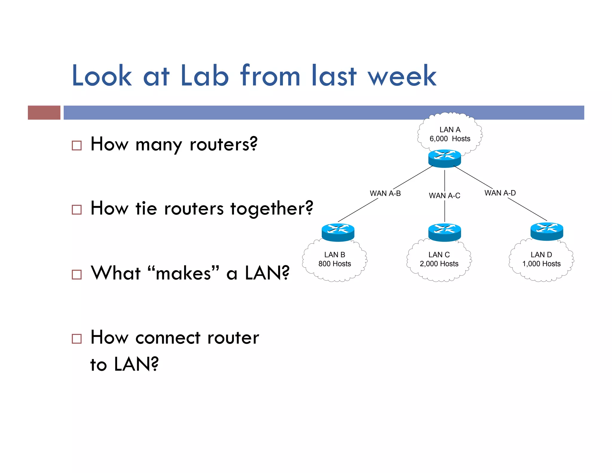
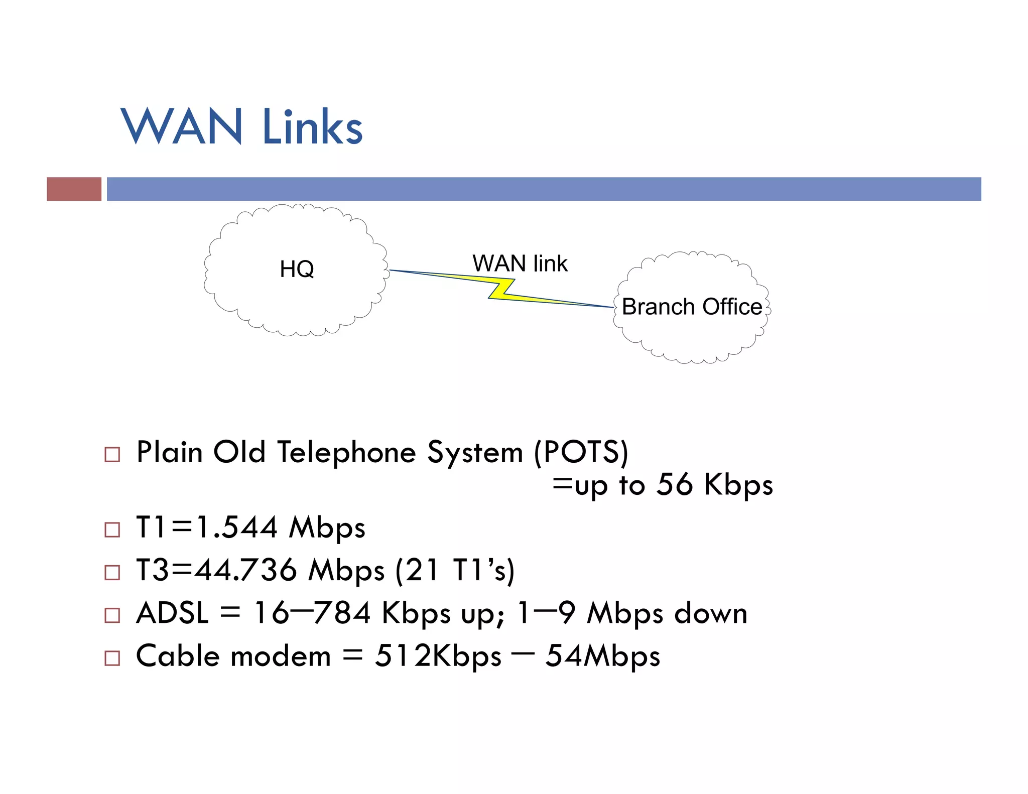
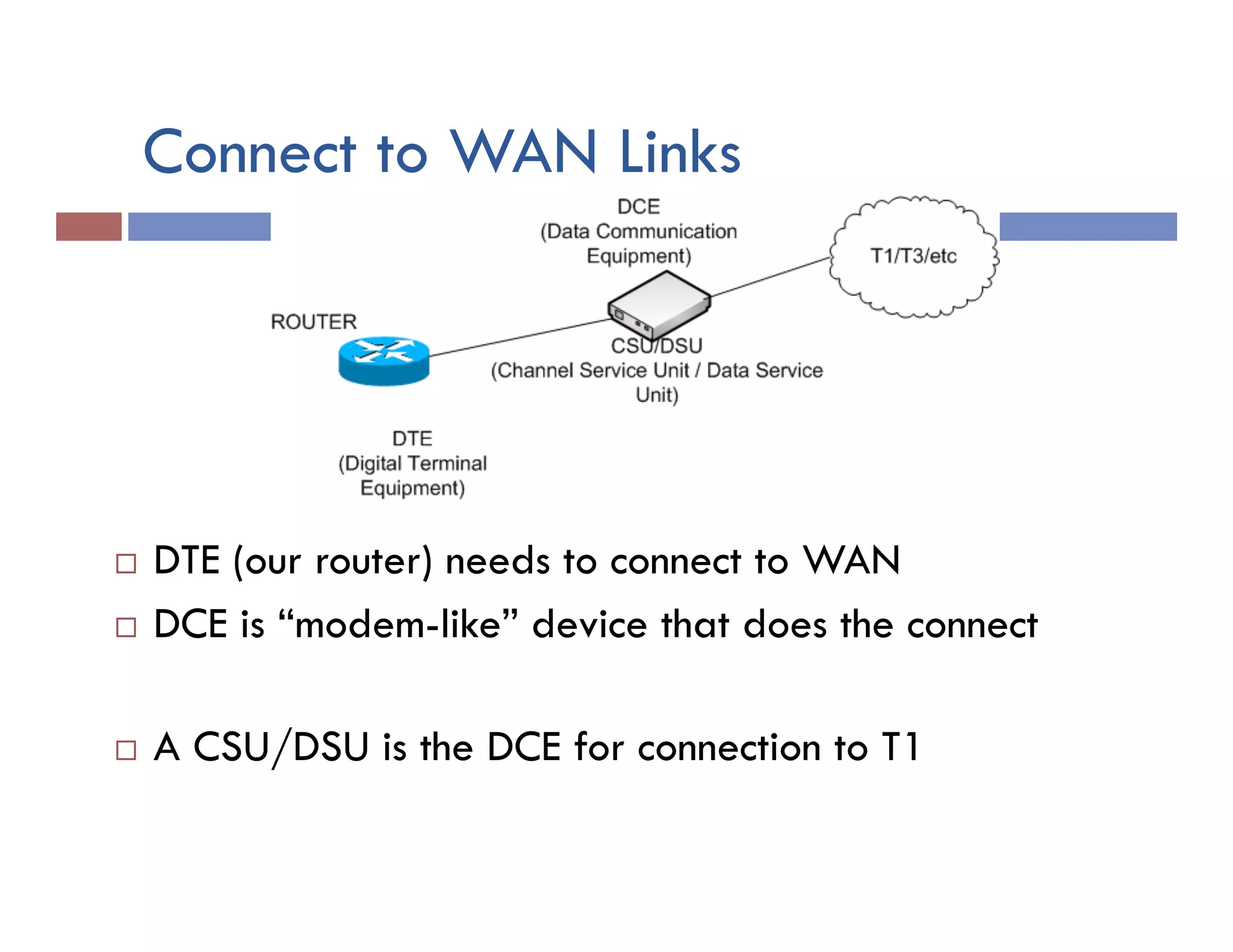
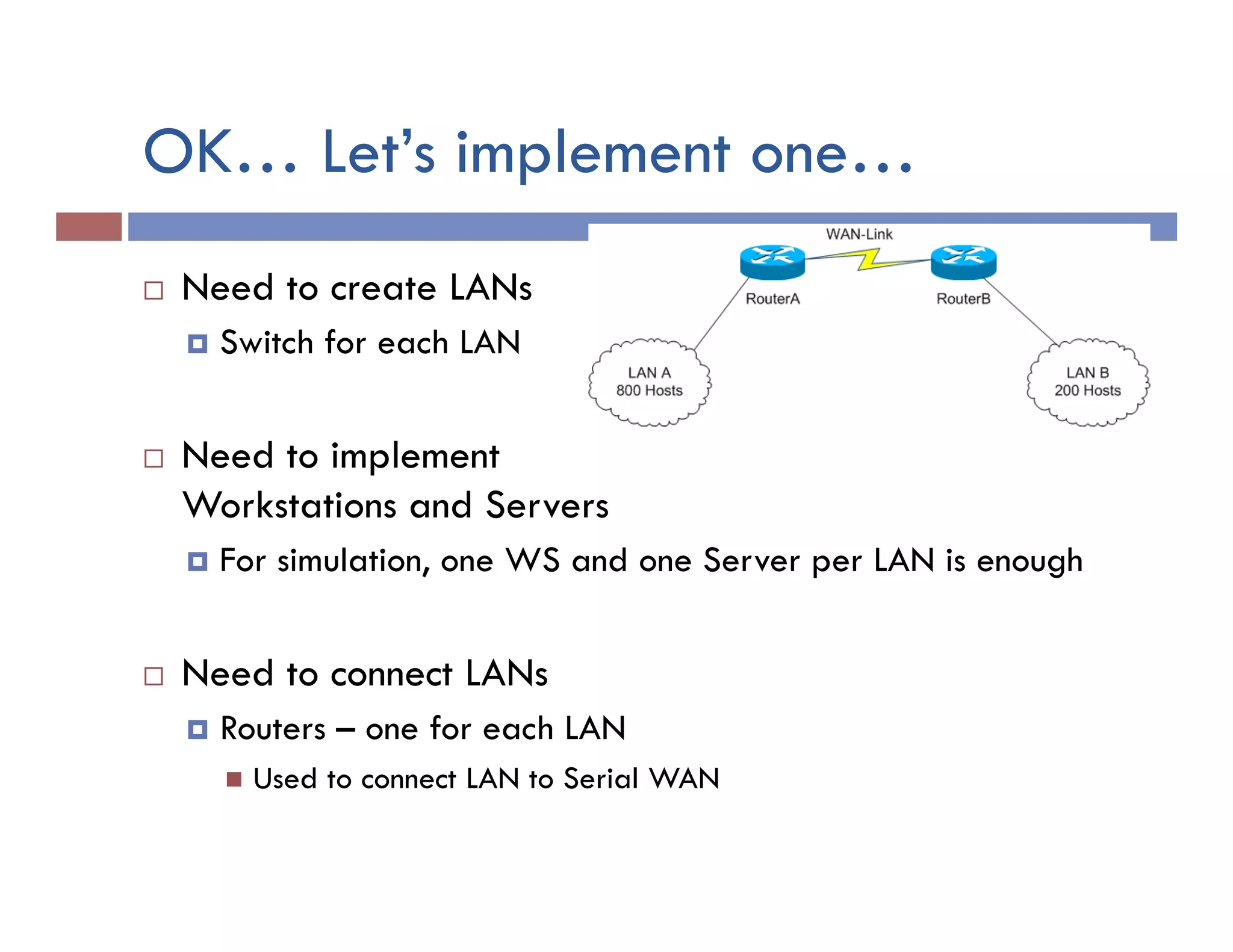
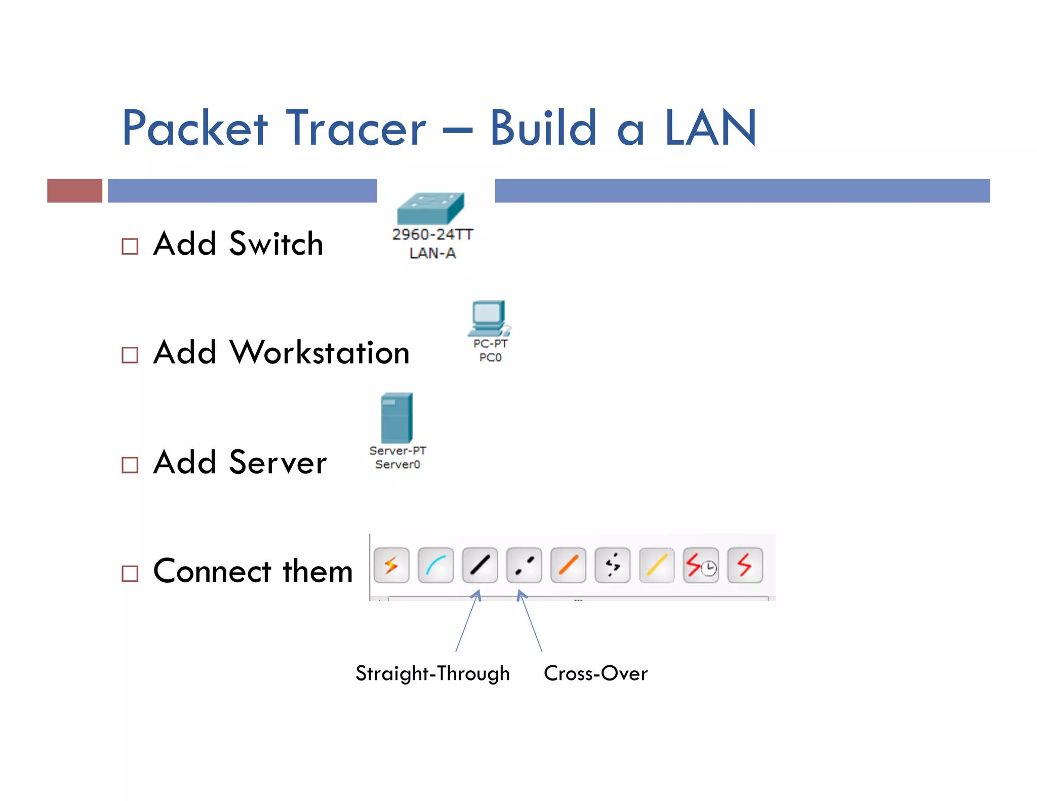
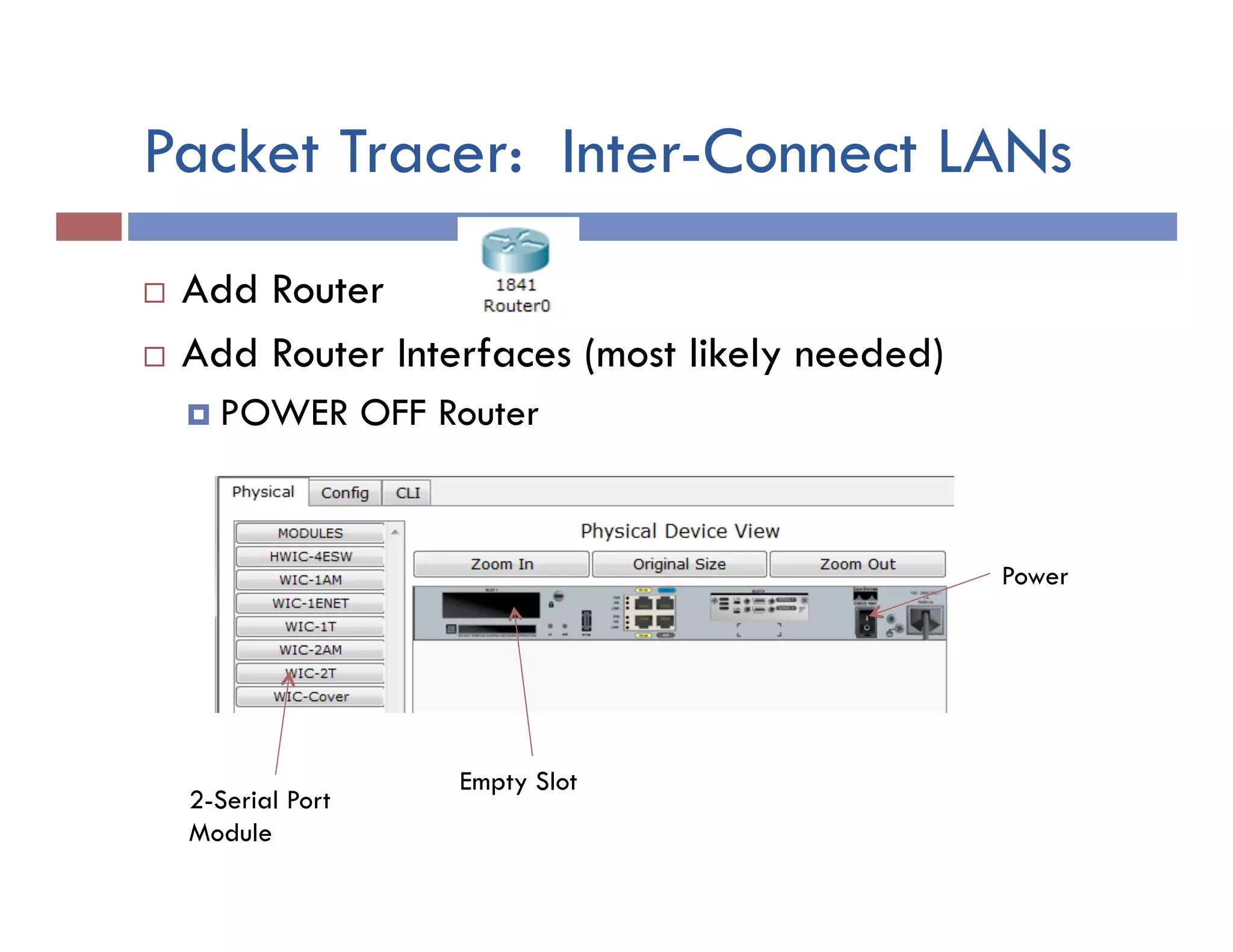

This document provides instructions for designing and implementing a network with Packet Tracer, including: defining the network needs with servers, workstations, switches, and routers; connecting local area networks with routers and wide area network links; configuring IP addresses, subnets, and static routes; and testing connectivity between devices. The network will connect headquarters and a branch office across two locations.