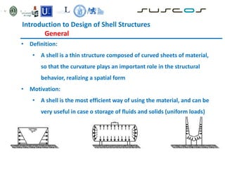
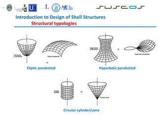
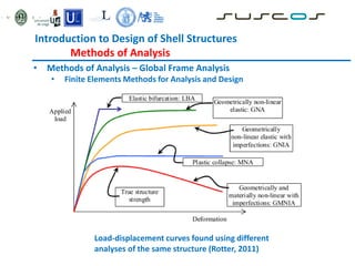
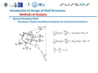
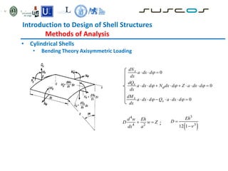
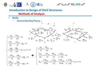
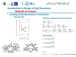
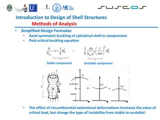
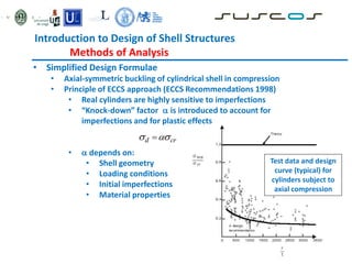
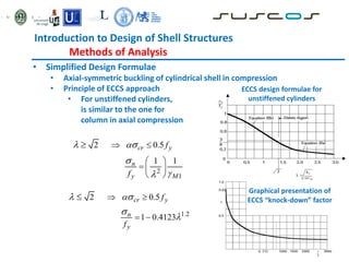
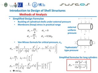
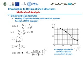
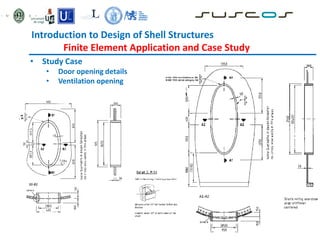
Shell structures are thin curved structures that are efficient at using materials. They can be found in nature and are used for industrial and architectural structures like silos, tanks, and roofs. Shells are difficult to analyze due to their complex behavior under loads. Different types of shells include elliptic paraboloids, hyperbolic paraboloids, and circular cylinders. Buckling is an instability issue for shells where they change shape under load. Several methods are used to analyze shells including finite element analysis, membrane theory, and bending theory equations.


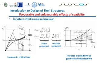
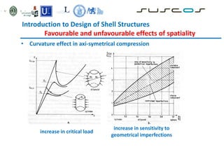
![Introduction to Design of Shell Structures
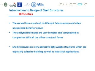
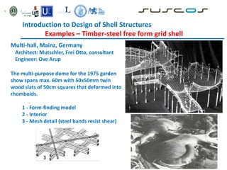
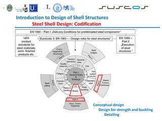
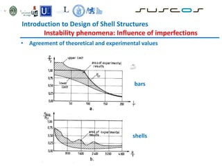
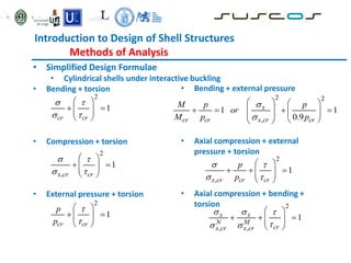
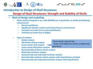
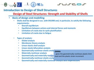
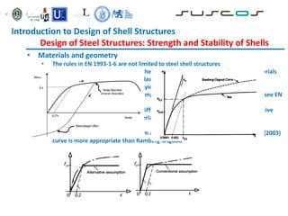
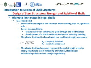
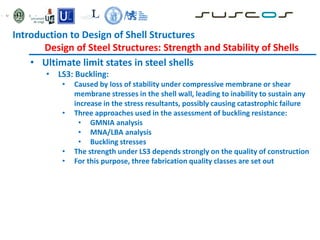
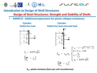
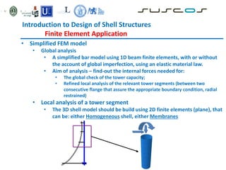
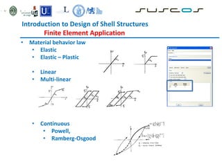
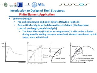
Behavioural phenomenology of shells
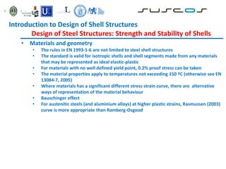
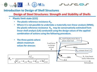
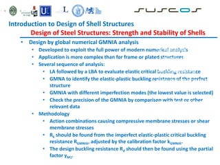
• Behavior of a given structure (slender!) can be controlled by design if
the three characteristic ranges of load-deformation curve are correctly
defined
• Pre-critical range
• Critical point (or range)
• Post-critical range
P
D
Pcr
Critical point
Post-critical
range
Pre-critical range
P(0, Pcr] Structural stability
P > Pcr Structural instability
elastic
Buckling: plastic
dynamic](https://image.slidesharecdn.com/l1617shellstructures-230804033536-216a9f66/85/L16_17_Shell-structures-pdf-20-320.jpg)


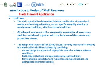
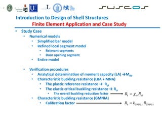
![Introduction to Design of Shell Structures
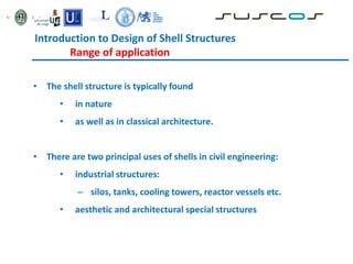
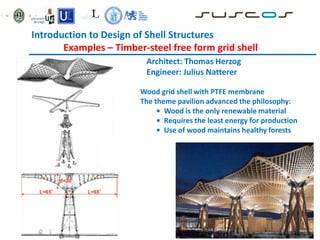
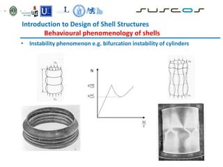
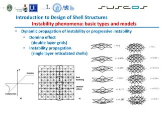
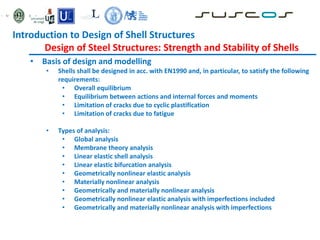
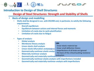
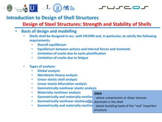
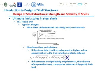
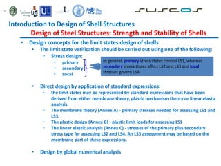
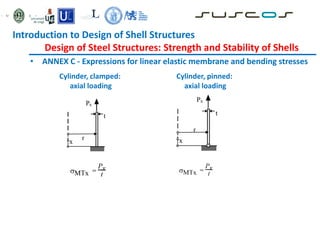
Finite Element Application and Case Study
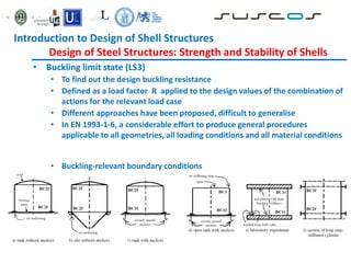
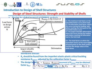
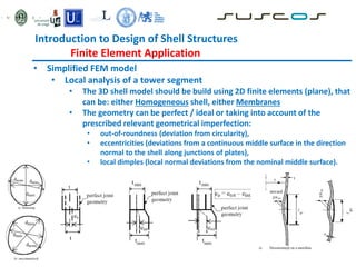
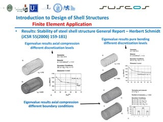
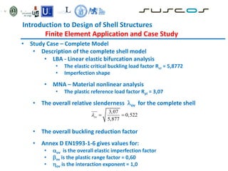
• Study Case – Complete Model
• LA / MNA at reference load results
• Local plastic zones around
connecting flanges
• LBA results Rcr = 5,877
Bottom
section
Axial
force
[kN]
Shear
force
[kN]
Bending
moment
[kNm]
LA 4323 1260 80088
MNA 4323 1260 80088](https://image.slidesharecdn.com/l1617shellstructures-230804033536-216a9f66/85/L16_17_Shell-structures-pdf-122-320.jpg)
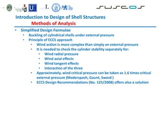
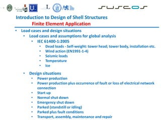
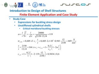
![Introduction to Design of Shell Structures
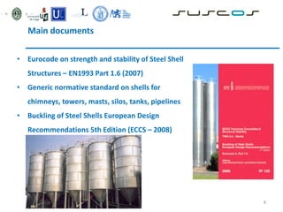
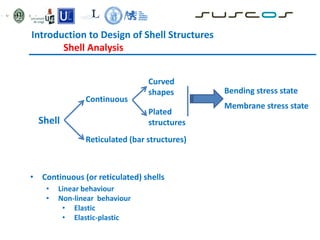
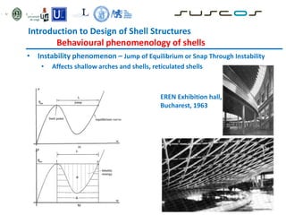
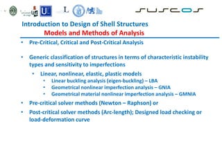
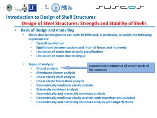
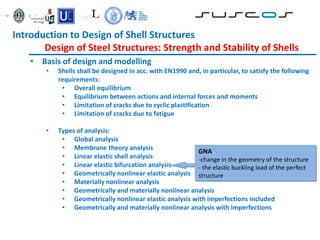
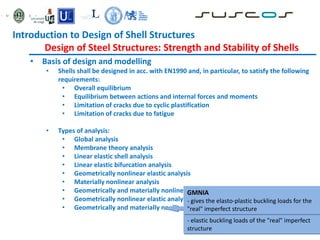
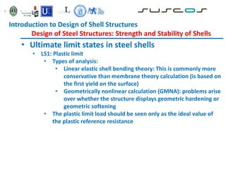
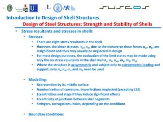
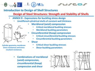
Finite Element Application and Case Study
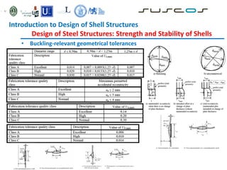
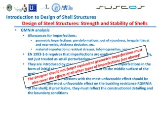
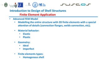
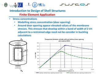
• Study Case – Complete Model
• MNA Rpl = 3,07
• GMNA Rpl = 1,77
• GMNIA Rpl = 1,49
0
0.5
1
1.5
2
2.5
3
3.5
0 1 2 3 4 5 6
Displacement [m]
Load
factor
R
GMNA
MNA
GMNIA
Reactions
at
Axial
force
[kN]
Shear
force
[kN]
Bending
moment
[kNm]
R = 1 4323 1260 80088](https://image.slidesharecdn.com/l1617shellstructures-230804033536-216a9f66/85/L16_17_Shell-structures-pdf-123-320.jpg)
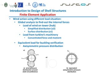
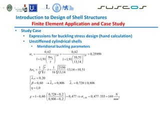
![Introduction to Design of Shell Structures
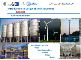
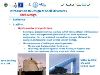
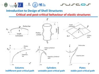
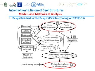
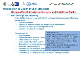
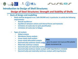
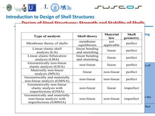
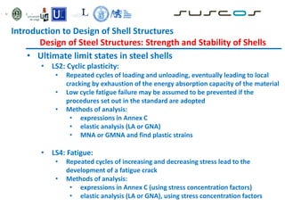
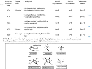
Finite Element Application and Case Study
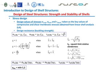
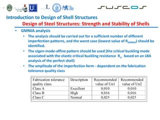
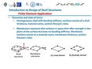
• Study Case – Refined door opening segment
LBA results Rcr = 12.248
• Numerical model
Section
Axial force
[kN]
Shear force
[kN]
Bending moment
[kNm]
Upper section 4413 1231 73988
Bottom section 4413 1231 88514](https://image.slidesharecdn.com/l1617shellstructures-230804033536-216a9f66/85/L16_17_Shell-structures-pdf-125-320.jpg)
![Introduction to Design of Shell Structures
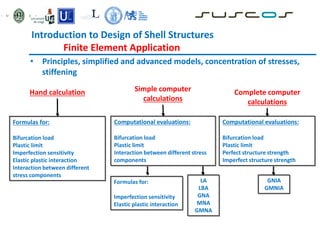
Finite Element Application and Case Study
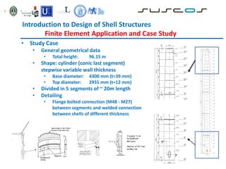
• Study Case – Refined door opening segment
• LA Results
• GMNA Results
Bottom segment
0
0.5
1
1.5
2
2.5
3
0 50 100 150 200 250 300
Displacement [mm]
Load
factor
GMNA](https://image.slidesharecdn.com/l1617shellstructures-230804033536-216a9f66/85/L16_17_Shell-structures-pdf-126-320.jpg)
![Introduction to Design of Shell Structures
Finite Element Application and Case Study
• Study Case – Refined door opening segment
• Numerical model
Section Axial force
[kN]
Shear force
[kN]
Bending moment
[kNm]
Upper section 1586 409 13055
Bottom section 2015 666 23897
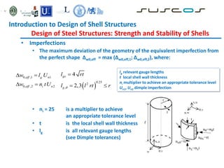
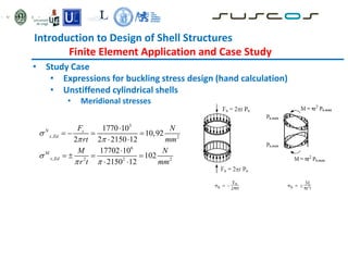
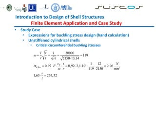
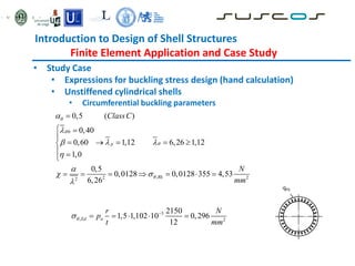
max 2
1 2150
0,46 1 0,1 0,46 1 0,1 0,514
119 13,14
20000
119
2150 13,14
0,541 1430 1,5 1102
w
eq w
c r
k
t
l r l
r t rt
N
q k q
m
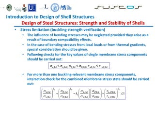
• Transformation of typical wind pressure load distribution
• LA Rpl = (126/355)=2,82](https://image.slidesharecdn.com/l1617shellstructures-230804033536-216a9f66/85/L16_17_Shell-structures-pdf-127-320.jpg)
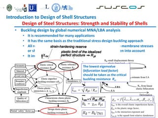
![• Study Case – Refined door opening segment
• LBA Results
Section Rcr
Without EWL 6,8006
With EWL 6,8003
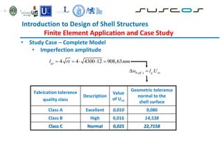
• GMNIA results
• Imperfection afine first buckling mode
• Amplitude of imperfection 23mm and 17mm
corresponding to normal and high tolerance
Quality class kGMNIA
High (~17 mm) 1,79
Normal (~23 mm) 1,72
Relevant segment
0
0.2
0.4
0.6
0.8
1
1.2
1.4
1.6
1.8
2
0 0.002 0.004 0.006 0.008 0.01 0.012 0.014 0.016
Rotation [rad]
Load
factor
GMNIA normal
GMNIA high
kGMNIA
Introduction to Design of Shell Structures
Finite Element Application and Case Study](https://image.slidesharecdn.com/l1617shellstructures-230804033536-216a9f66/85/L16_17_Shell-structures-pdf-128-320.jpg)


