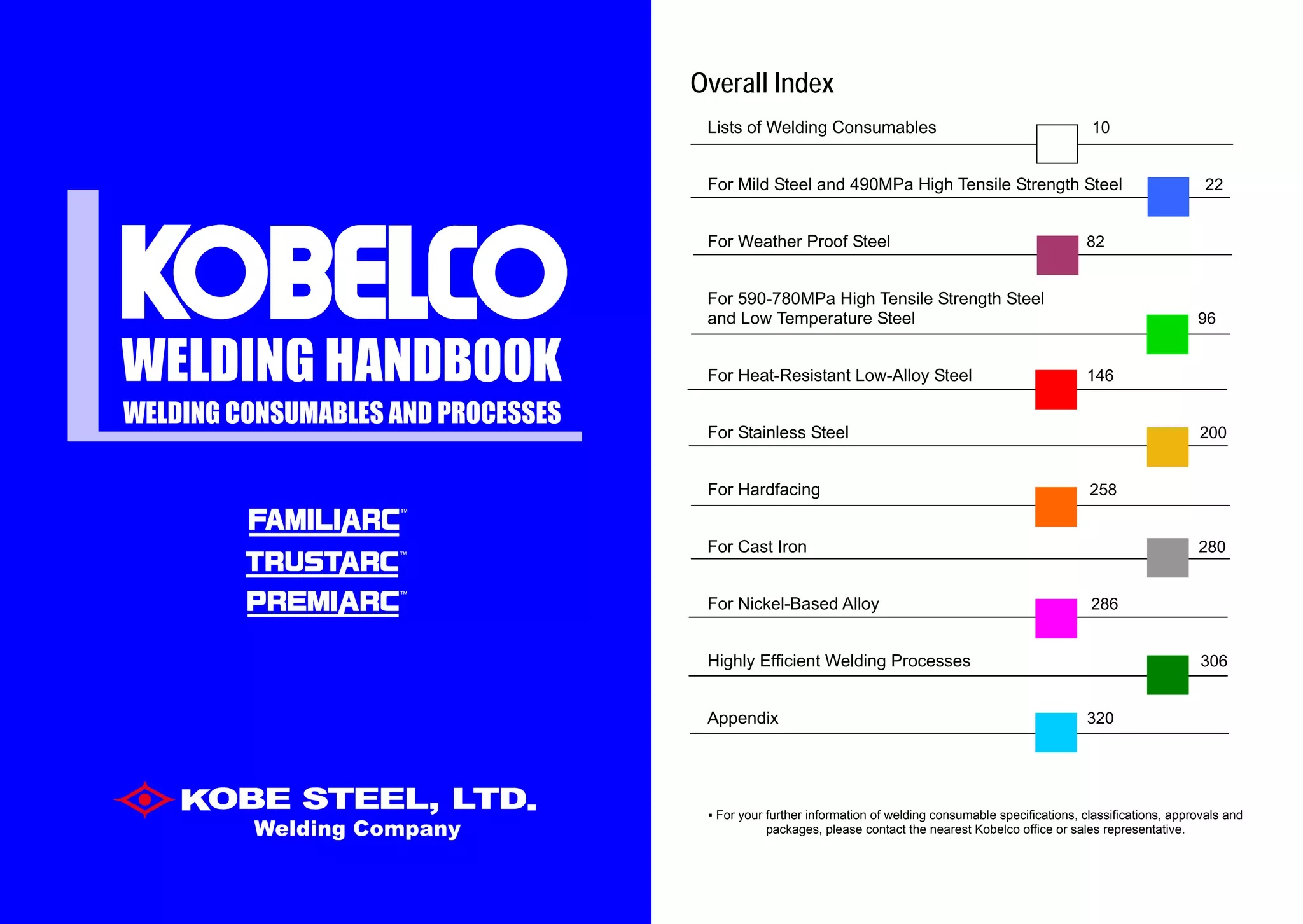
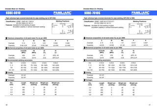
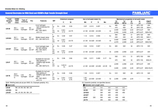
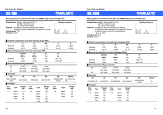
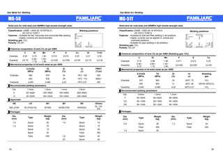
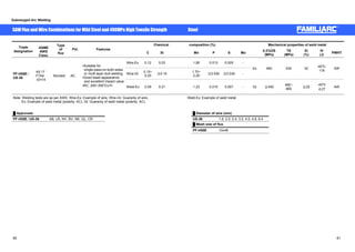
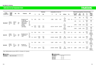
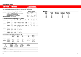
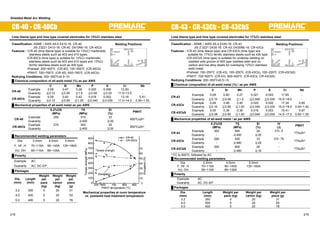
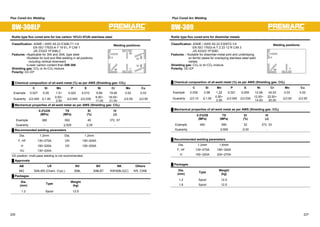
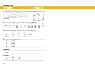
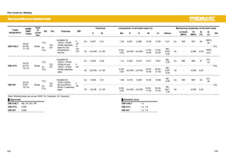
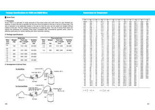
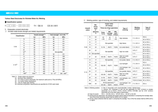
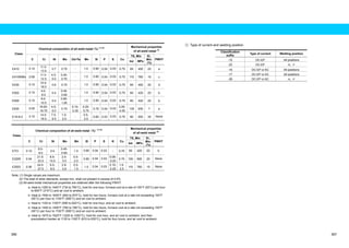
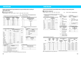
This document provides a list of welding consumables for various welding processes and materials. It includes 108 products grouped by:
- Mild steel and 490MPa high tensile steel (22 products)
- Flux-cored arc welding (3 products for mild steel)
Each product listing includes the trade designation, ASME/AWS classification, JIS standard, filler metal number, and applicable page number for more details. A clickable index is provided for navigating to product pages.

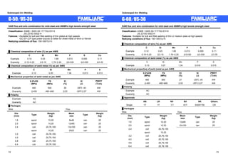
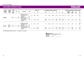
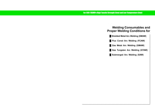

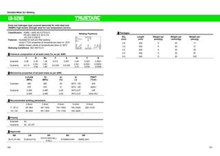
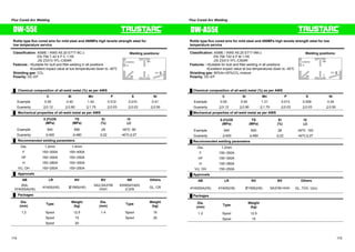
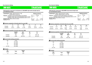
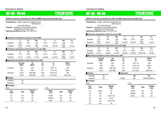
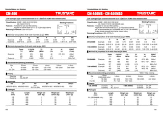
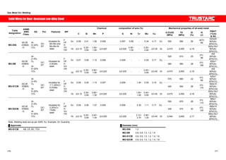
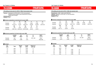
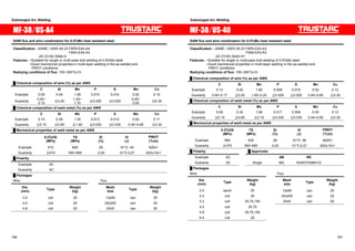
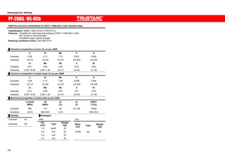
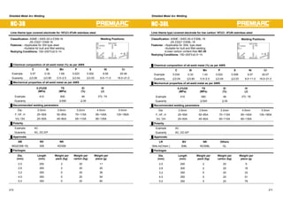

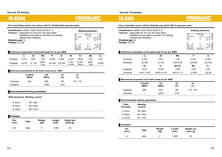
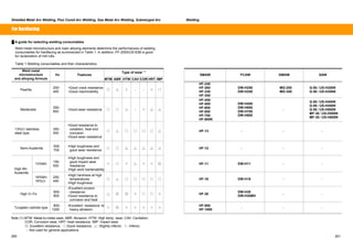
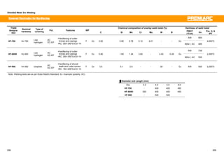
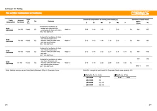
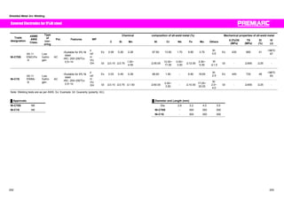

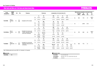
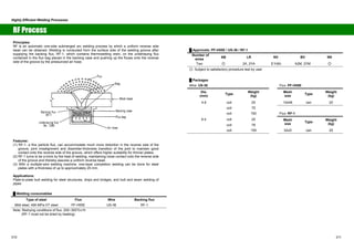

Y46 class
steel ҈460 570-720
҈20
3Y46
4Y46
5Y46
㧙20
㧙40
㧙60
҈47
Y50 class
steel ҈500 610-770
3Y50
4Y50
5Y50
㧙20
㧙40
㧙60
҈50
Y55 class
steel ҈550 670-830
3Y55
4Y55
5Y55
㧙20
㧙40
㧙60
҈55
Y62 class
steel ҈620 720-890
҈18
3Y62
4Y62
5Y62
㧙20
㧙40
㧙60
҈62
Y69 class
steel ҈690 770-940 ҈17
3Y69
4Y69
5Y69
㧙20
㧙40
㧙60
҈69
LR ҈375 ҈460 (҈490) 1.5Ni
҈22
BV ҈355 ҈470 (҈490)
N15
㧙80
LR ҈375 ҈420 (҈450) ҈25 3.5Ni
BV ҈355 ҈470 (҈490) ҈22 N35
㧙100
LR ҈375 ҈500 (҈540) ҈25 5Ni
BV ҈380 ҈520 (҈540) ҈22 N50
㧙120
LR ҈375 ҈600 (҈640) ҈25 9Ni
LR
BV
Low
temperature
steel
BV ҈480 ҈670 (҈690) ҈22 N90
㧙196
҈34 (҈27)
Y42 class
steel ҈420 530-680
3Y42/IIIY42
4Y42/IVY42
5Y42/VY42
㧙20
㧙40
㧙60
Y46 class
steel ҈460 570-720
҈20
3Y46/IIIY46
4Y46/IVY46
5Y46/VY46
㧙20
㧙40
㧙60
҈47
Y50 class
steel ҈500 610-770
3Y50/IIIY50
4Y50/IVY50
5Y50/VY50
㧙20
㧙40
㧙60
҈50
Y55 class
steel ҈550 670-830
3Y55/IIIY55
4Y55/IVY55
5Y55/VY55
㧙20
㧙40
㧙60
҈55
Y62 class
steel ҈620 720-890
҈18
3Y62/IIIY62
4Y62/IVY62
5Y62/VY62
㧙20
㧙40
㧙60
҈62
Y69 class
steel ҈690 770-940 ҈17
3Y69/IIIY69
4Y69/IVY69
5Y69/VY69
㧙20
㧙40
㧙60
҈69
㧙55 ҈41 ҈305 400-560 (҈400) 5/V NV2-4
NV2-4L 㧙60 ҈34
҈22
㧙55 ҈41 ҈375 490-660 (҈490)
5Y/VY NV4-4
NV4-4L 㧙60 ҈34
҈275 ҈420
҈345 ҈440
҈390 ҈570
Low
temperature
steel(4)
҈490 ҈640
҈25
NV1.5Ni
NV3.5Ni
NV5Ni
NV9Ni
㧙95
㧙115
㧙145
㧙196
҈34
҈440
҈470
NV
Heat
resistant
steel
҈305
҈480
҈18
NV0.3Mo
NV1Cr0.5Mo
NV2.25Cr1Mo
㪄 㪄
Note: (1) Tensile strengths and impact values in parentheses are requirements in butt welding.
(2) Impact value in bracket is requirement in automatic 2-layer welding.
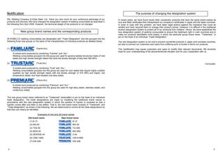
326 327](https://image.slidesharecdn.com/kobelcoweldinghandbook2008ok-141107002434-conversion-gate01/85/Kobelco-welding-handbook-2008ok-164-320.jpg)
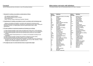
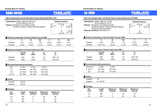
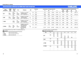
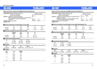
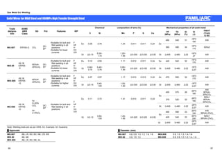
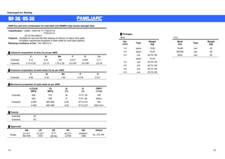
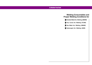
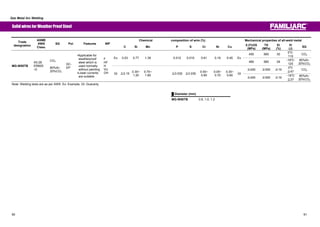
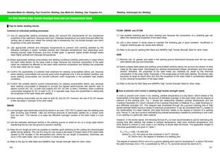
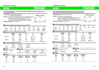
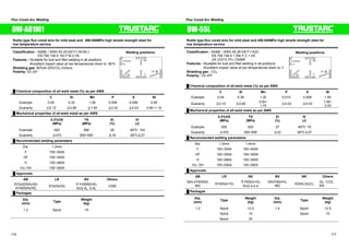
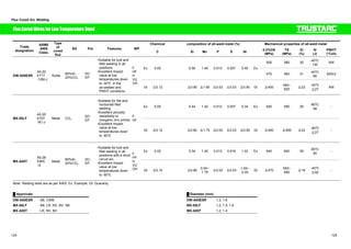
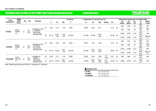
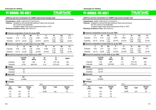
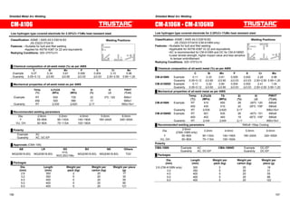
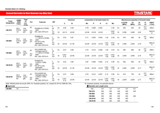
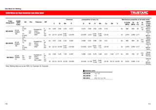
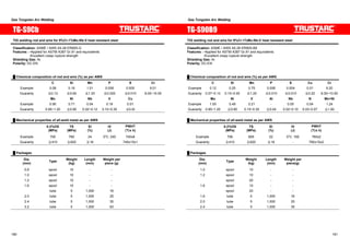
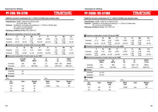
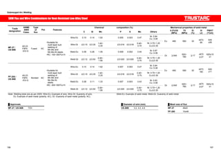
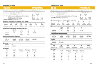
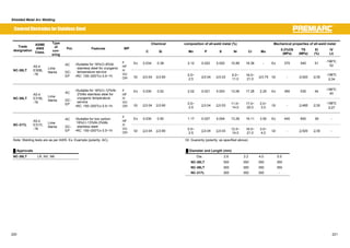
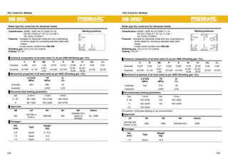
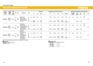
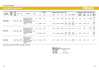
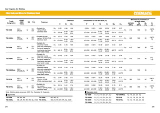
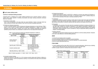
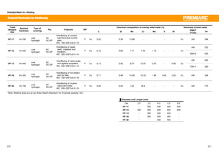
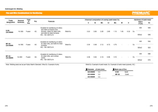
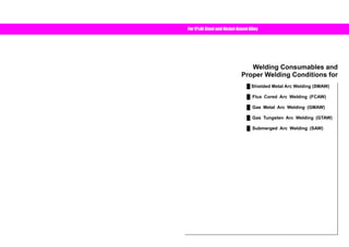
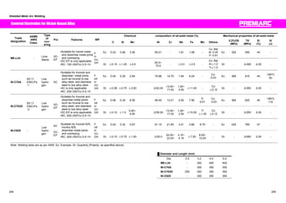
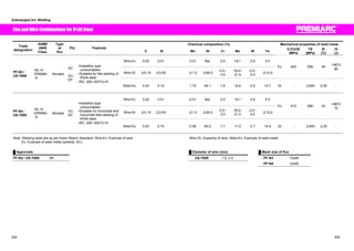
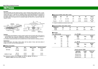
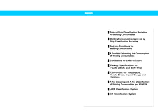
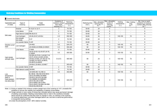
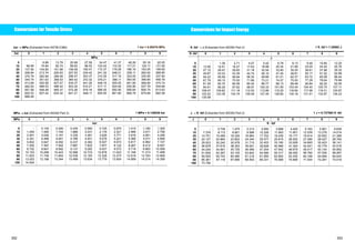
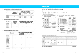
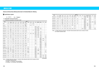
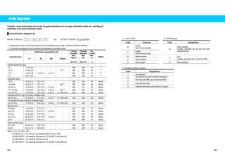
![Welding Consumables Approved by Ship Classification Societies
Notes on usage
The ship classification approvals of welding consumables shown below are those renewed as of
December 25, 2007. They may be cancelled, added, or changed and may not necessarily be applied to
all the welding consumables produced at the production plants (Ibaraki Plant, Saijo Plant, Fukuchiyama
Branch, and Fujisawa Branch) of Kobe Steel. Therefore, please contact with the International
Operations Dept. of the Welding Company of Kobe Steel when you need the ship classification approval
of a particular welding consumable to be used. These tables abbreviate the names of ship classification
societies and some designations to those noted in the following. As regards “Grade,” refer to the rules of
ship classification societies for welding consumables, which are listed at page 322.
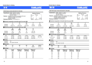
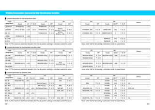
Ű Covered electrodes for mild steel and high tensile strength steel
[Ship classification societies]
AB: American Bureau of Shipping LR: Lloyd’s Register of Shipping NV: Det Norske Veritas
BV: Bureau Veritas NK: Nippon Kaiji Kyokai CR: Central Research of Ships S. A.
GL: Germanischer Lloyd KR: Korean Register of Shipping CCS: China Classification Society
[Welding positions]
F: Flat position V: Vertical position VD: Vertical down O: Overhead; H: Horizontal
[Other abbreviations]
MG: Maker guarantee MED: Maximum electrode diameter
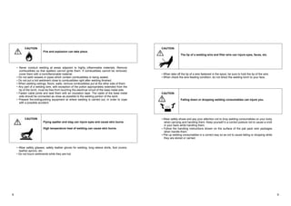
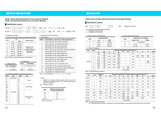
Trade AB LR NV BV NK
designation Grade AP F HF Grade WP Grade WP Grade WP Grade MED(1) F HF
Others
B-14 3 ҇5.0 ҇8.0 3m F, V, O 3 F, V, O 3 F, V, O KMW3 5(8) F, V, O CR, GL
B-17 3 ҇5.0 ҇8.0 3m F, V, O 3 F, V, O 3 F, V, O KMW3 5(8) F, V, O CR, GL
RB-26 2 ҇5.0 - 2m F, V, O - - - - KMW2 5 F, V, O
LB-26 3H15 ҇5.0 ҇8.0 3m, 3Ym(H15) F, V, O 3YH10 F, V, O 3, 3YH F, V, O KMW3H15 5(8) F, V, O CR
LB-52 3H10,3Y,3Y400 ҇5.0 ҇6.0 3m, 3Ym(H15) F, V, O 3YH10 F, V, O 3, 3Y F, V, O KMW53H10 5(8) F, V, O
LB-52A - - - - - - - - - KMW53HH 5(6) F, V, O
LB-52U 3H10, 3Y ҇5.0 - 3m, 3Ym(H15) F, V, O 3YH10 F, V, O 3, 3YHH F, V, O KMW53H10 5 F, V, O CCS
LB-52T 3H10, 3Y ҇5.0 - 3m, 3Ym(H15) F, V, O 3YH10 F, V, O 3, 3YHH F, V, O KMW53H10 5 F, V, O CR
LB-52-18 3H10, 3Y ҇4.0 ҇6.0 3m, 3Ym(H15) F, V, O 3YH10 F, V, O - - KMW53HH 4(6) F, V, O
LB-62 3YQ500(H10) ҇4.0 ҇6.0 3m, 3Ym(H15) F, V, O 3YH10 F, V, O 3, 3YHH F, V, O KMW3Y50H10 5(6) F, V, O CR
LB-62UL - - - - - - - - - - - - CCS
LB-80UL - - - - - - - - - KMW3Y69H5 4(5) F, V, O CCS
LB-88LT - - - - - 5Y69H5 F, V, O - - - - -
LB-106 MG(E10016-G) ҇6.0 - - - - - - - KMW3Y62H5 5(6) F, V, O CR
LB-116 MG(E11016-G) ҇4.0 ҇6.0 - - 4Y69H5 F, V, O - - MG(E11016-G) 4(5) F, V, O
LT-B50 3, 3Y* - ҇8.0 3m, 3Ym, 3YG F 3, MG F 3, 3Y F KMW53 8 F, H CR, GL
LT-B52A 3H10, 3Y ҇4.5 ҇8.0 3G, 3YG(H15) F, V, O 3YH15 F, V, O 3, 3YHH F, V, O KMW53H 4.5(8) F, V, O
Z-27 3 - ҇8.0 3m, 3G F 3 F 3 F KMW3 8 F CR
Z-43F 3 - ҇8.0 3m, 3G F - - - - KMW3 8 F
Z-44 3 ҇6.0 - 3m F, V, O 3 F, V, O - - KMW3 5 F, V, O
Note: (1) The maximum electrode diameter (mm) for all-position welding is indicated outside the paren- thesis while that for flat welding is indicated inside the parenthesis.
328 329](https://image.slidesharecdn.com/kobelcoweldinghandbook2008ok-141107002434-conversion-gate01/85/Kobelco-welding-handbook-2008ok-165-320.jpg)
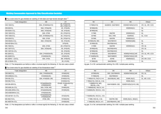
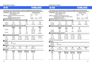
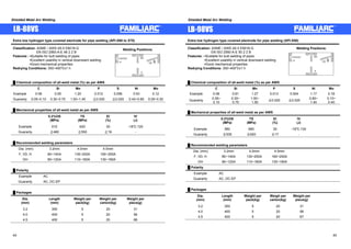
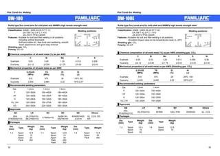
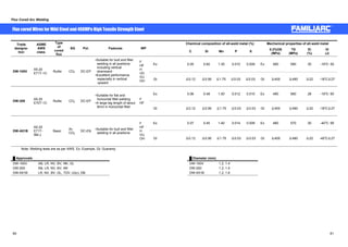
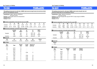
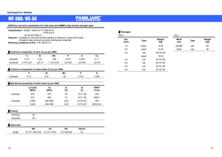
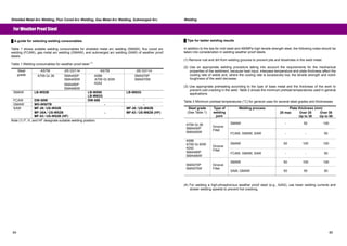
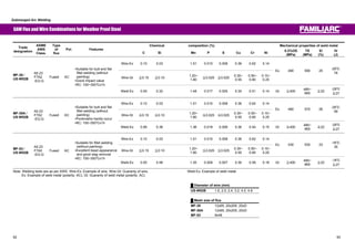
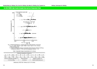
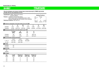
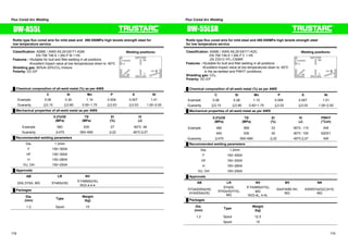
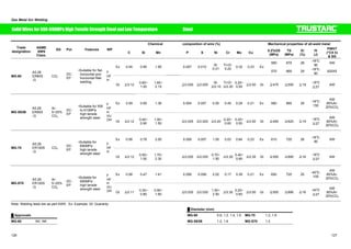
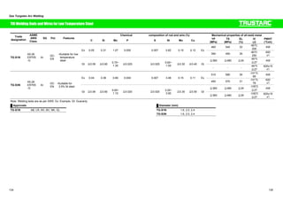
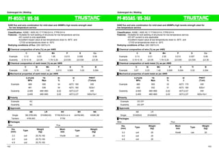
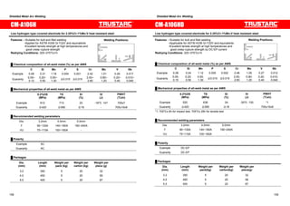
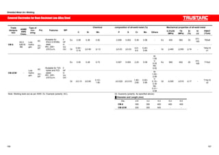
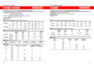
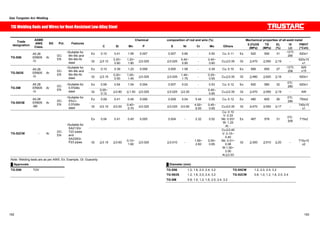
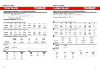
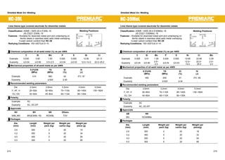
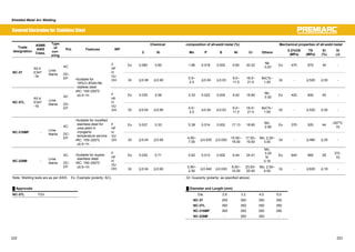
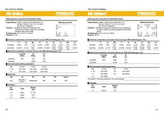
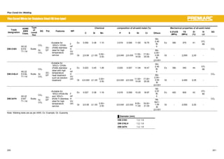
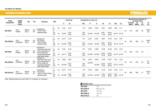
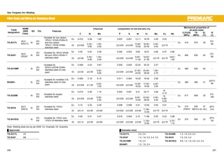
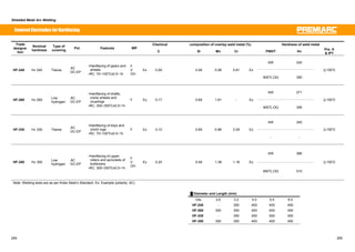
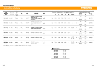
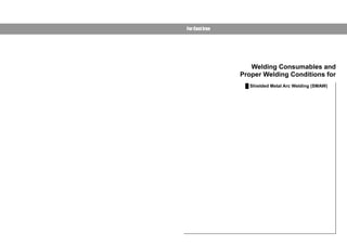
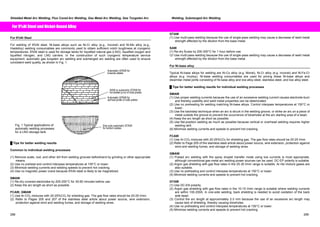
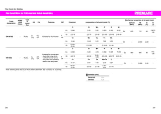
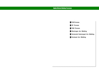
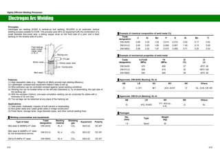
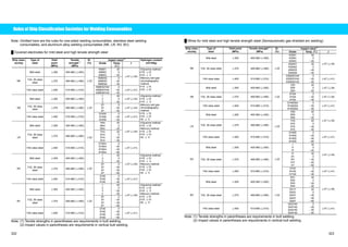
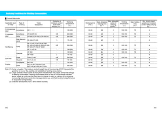
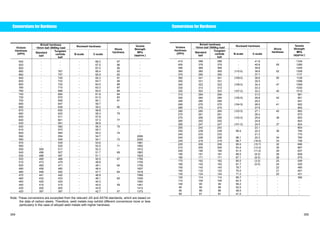
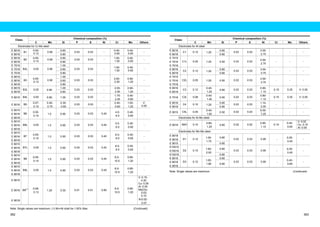
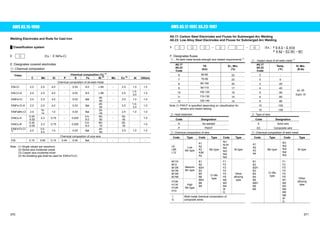
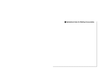
![Welding Consumables Approved by Ship Classification Societies
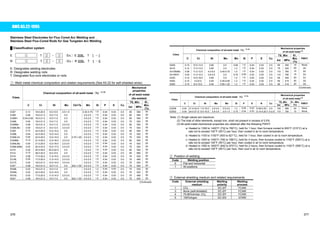
Ű Flux/wire combinations for submerged arc welding [Multi-pass and double-sided two pass welding] (1)
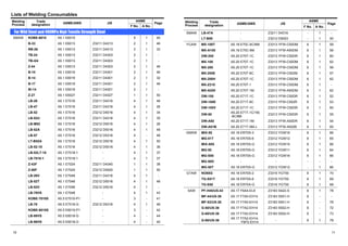
Trade designation AB LR NV BV NK Others
US-36/G-60 1T 1T IT A1T KAW1TM CR
US-36/G-80 2M 2M ΥYM A3M KAW2M KR
US-36/MF-38 2T, 2YT, 3M, 3YM 2T, 2YT, 3YM ΤYT, ΥYM A2, 2YT, 3, 3YM KAW52T, 53M CR, GL, KR
US-36/MF-53 2T, 2YT 2M, 2YM ΥY - KAW52
US-36(˜2)/MF-53 ٤ - - - ٤
US-36/MF-300 2T, 2YT, 3M, 3YM 2T, 2YT, 3YM ΤYT, ΥYM - - GL
US-36/PF-H55E 3TM, 3YTM, 3Y400TM 3T, 3YM, 3YT ΥYTM A3YTM KAW53Y40TM CR, GL
US-36(˜2)/PF-H55E ٤ 3T, 3YM, 3YT - A3, A3YT ٤ GL
US-36/PF-H55LT 3M, 3YM, MG 5Y40M(H5) ΧYM, NV2-4, 4-4 A4YM, MG KAWL3M
US-36(˜2)/PF-H55LT 4YM, MG - ΧYM - -
US-40/MF-38 MG - - - KAW3Y50MH10
US-43/PF-H45 3TM 3M, 3T ΥTM A3TM KAW3TM CR, GL
US-43(˜2)/PF-H45 ٤ 3M, 3T - - ٤
US-43/PF-I50 3TM, 3YTM 3T, 3YM, 3YT - - KAW53TM
US-49/MF-38 3YTM 3T, 3YM, 3YT ΥYTM A3YTM KAW3Y46TMH10 CCS
US-36J/PF-H55AS 5Y400(H5) 5Y40MH5 - - -
US-80LT/PF-H80AS 4YQ690 - - - -
US-80LT/PF-H80AK - - ΧY69M - -
US-709S/PF-N4 - - - - KAWL92M
Note: (1) The designators put after a numeral signify the following: T: Double-sided two pass welding M: Multi-pass welding.
338 339](https://image.slidesharecdn.com/kobelcoweldinghandbook2008ok-141107002434-conversion-gate01/85/Kobelco-welding-handbook-2008ok-170-320.jpg)
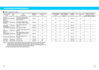
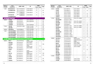
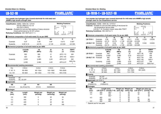
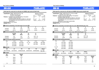
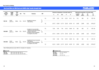
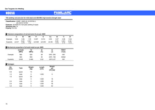
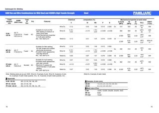
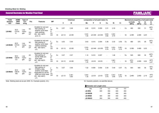
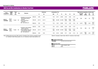
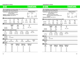
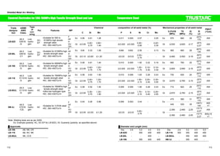
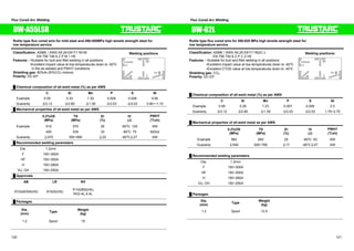
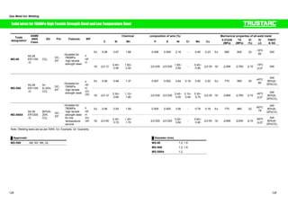
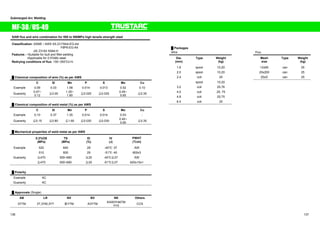
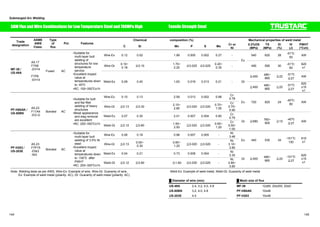
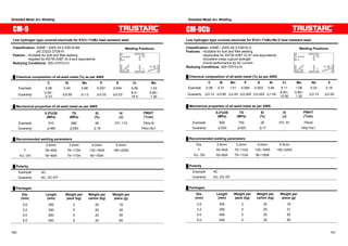
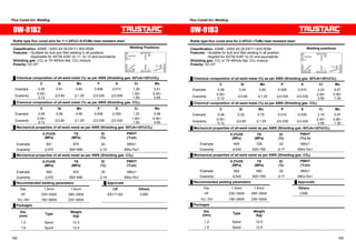
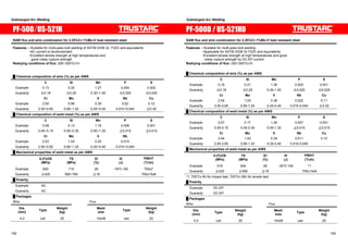
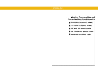
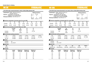
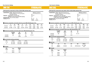
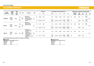
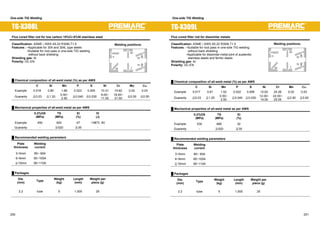
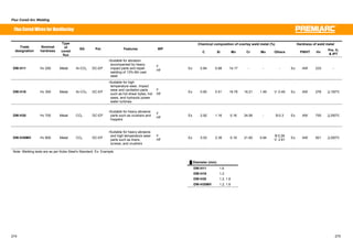
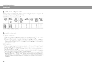
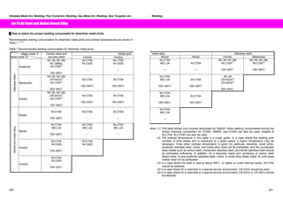
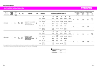
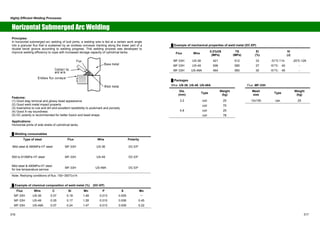
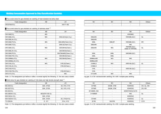
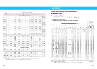
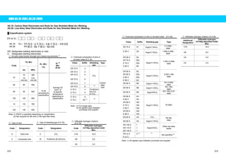
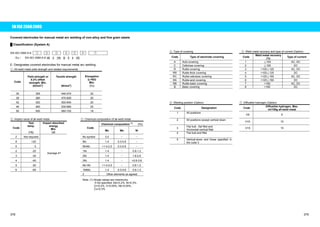
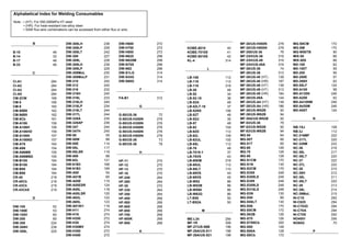
![A Guide to Estimating the Consumption of Welding Consumables
Figure 1 shows the calculated consumption of welding consumables as a function of plate thickness,
welding process, groove angle, and root opening for butt joints. Figure 2 shows the calculated
consumption of welding consumables as a function of fillet size, welding process, and reinforcement size.
These diagrams were developed using the calculations obtained by the following equation for both
groove and fillet welding joints under the prerequisites given below.
C = [(A1 + A2) × L × G㧛E ] × 1㧛10
where C: Consumption of welding consumables (kg); A1: Area of Section A1 weld metal (mm2) (See Fig.
3); A2: Area of Section A2 reinforcement (mm2) (See Fig. 3); L: Weld length (m); G: Specific gravity of
weld metal (7.85 g/cm3); E: Deposition Efficiency (%) — SMAW covered electrodes: 55%; GMAW
solid/metal-cored wires: 95%; FCAW flux-cored wires: 90%; SAW solid wires: 100%.
Fig. 1 Consumption of covered electrodes in SMAW and solid/metal-cored
wires in GMAW of butt joints
Fig. 2 Consumption of covered electrodes in SMAW, flux-cored wires in FCAW,
solid/metal-cored wires in GMAW, and solid wires in SAW of fillet joints
Butt weld joint
H = (2 / 46.8) x T + 0.86
Fillet weld joint
(A2 is given in ratio in Fig. 3)
Fig. 3 Weld sizes (Ĭ in deg., H, R, S, and T in mm)
346 347](https://image.slidesharecdn.com/kobelcoweldinghandbook2008ok-141107002434-conversion-gate01/85/Kobelco-welding-handbook-2008ok-174-320.jpg)


![Types%20of%20 Welding[1]](https://cdn.slidesharecdn.com/ss_thumbnails/types20of20welding1-091203225849-phpapp02-thumbnail.jpg?width=640&height=640&fit=bounds)


![arc_welding_safety[1]](https://cdn.slidesharecdn.com/ss_thumbnails/5ec67737-dec9-46f8-8fd9-fb83767a83f8-150902111301-lva1-app6891-thumbnail.jpg?width=640&height=640&fit=bounds)
