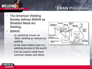
1. SMAW, also known as stick welding, is the most widely used arc welding process that uses a consumable electrode coated in flux.
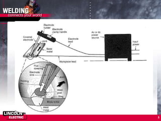
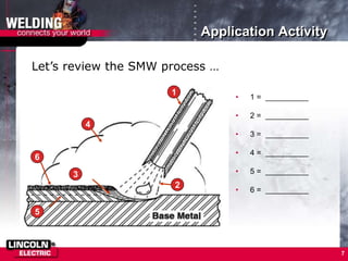
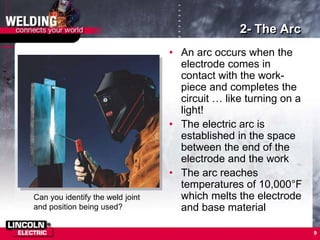
2. The SMAW process involves an electric arc formed between the electrode and workpiece that reaches temperatures over 10,000°F, melting the electrode and workpiece to form a weld puddle. The flux coating produces shielding gas and slag.
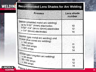
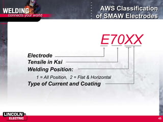
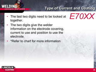
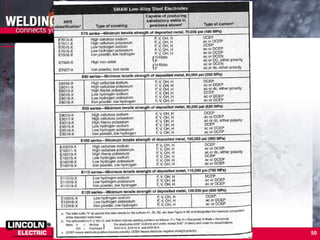
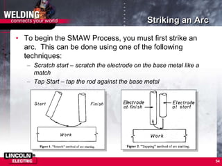
3. SMAW electrodes are identified by diameter and a classification system involving letters and numbers indicating metal alloy, intended use, and other properties like tensile strength and recommended welding positions.