Downloaded 47 times

![Non-trivial AR Painting with Light [Bandyopadhyay, Raskar, Fuchs 2001]](https://image.slidesharecdn.com/svrraskar-090428161336-phpapp01/75/Svr-Raskar-5-2048.jpg)


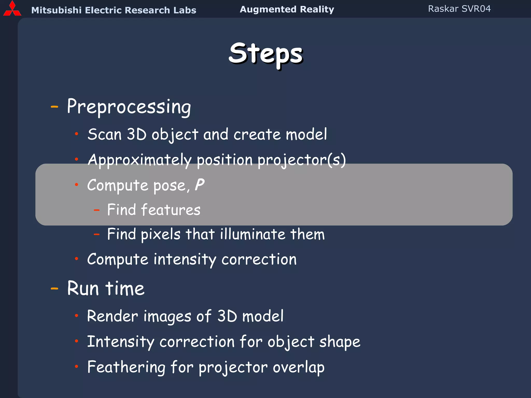
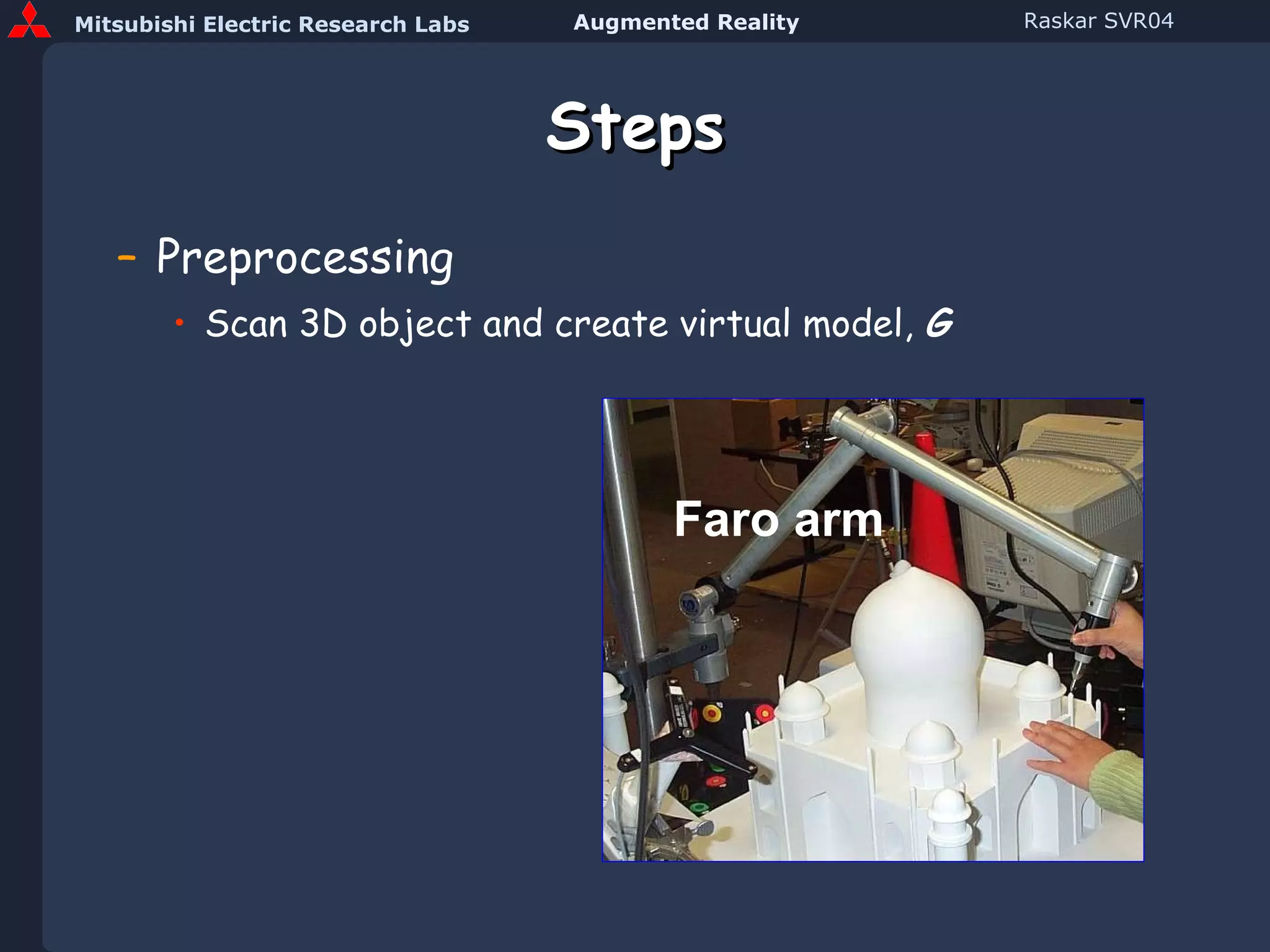
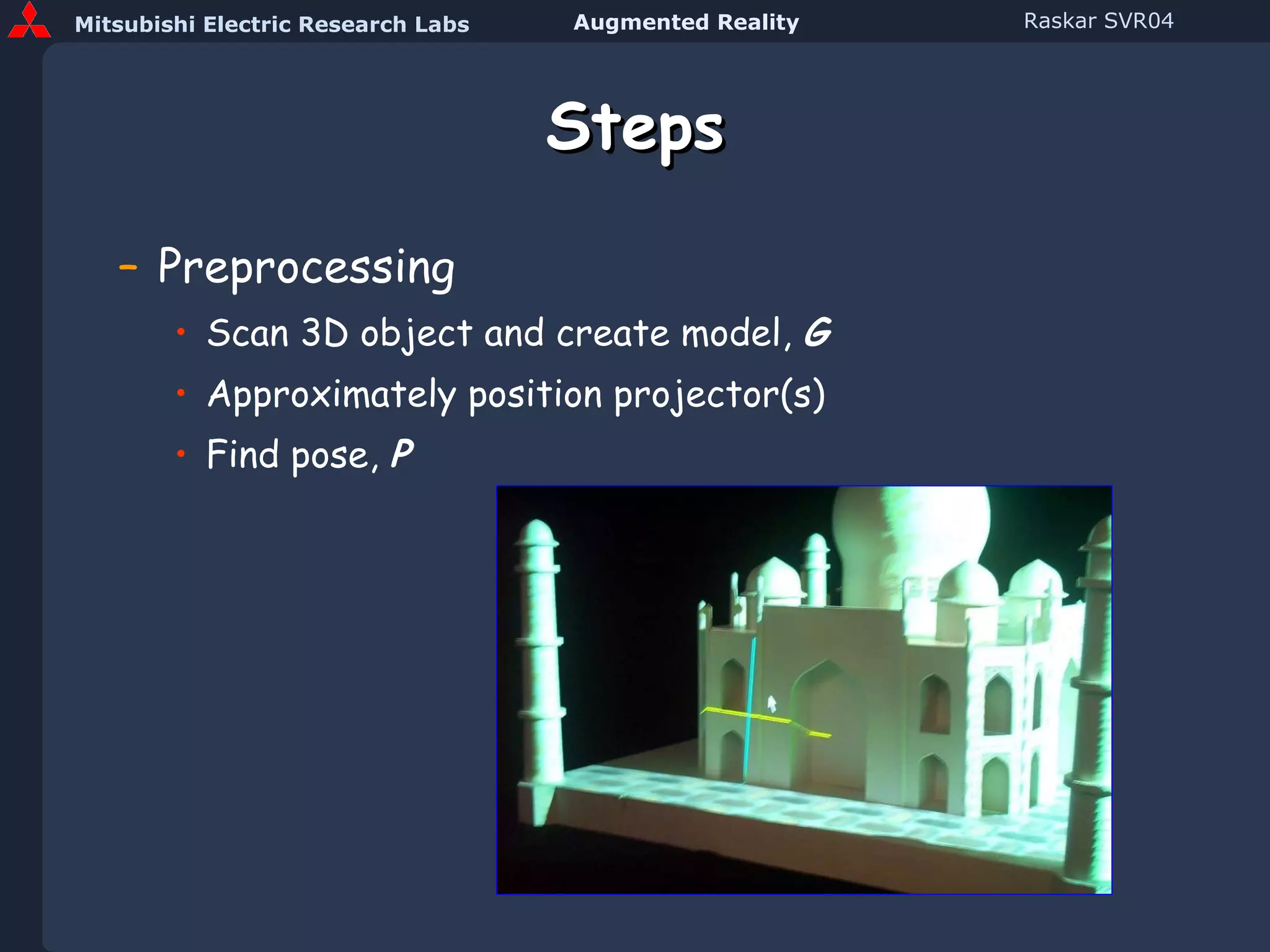
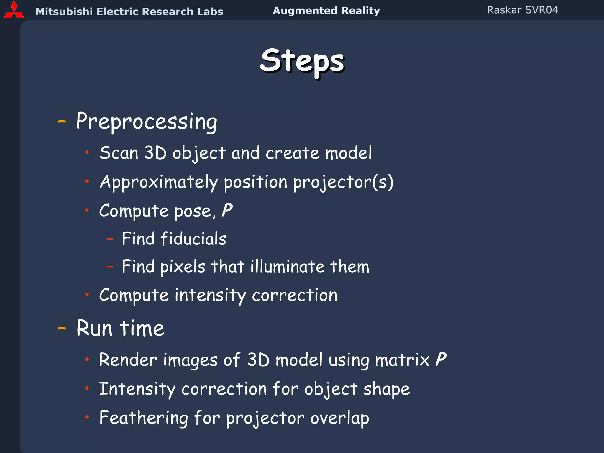

![Steps Preprocessing Scan 3D object and create model, G Approximately position projector(s) Compute pose, P Compute intensity correction, Run time Render image [ I ] using model G from pose P](https://image.slidesharecdn.com/svrraskar-090428161336-phpapp01/75/Svr-Raskar-44-2048.jpg)
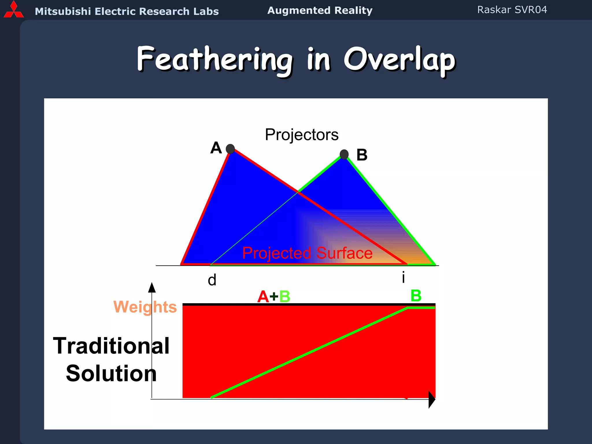
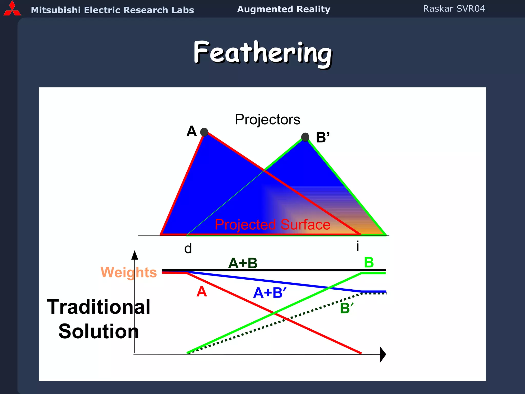
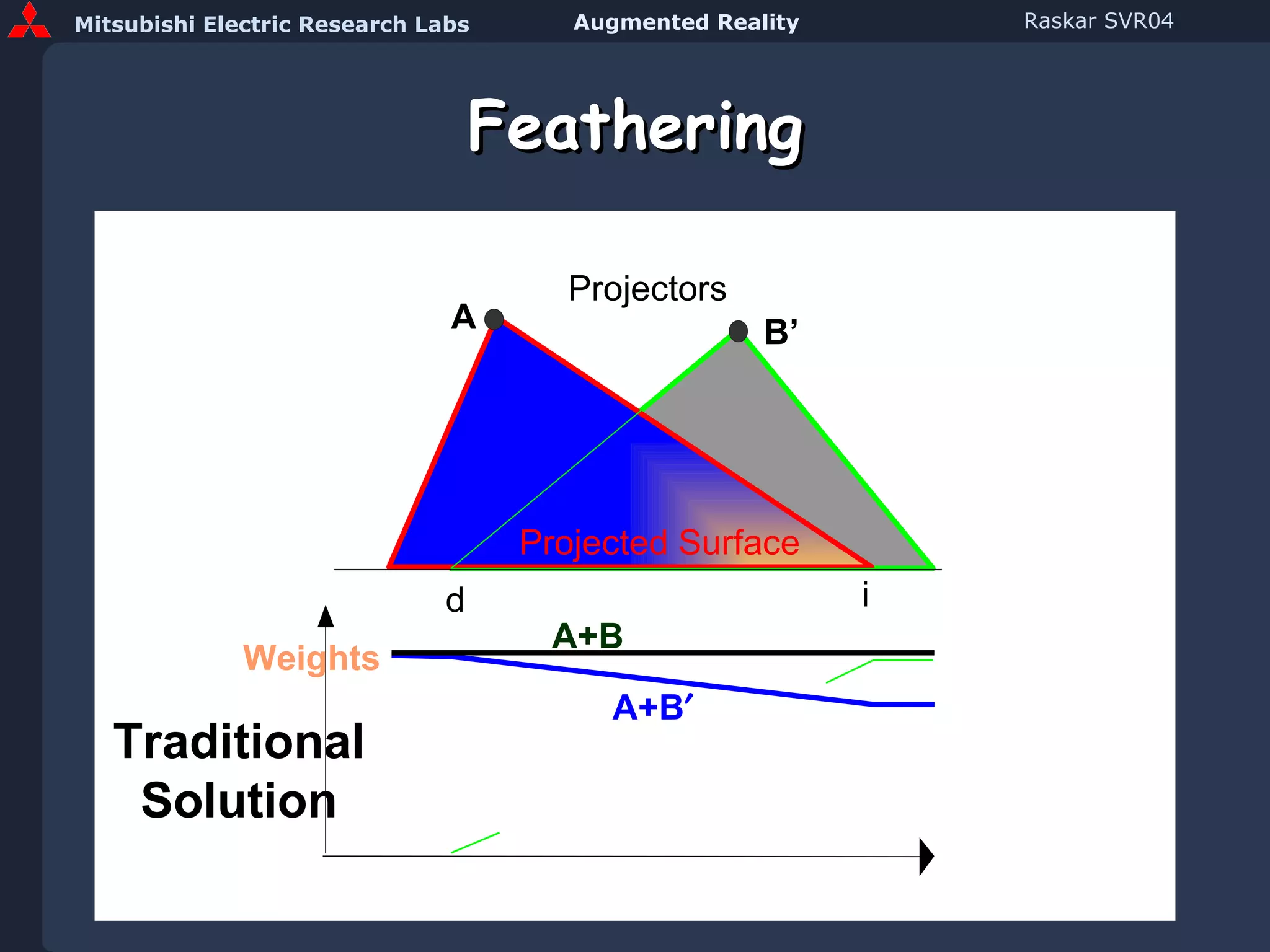
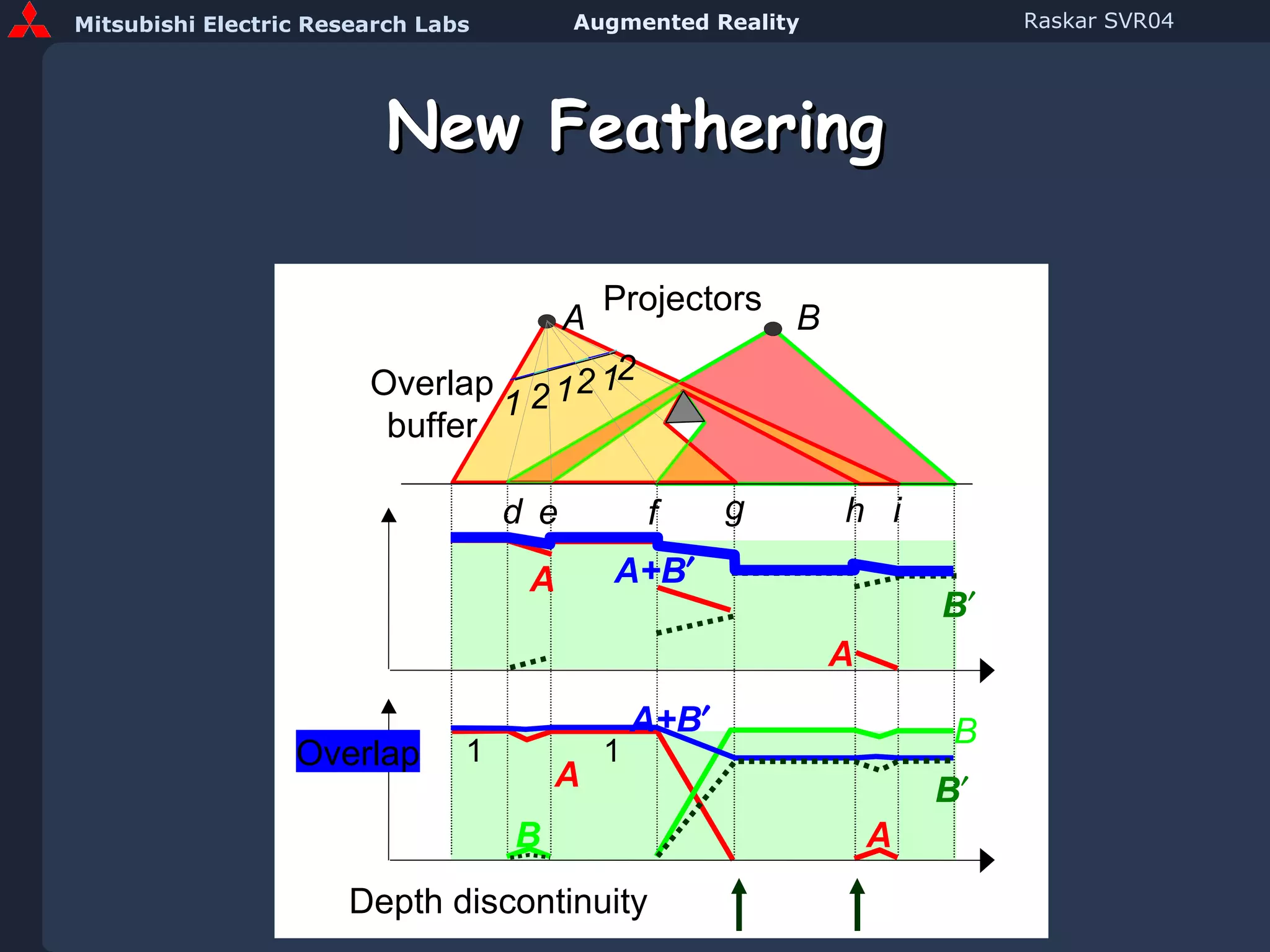
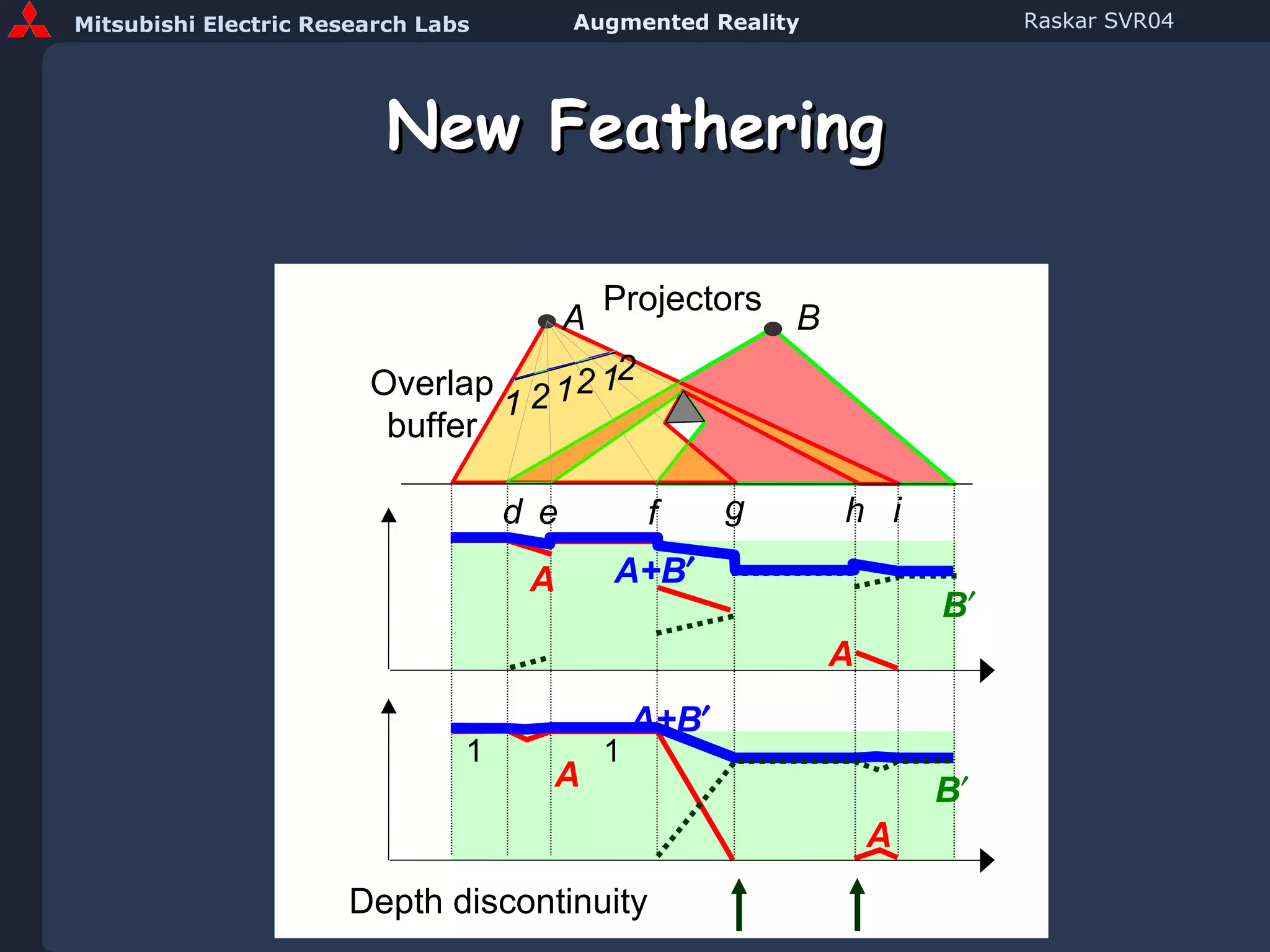
![Steps Preprocessing Scan 3D object and create model Approximately position projector(s) Compute pose Compute intensity correction Run time Render image [ I ] Apply intensity correction for object shape [ ] * [ I ] Apply feathering for projector overlap, [ ] * [ ] * [ I ]](https://image.slidesharecdn.com/svrraskar-090428161336-phpapp01/75/Svr-Raskar-45-2048.jpg)
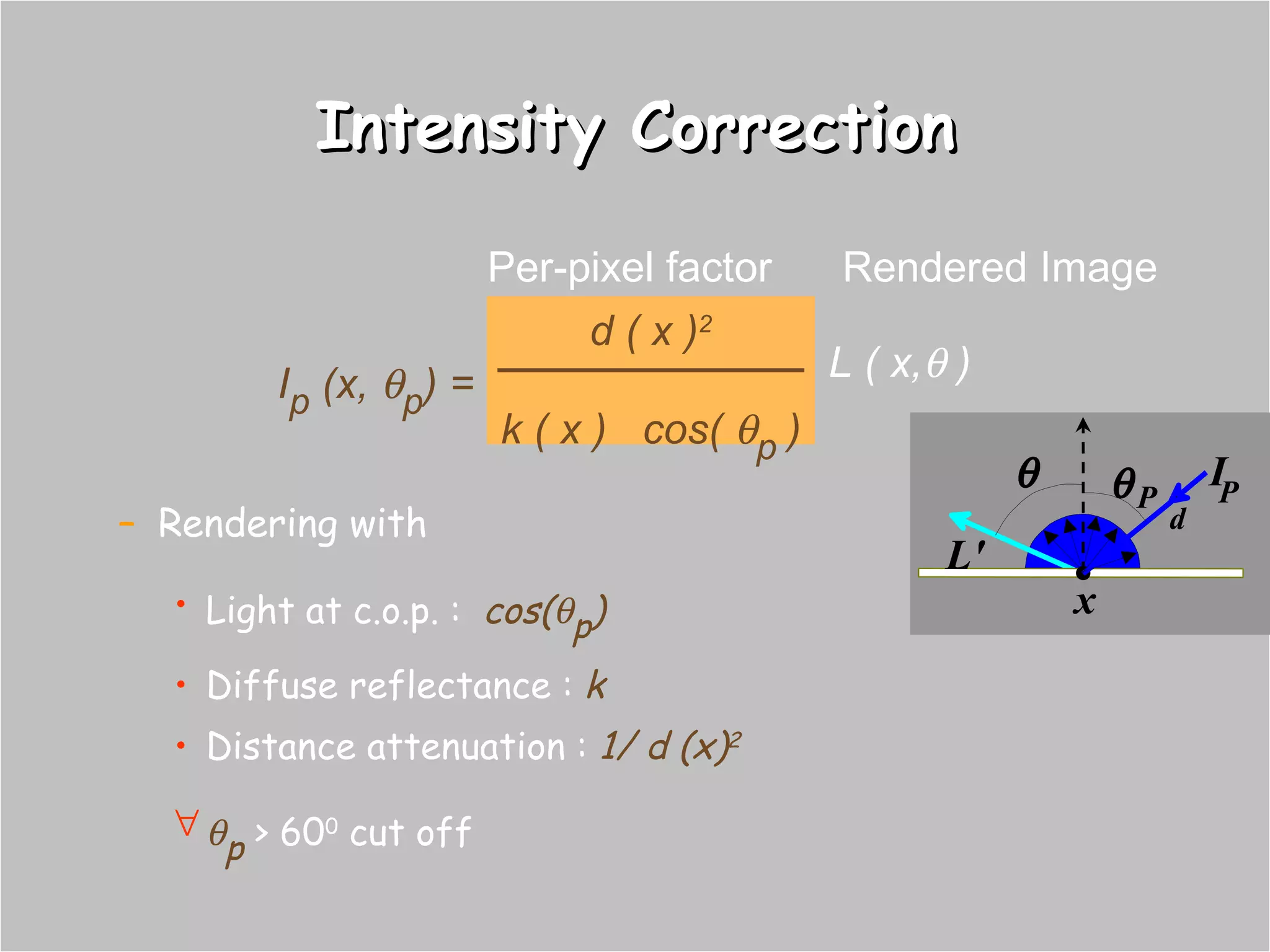
![Steps Preprocessing Scan 3D object and create model Approximately position projector(s) Compute pose Compute intensity correction Run time Render image [ I ] Intensity correction, [ ] * [ I ] Feathering, [ ] * [ ] * [ I ]](https://image.slidesharecdn.com/svrraskar-090428161336-phpapp01/75/Svr-Raskar-46-2048.jpg)
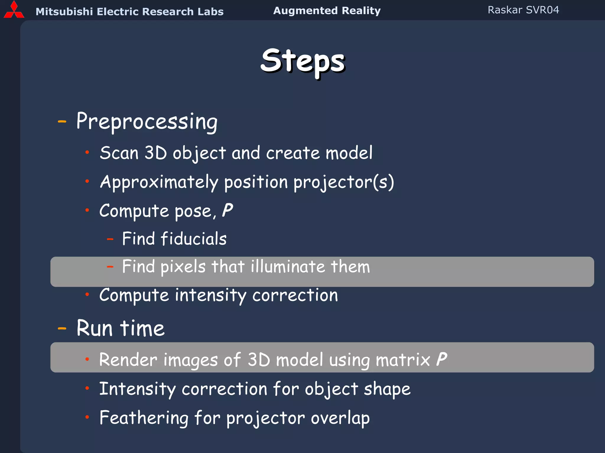
![Steps Preprocessing Scan 3D object and create model, G Approximately position projector(s) Compute pose, P Find fiducials Find pixels that illuminate them Find projector pose Run time Render 3D model G from P , [ I ] Intensity correction for object shape [ ] * [ I ] Feathering for projector overlap [ ] * [ ] * [ I ]](https://image.slidesharecdn.com/svrraskar-090428161336-phpapp01/75/Svr-Raskar-47-2048.jpg)

![Planar Multi-Projector Display [Raskar, Jeroen van Baar] 1 1 1 1 2 2 2 2 3 3 3 3 4 4 4 4 10 Seconds](https://image.slidesharecdn.com/svrraskar-090428161336-phpapp01/75/Svr-Raskar-59-2048.jpg)
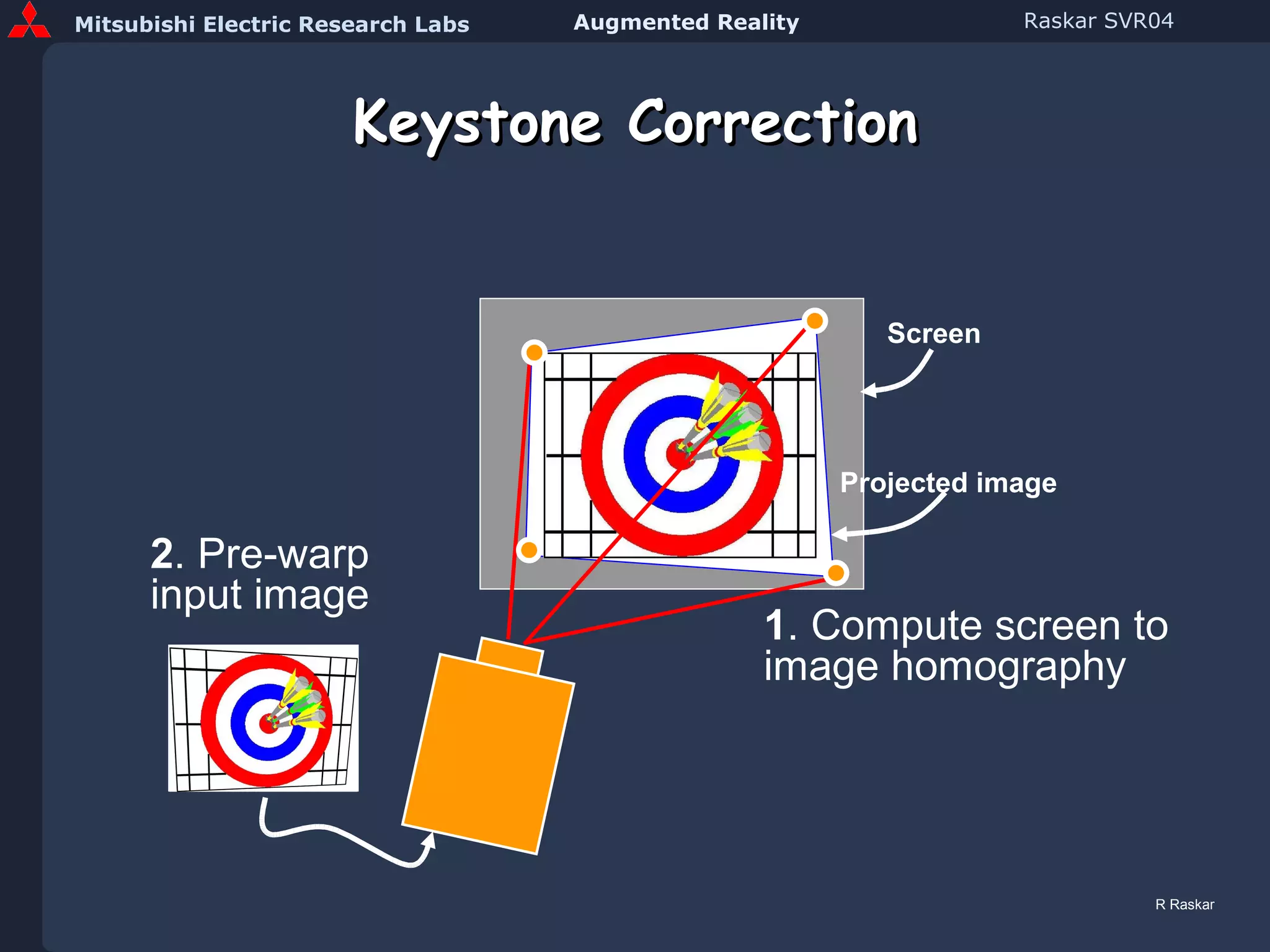
![Automatic Keystone Correction with Camera and Tilt Sensor 1 . Camera and tilt sensor to find projector pose 2 . Compute screen to image homography 3 . Pre-warp input image Screen Projected image R Raskar [Raskar and Beardsley01]](https://image.slidesharecdn.com/svrraskar-090428161336-phpapp01/75/Svr-Raskar-64-2048.jpg)
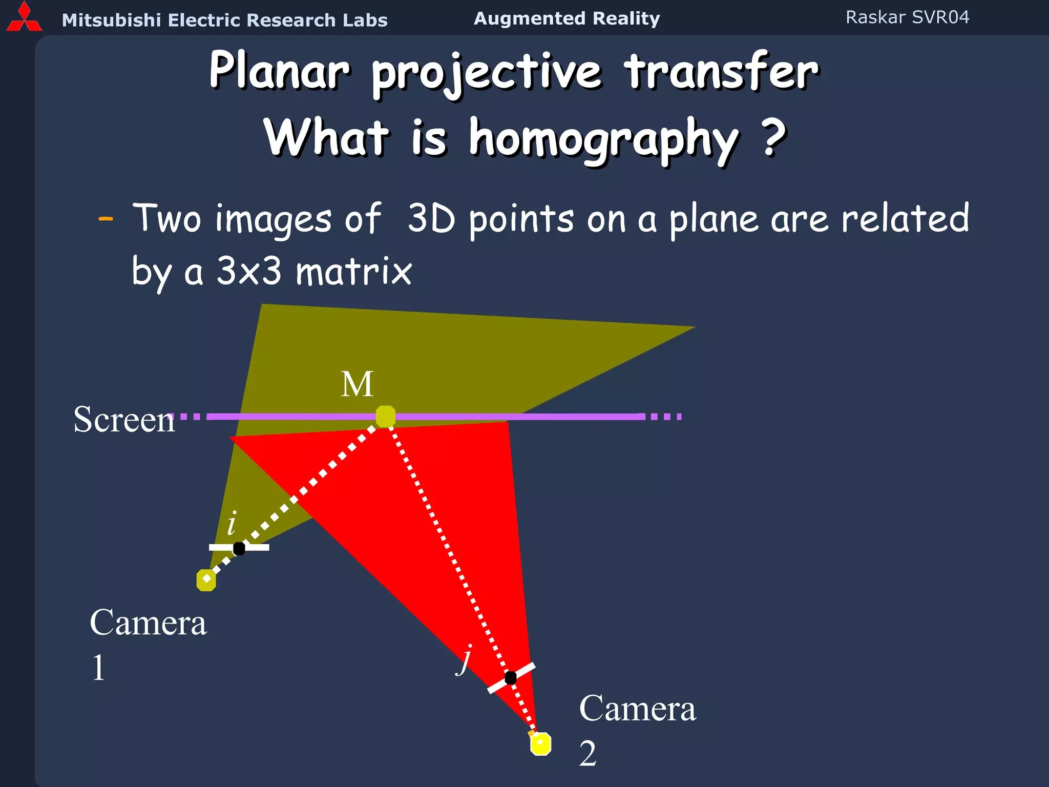
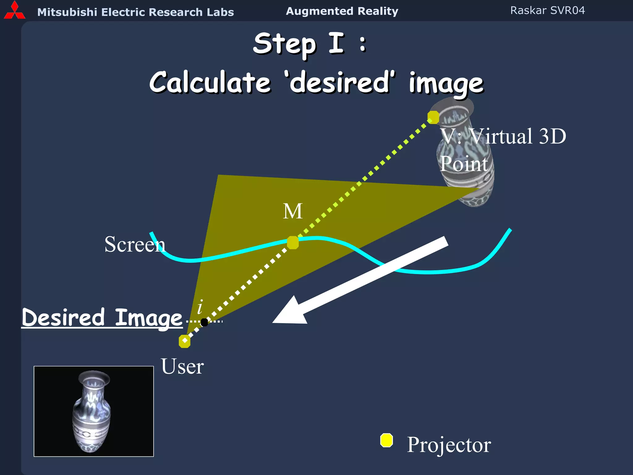
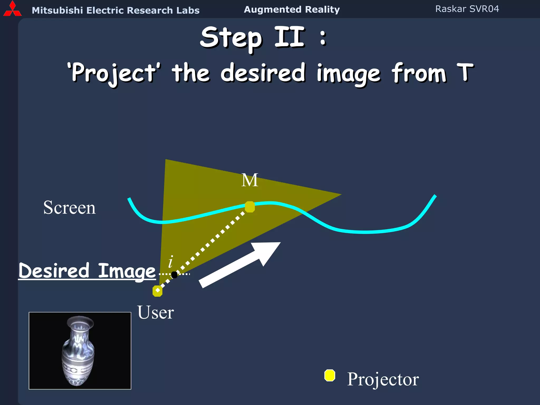
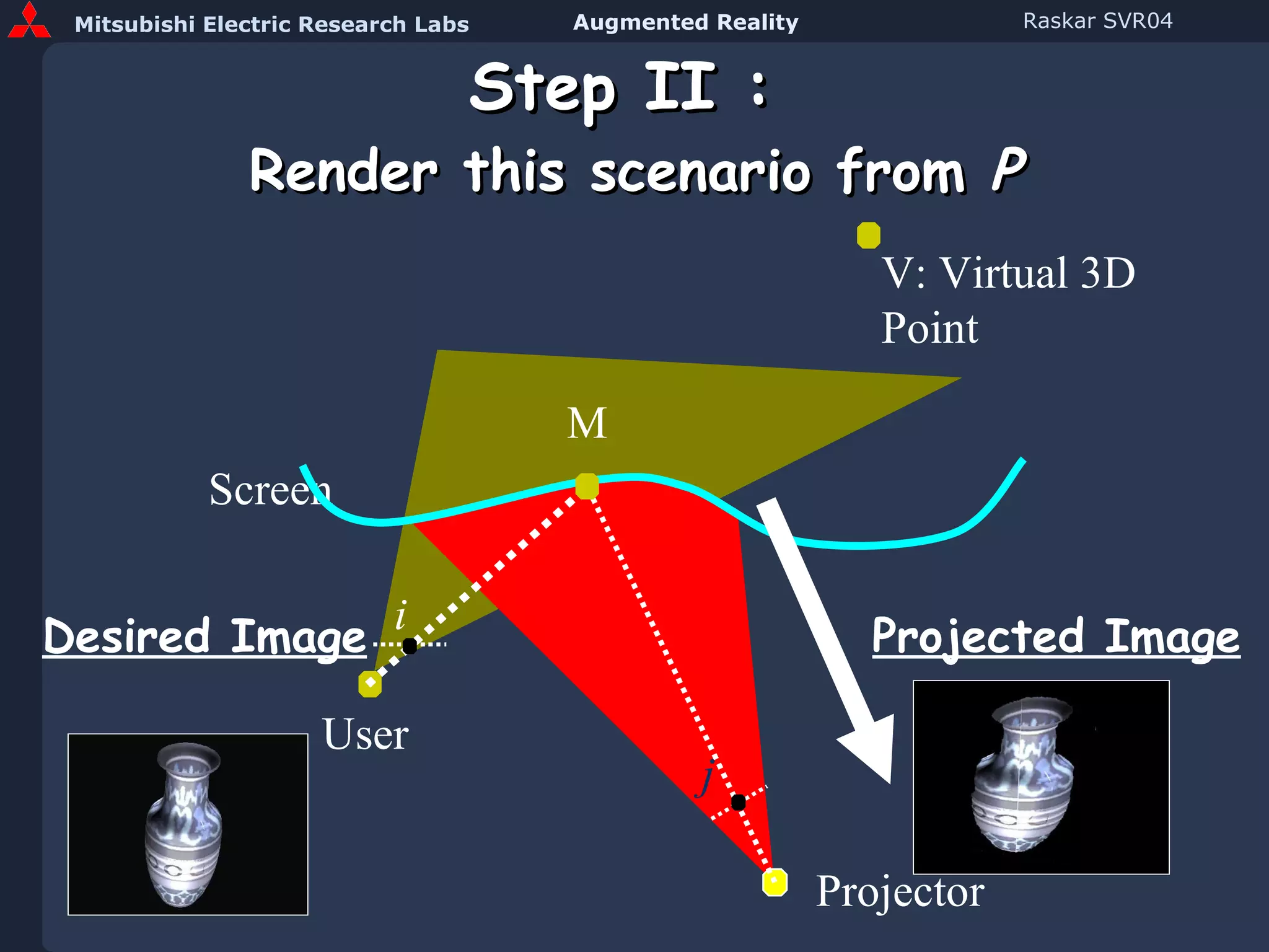
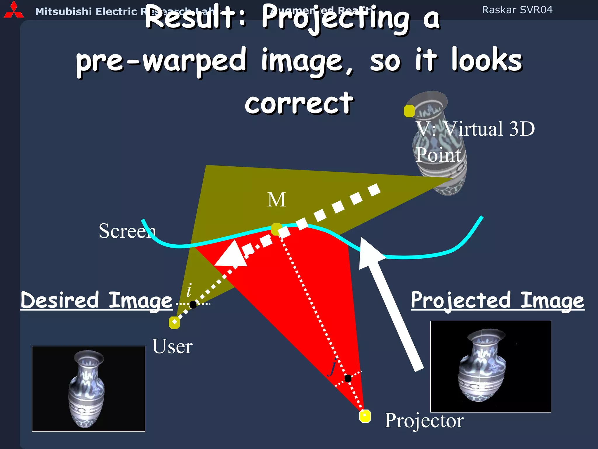
![Planar display surface Use homography ( A 3x3 ) User Single Projection Matrix ! V M i j A j = A i i = P T V ~ ~ P T j = [ A P T ] V ~](https://image.slidesharecdn.com/svrraskar-090428161336-phpapp01/75/Svr-Raskar-65-2048.jpg)


![Machine AR AR for cameras and machines Face Dome [Debevec 2001] 4D lighting [MPI, MERL]](https://image.slidesharecdn.com/svrraskar-090428161336-phpapp01/75/Svr-Raskar-117-2048.jpg)
![Projector-Camera Workshop June 2005 www.PROCAMS.org Web Page : http://raskar.com/Projector/ Projector mailing list [email_address] “ subscribe projector”](https://image.slidesharecdn.com/svrraskar-090428161336-phpapp01/75/Svr-Raskar-120-2048.jpg)
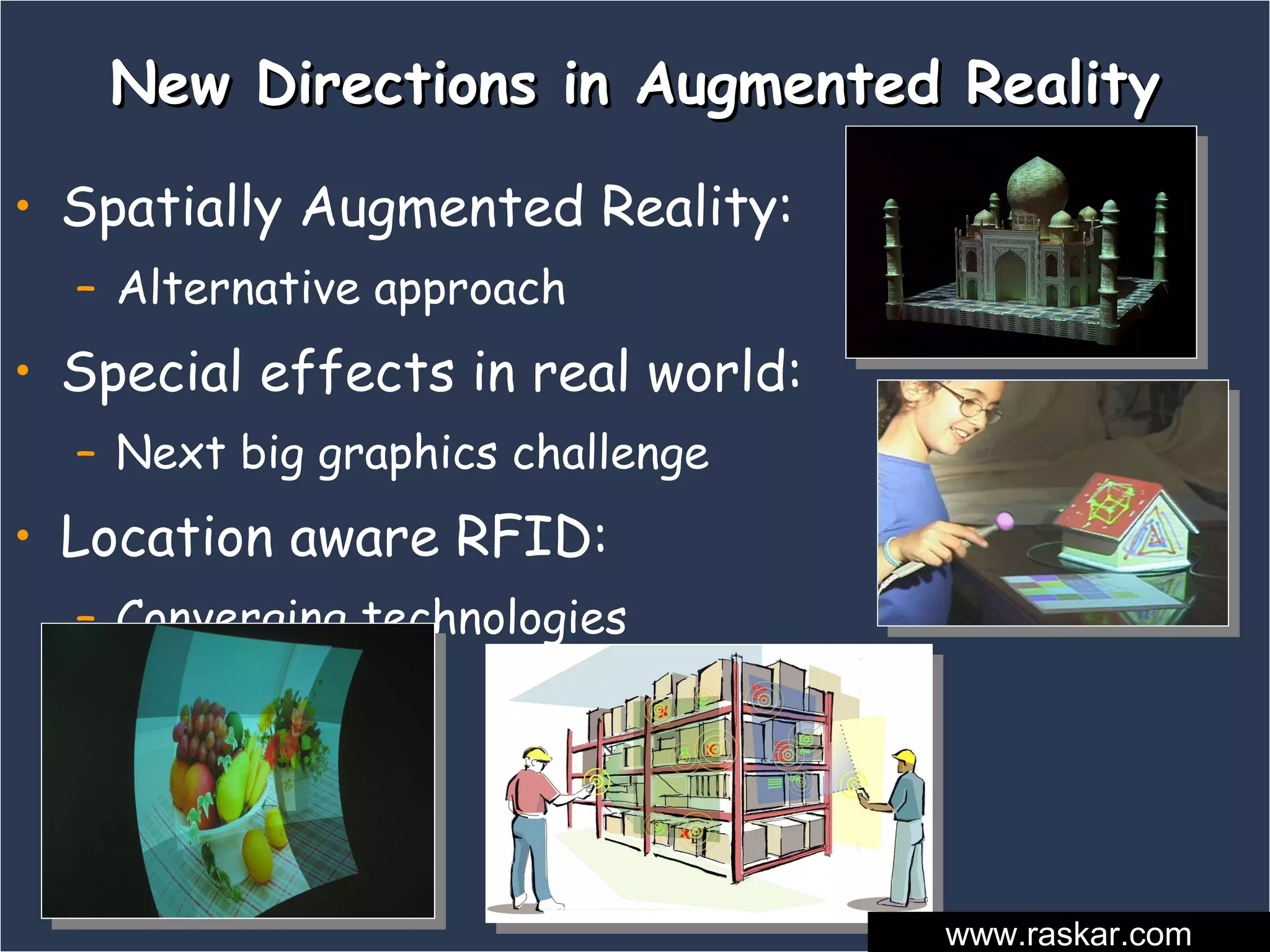
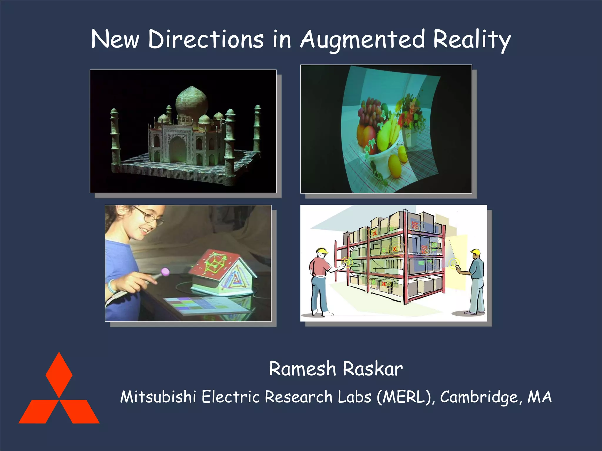
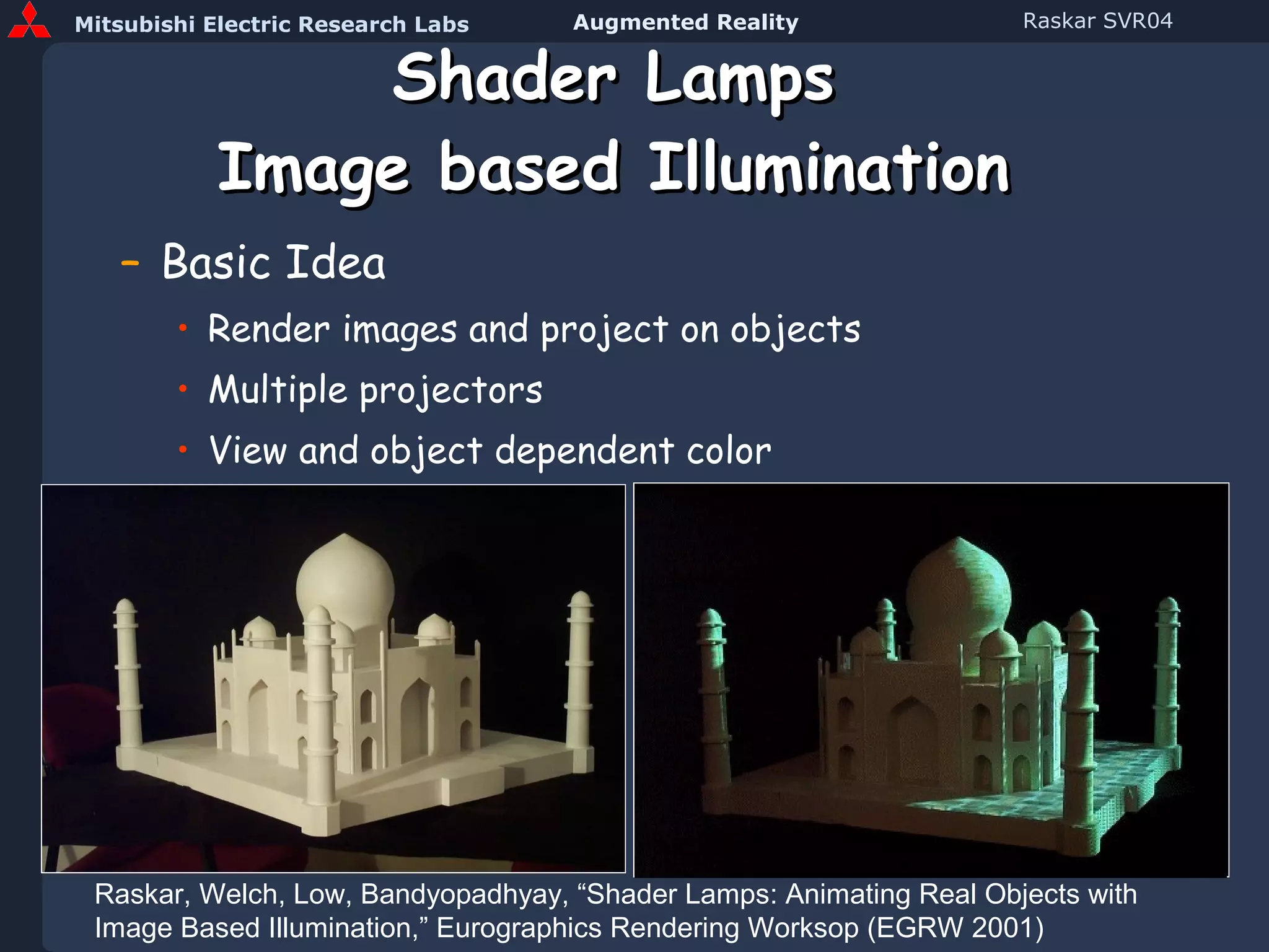


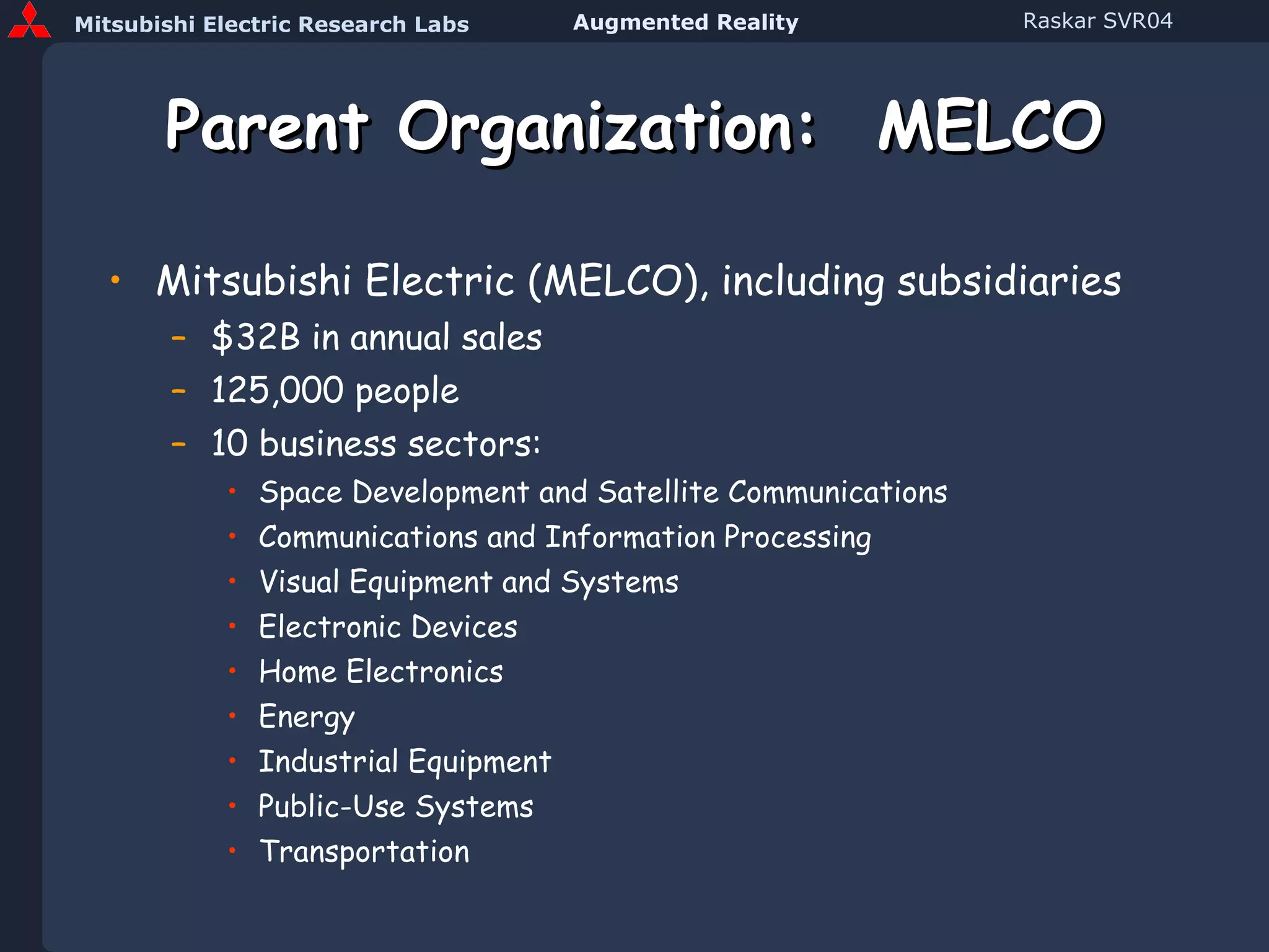
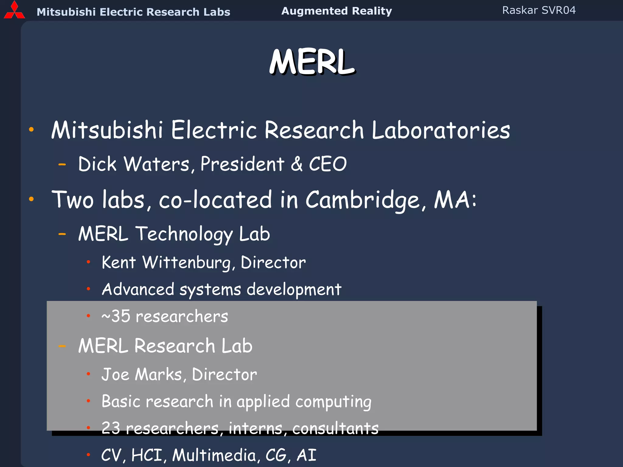
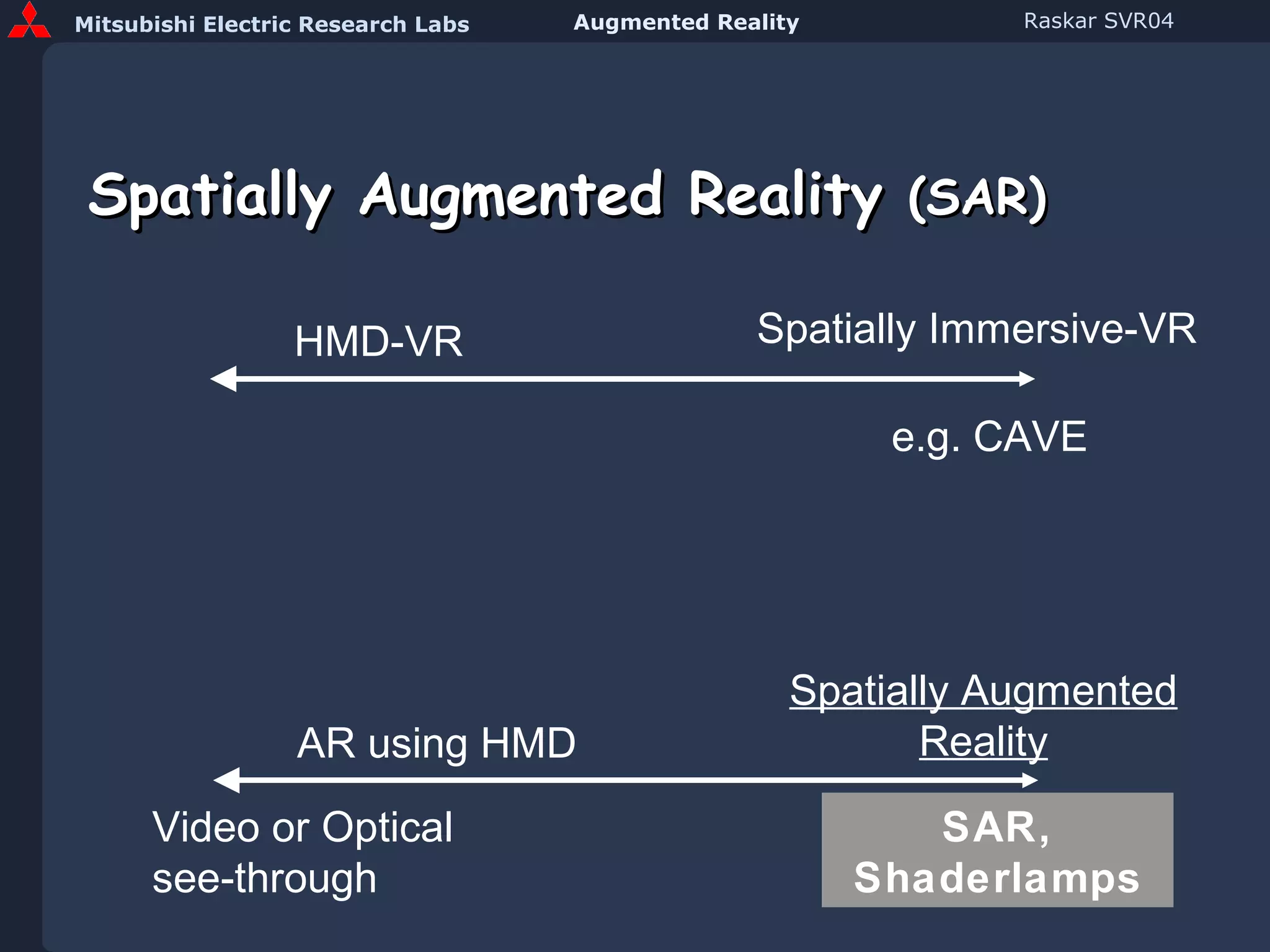
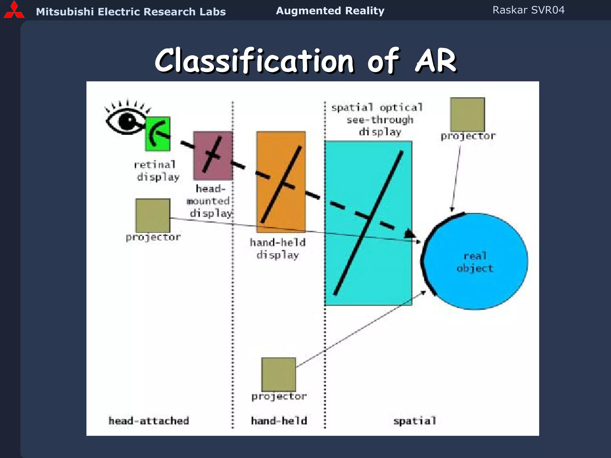
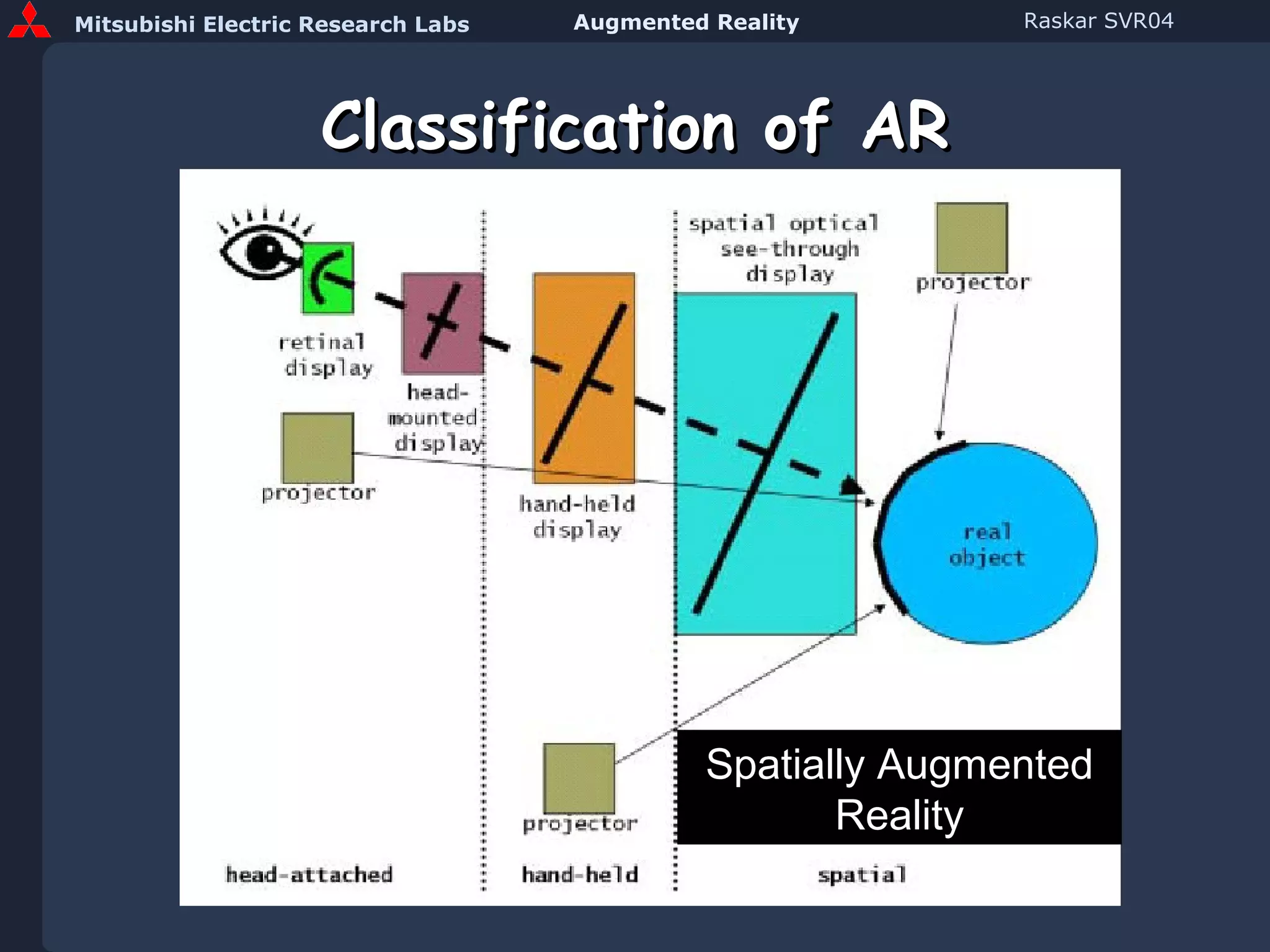
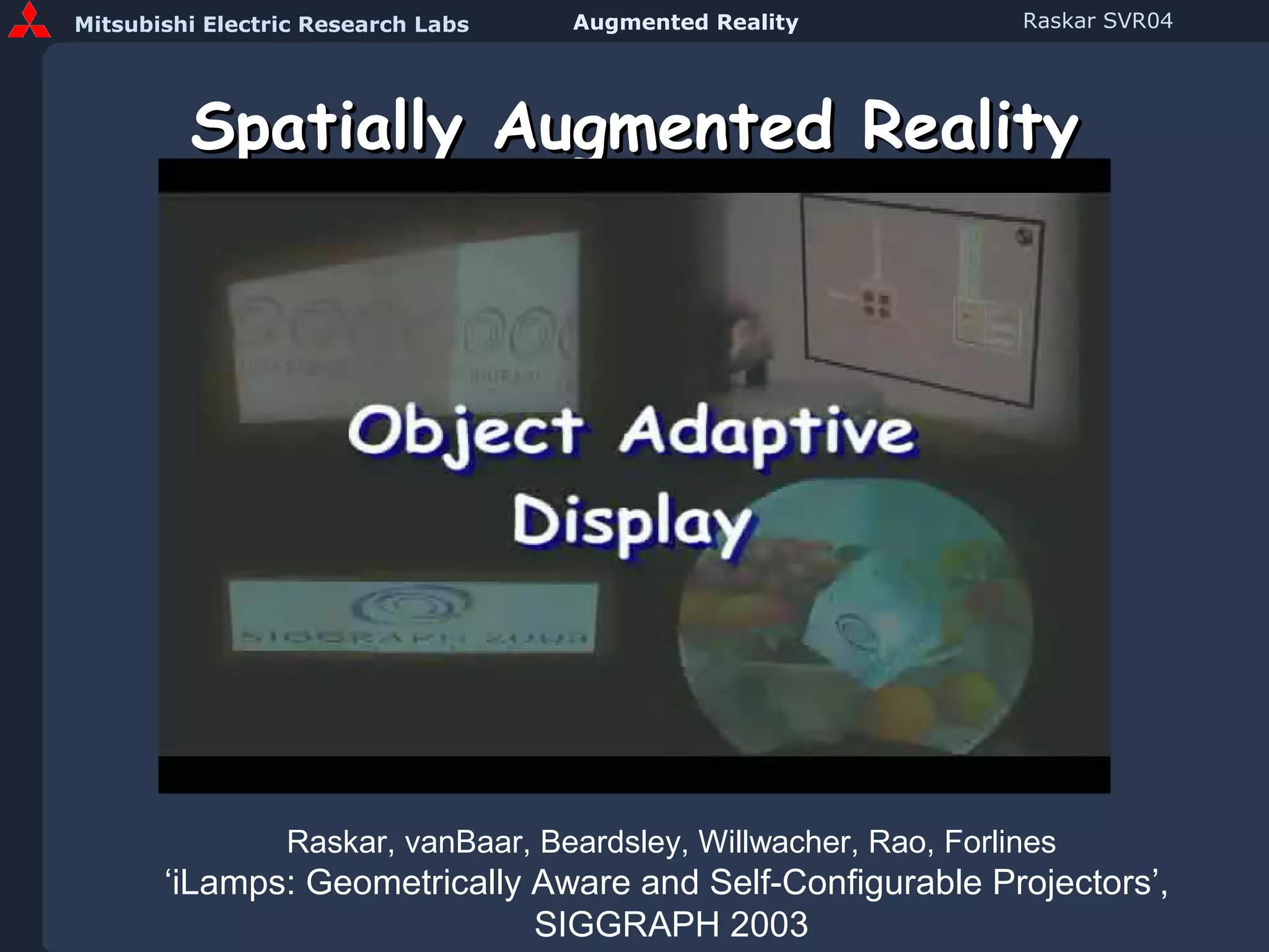
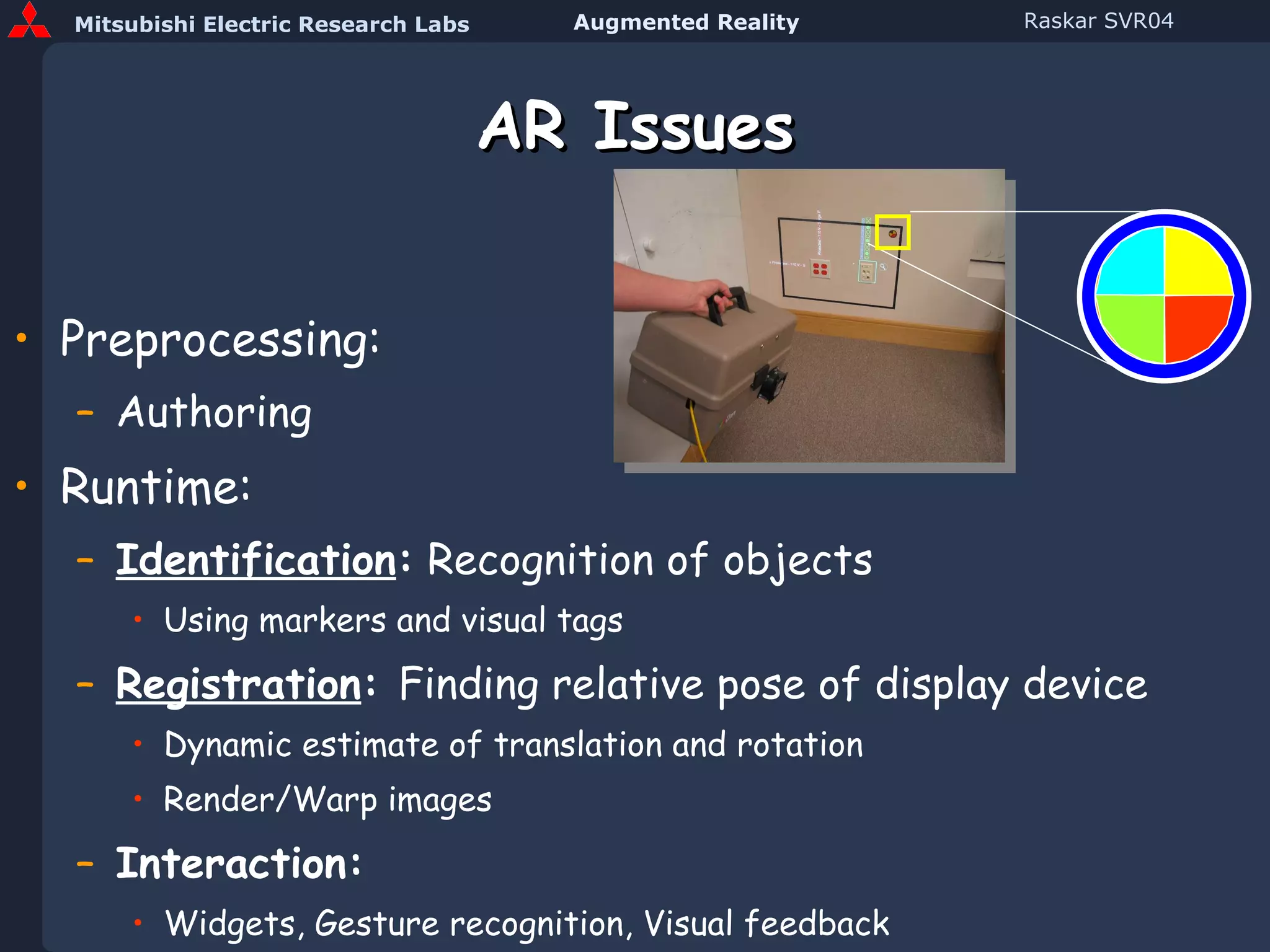
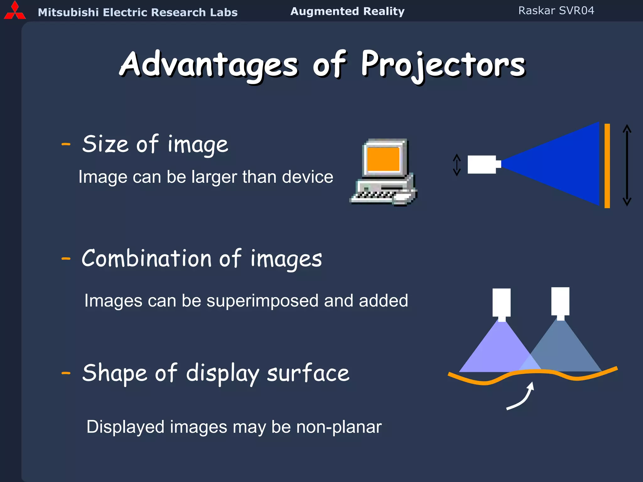
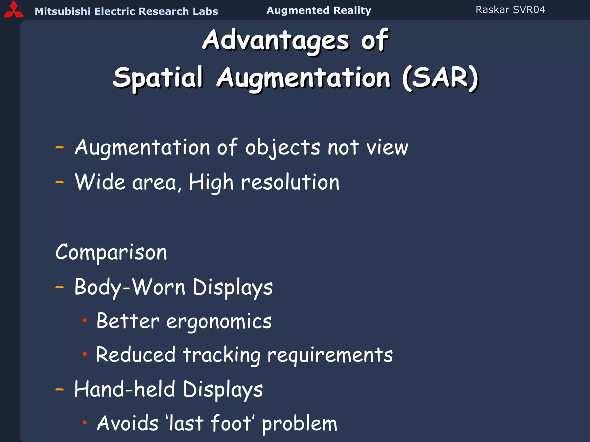
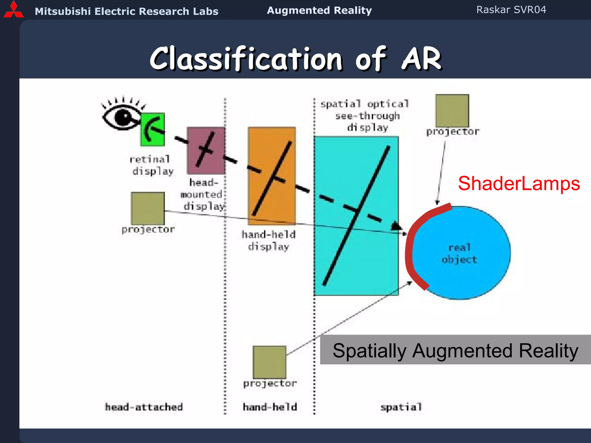
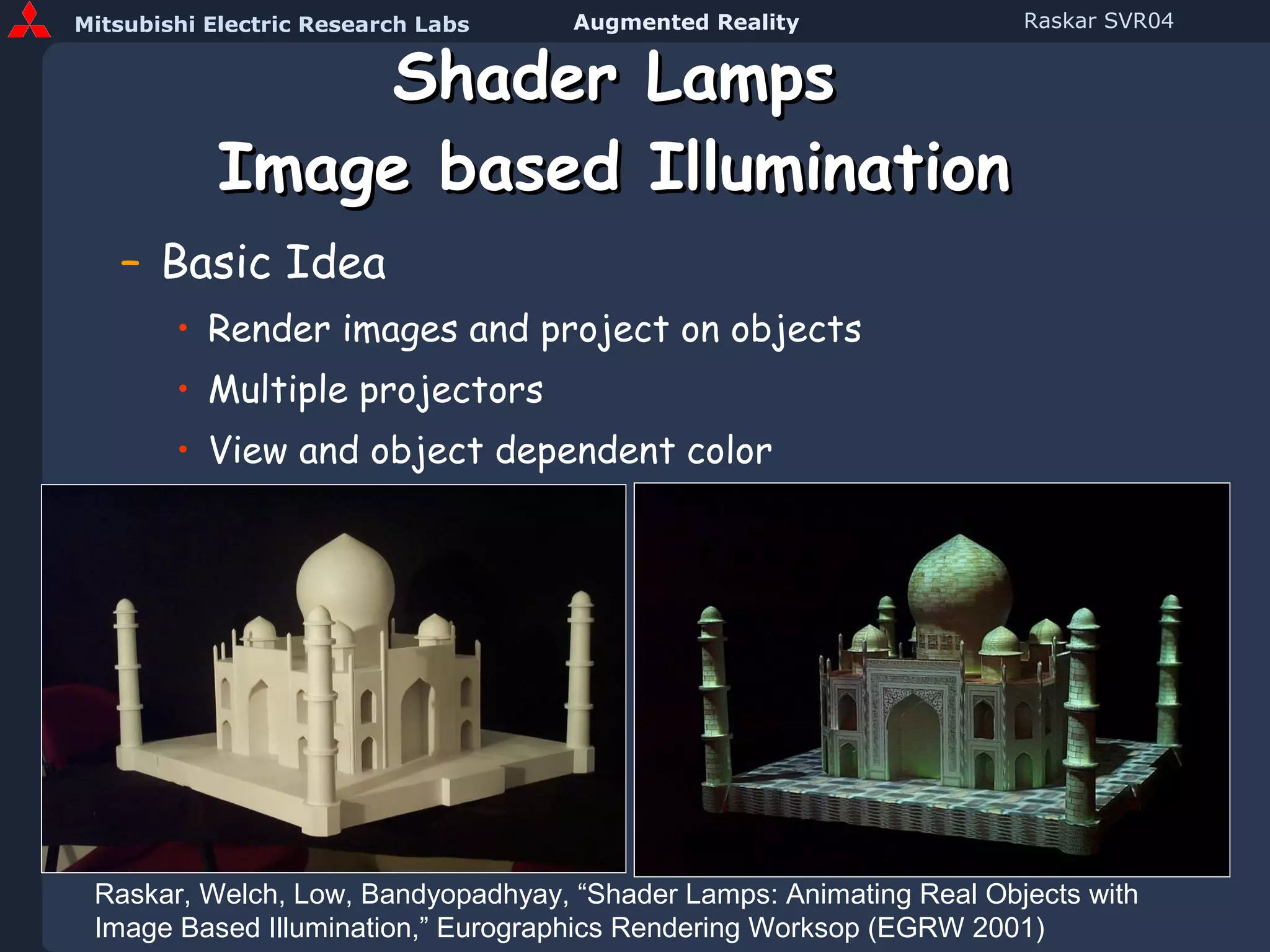
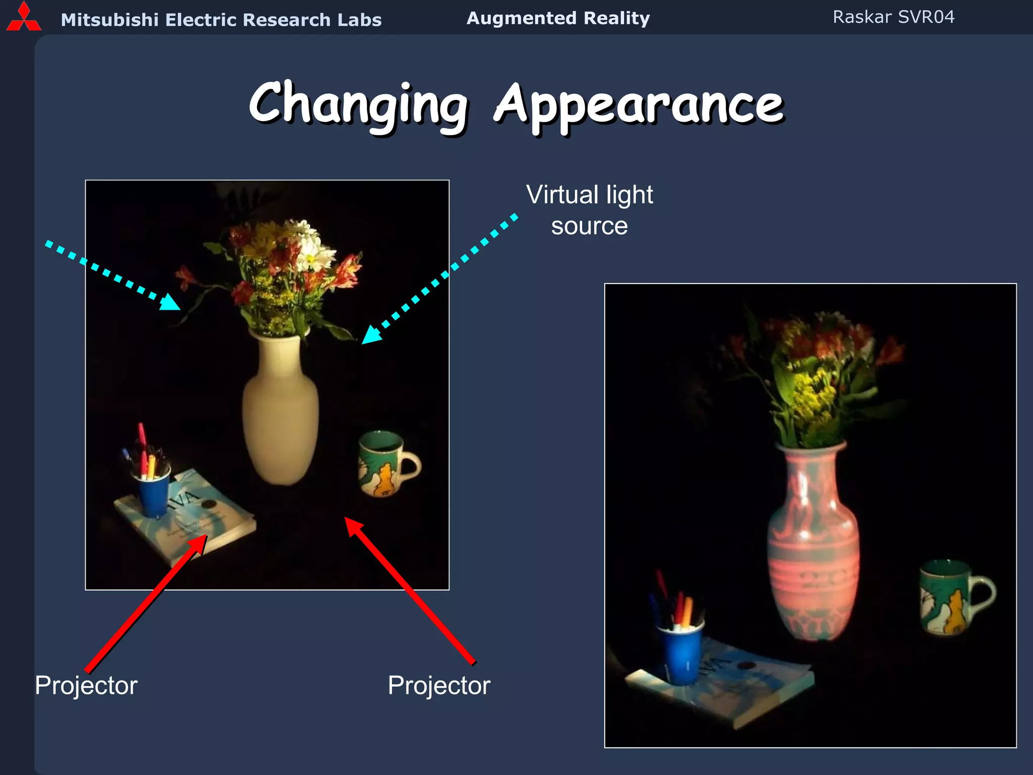
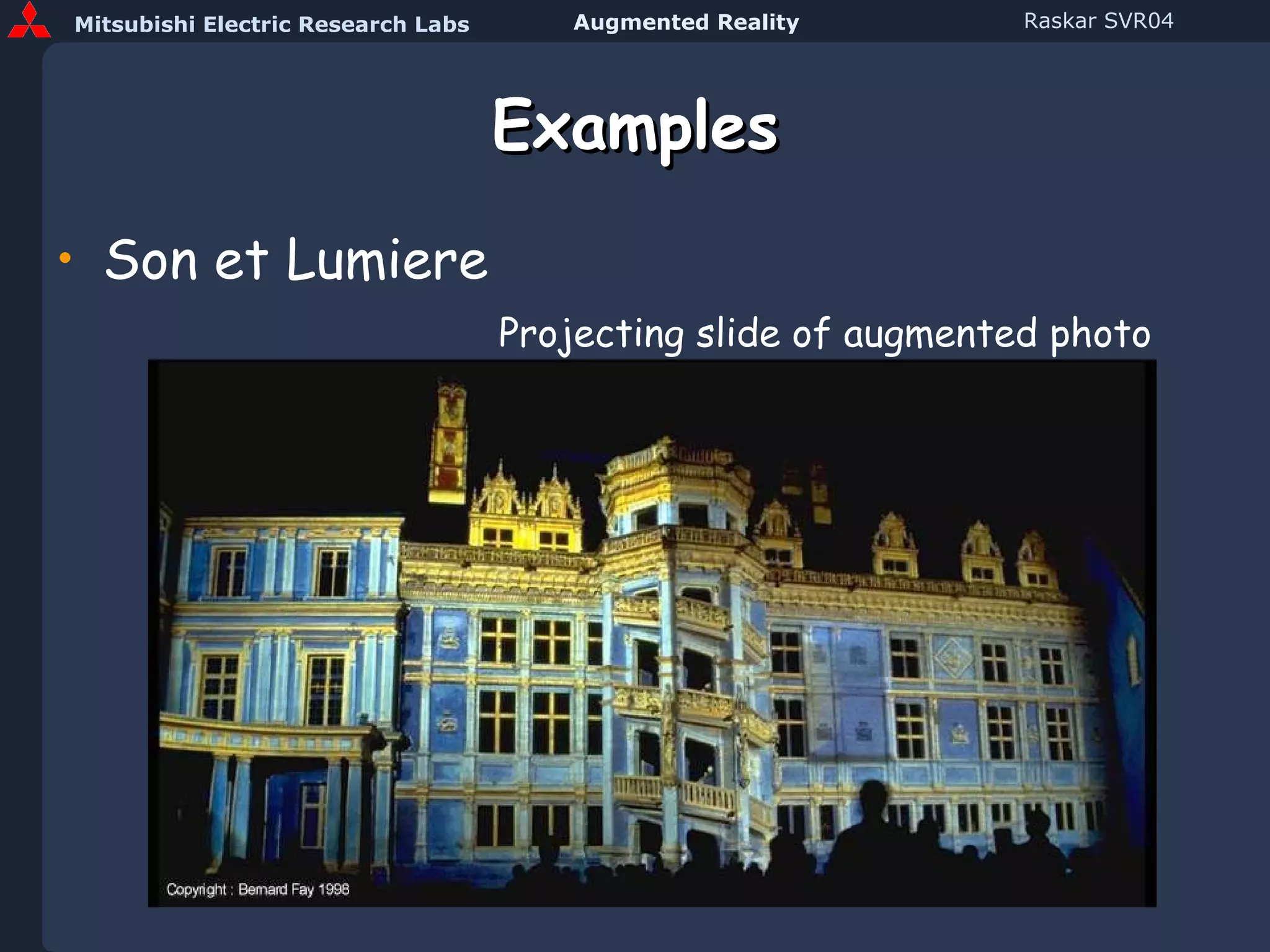
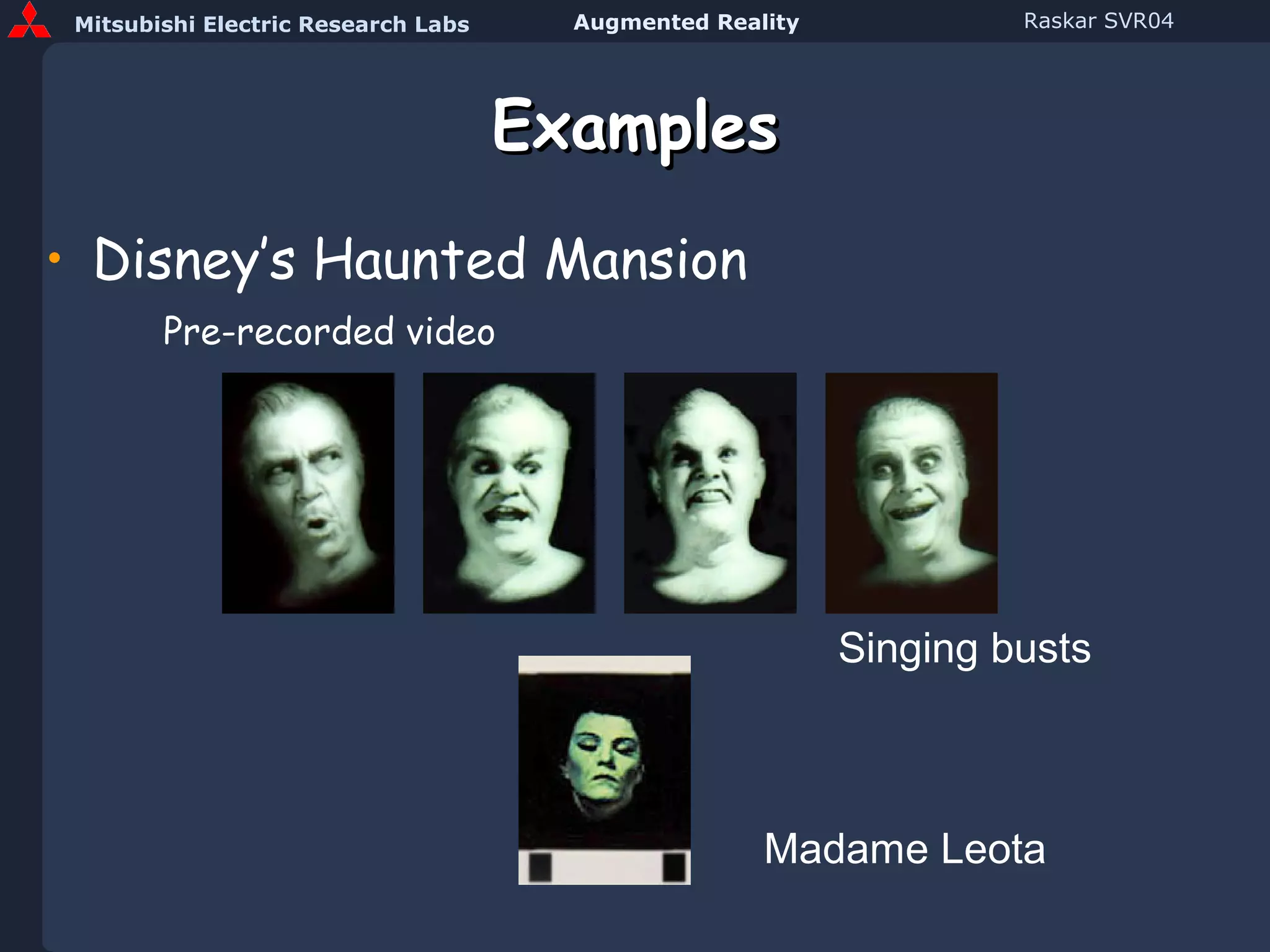
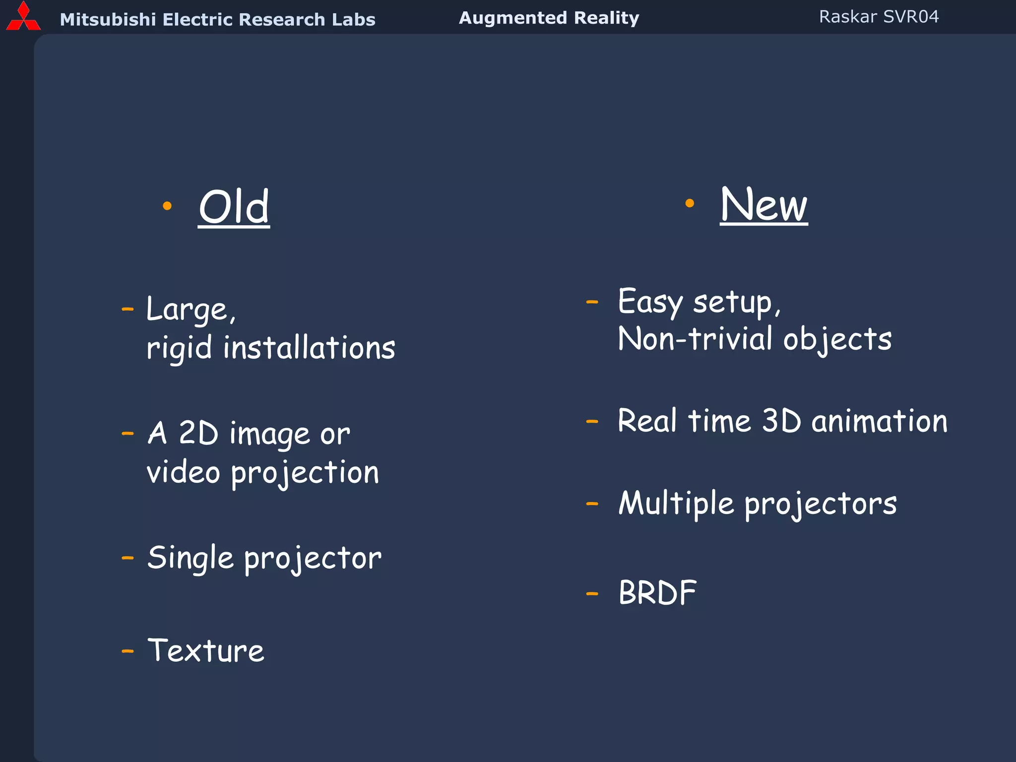
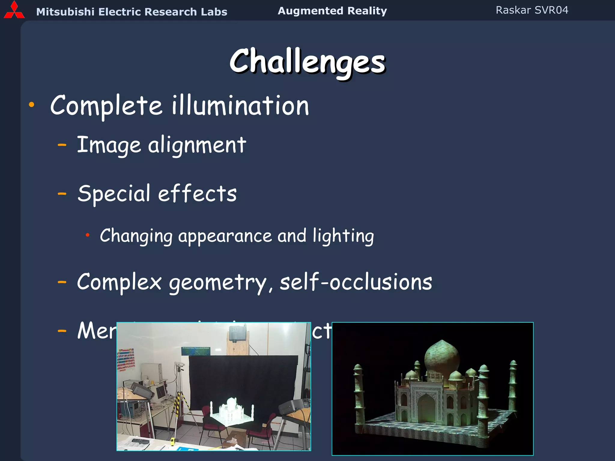
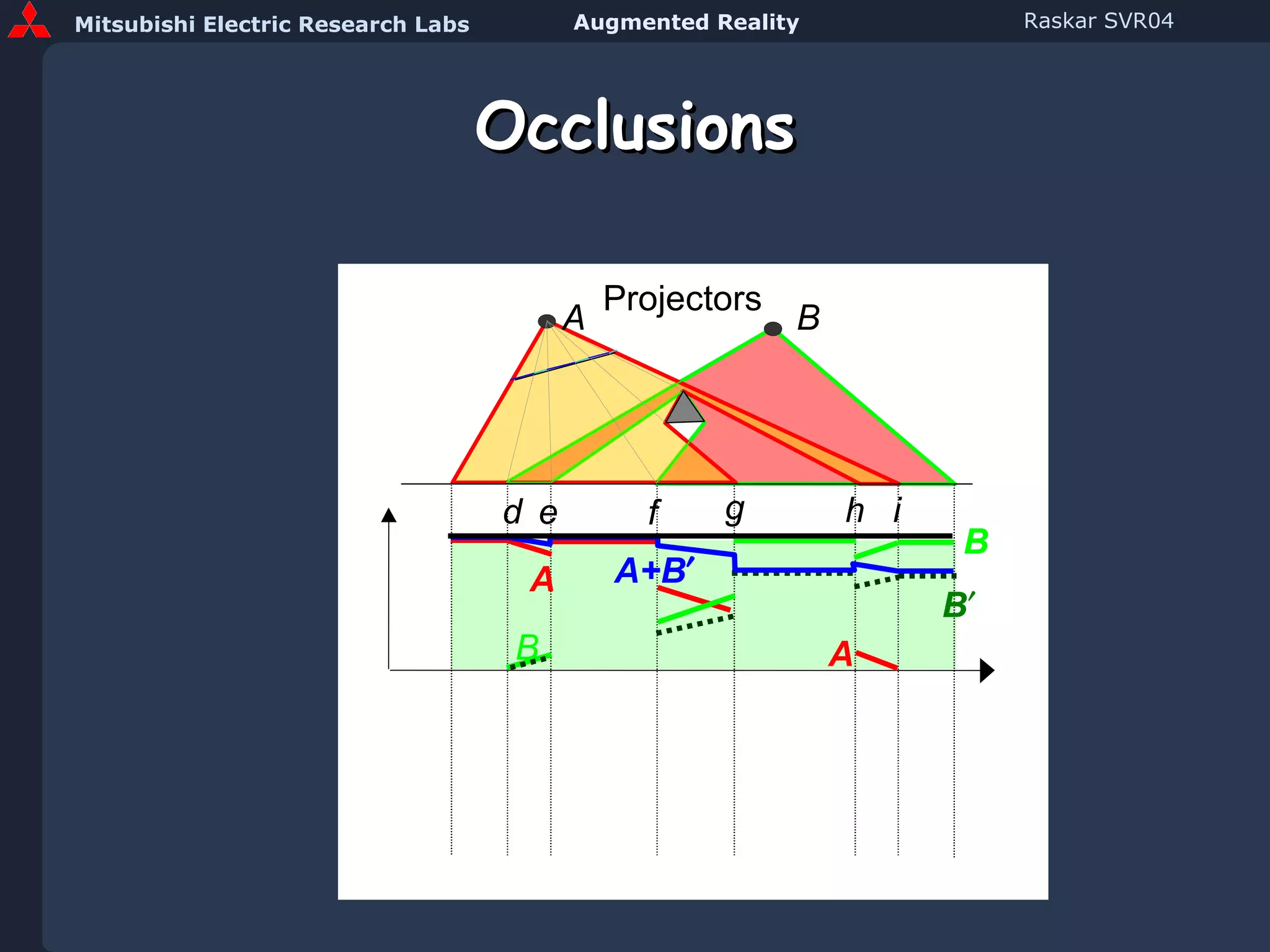
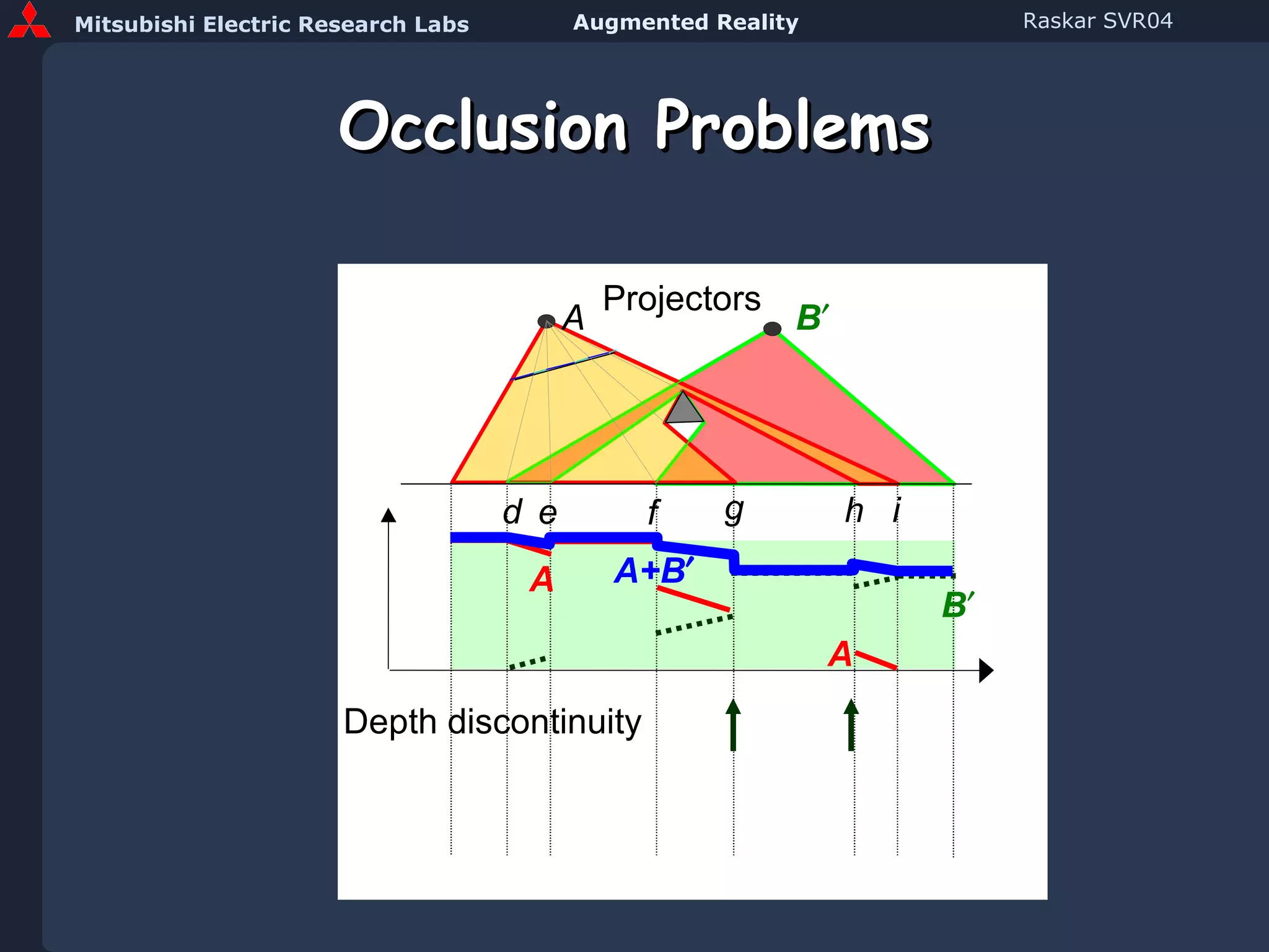
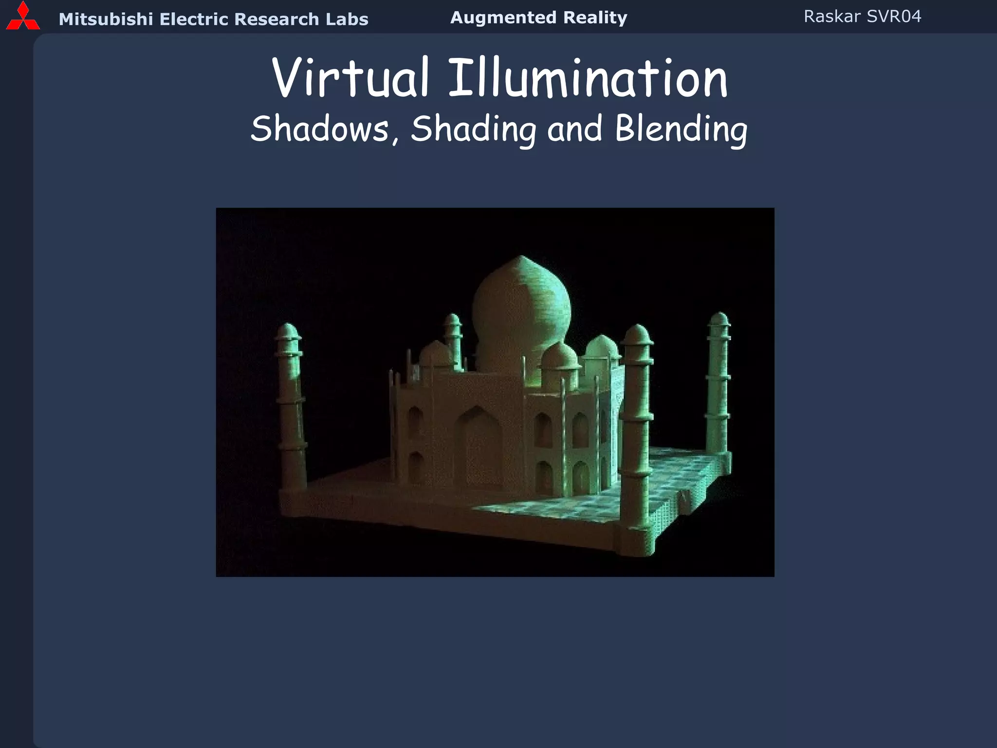
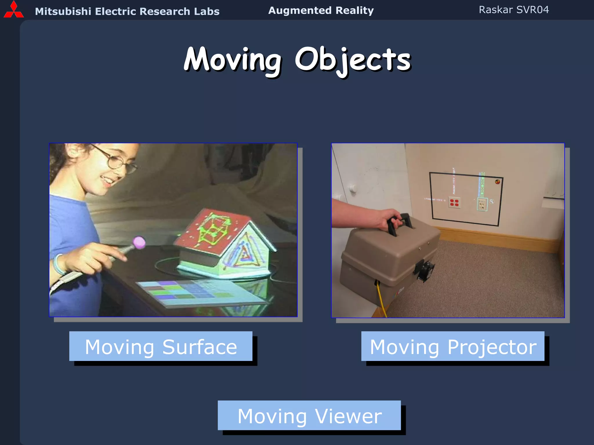
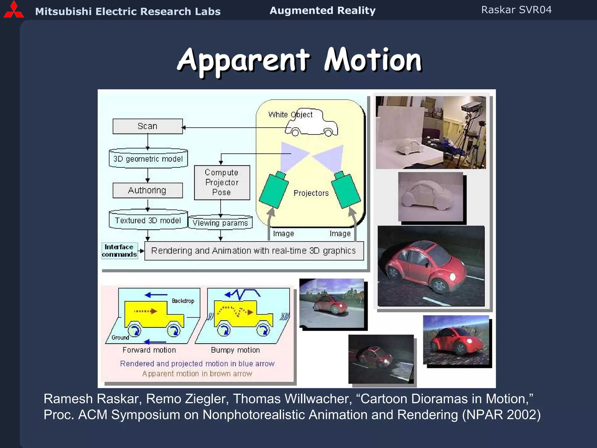
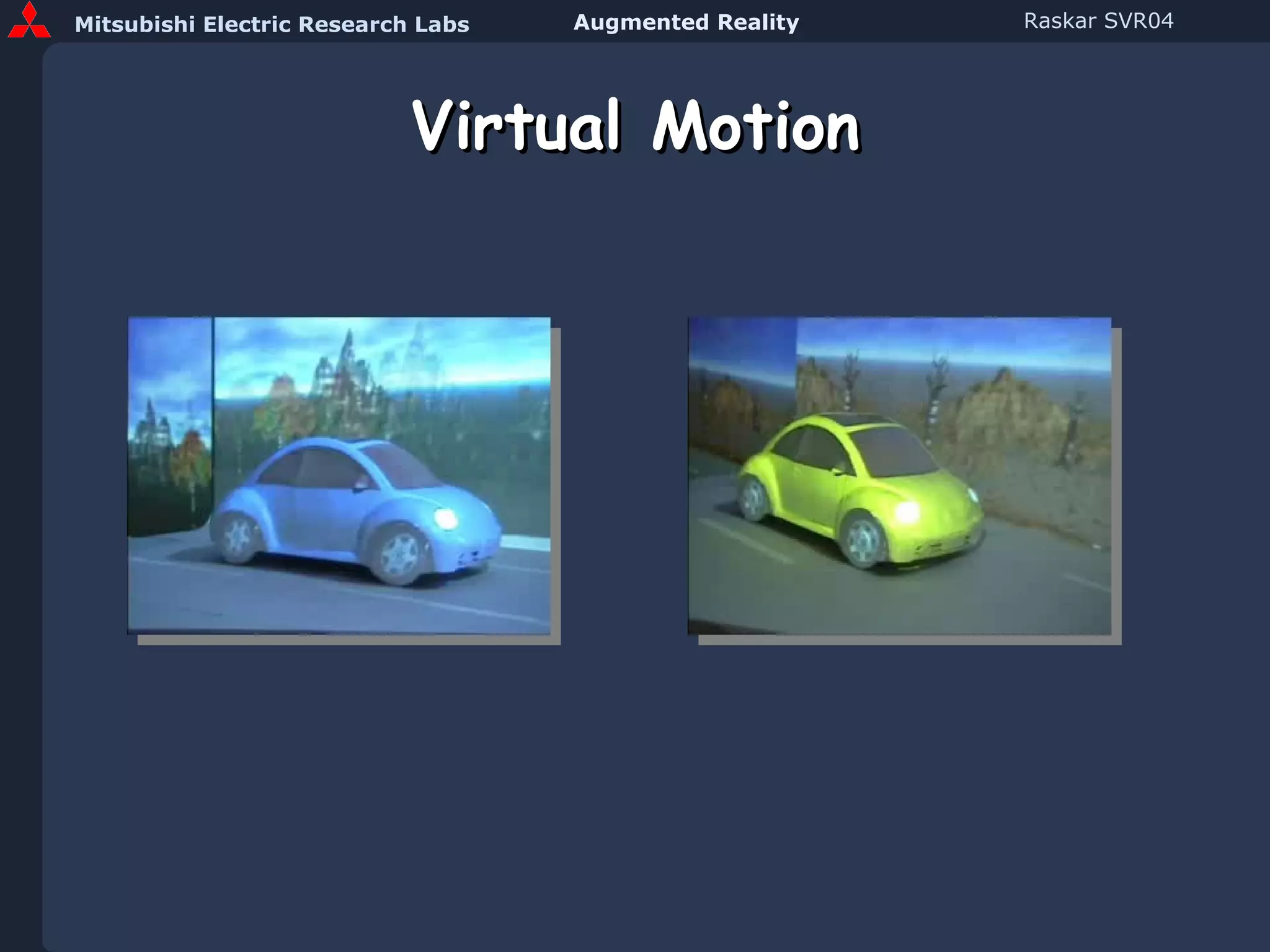
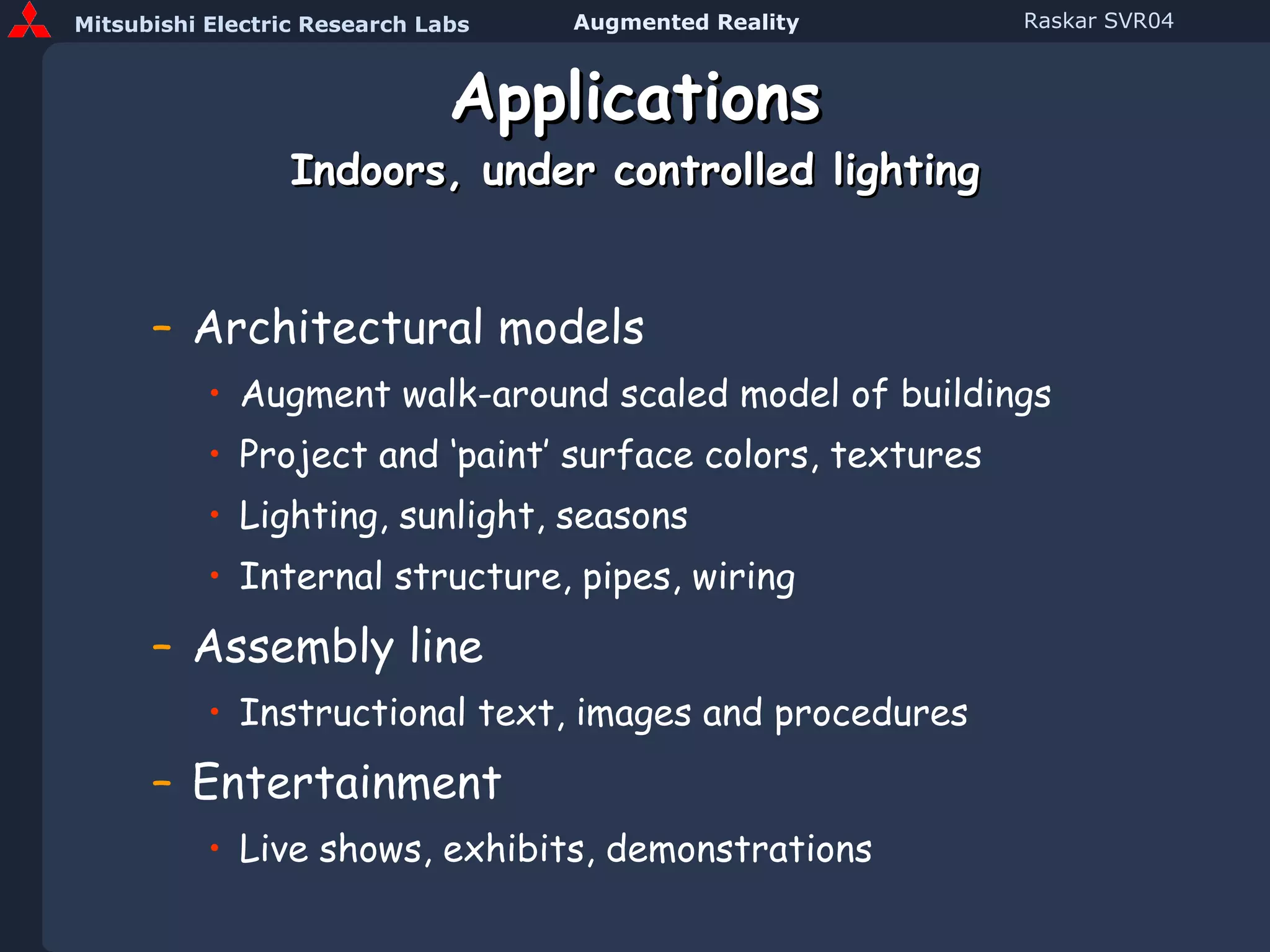
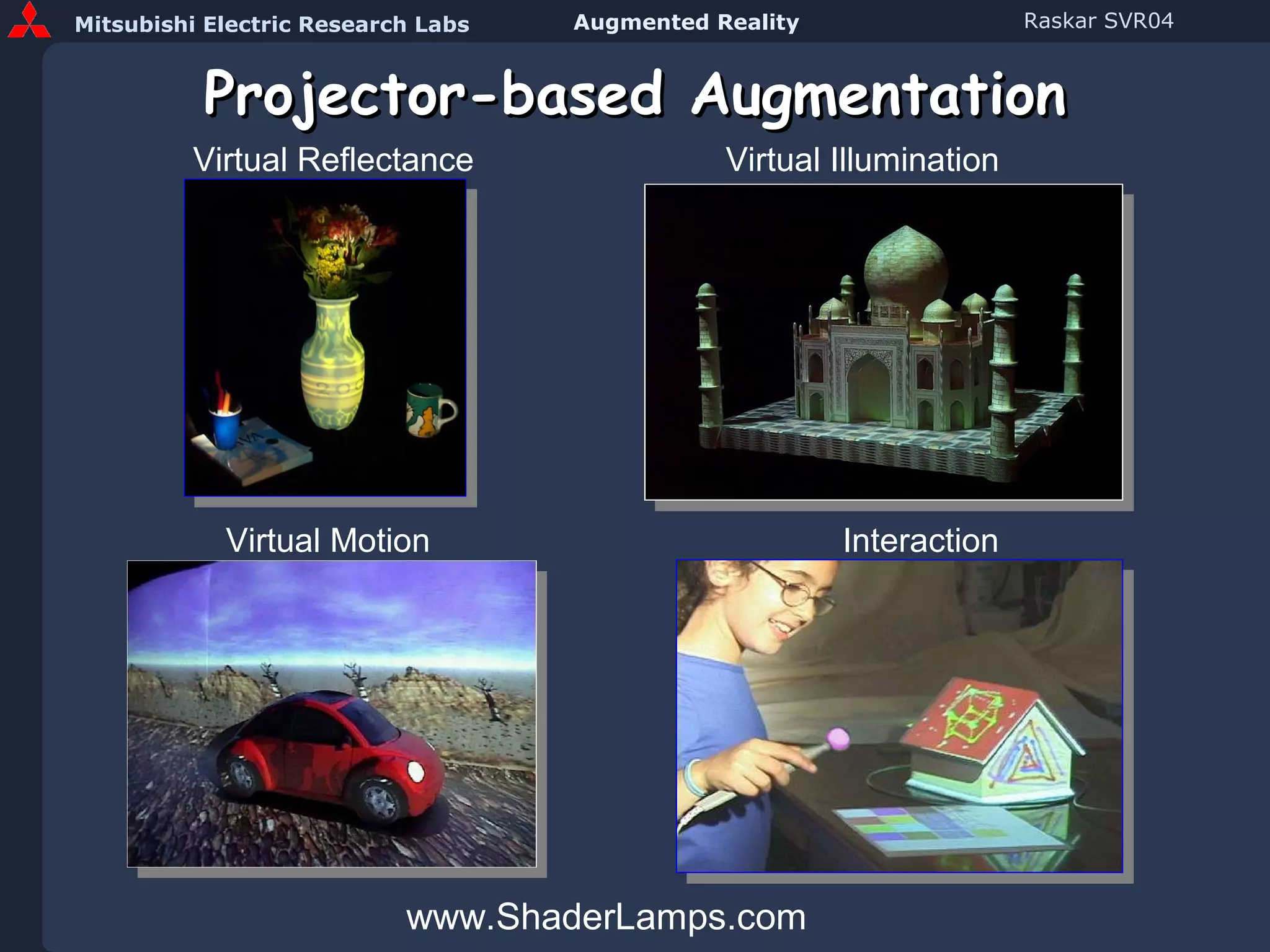
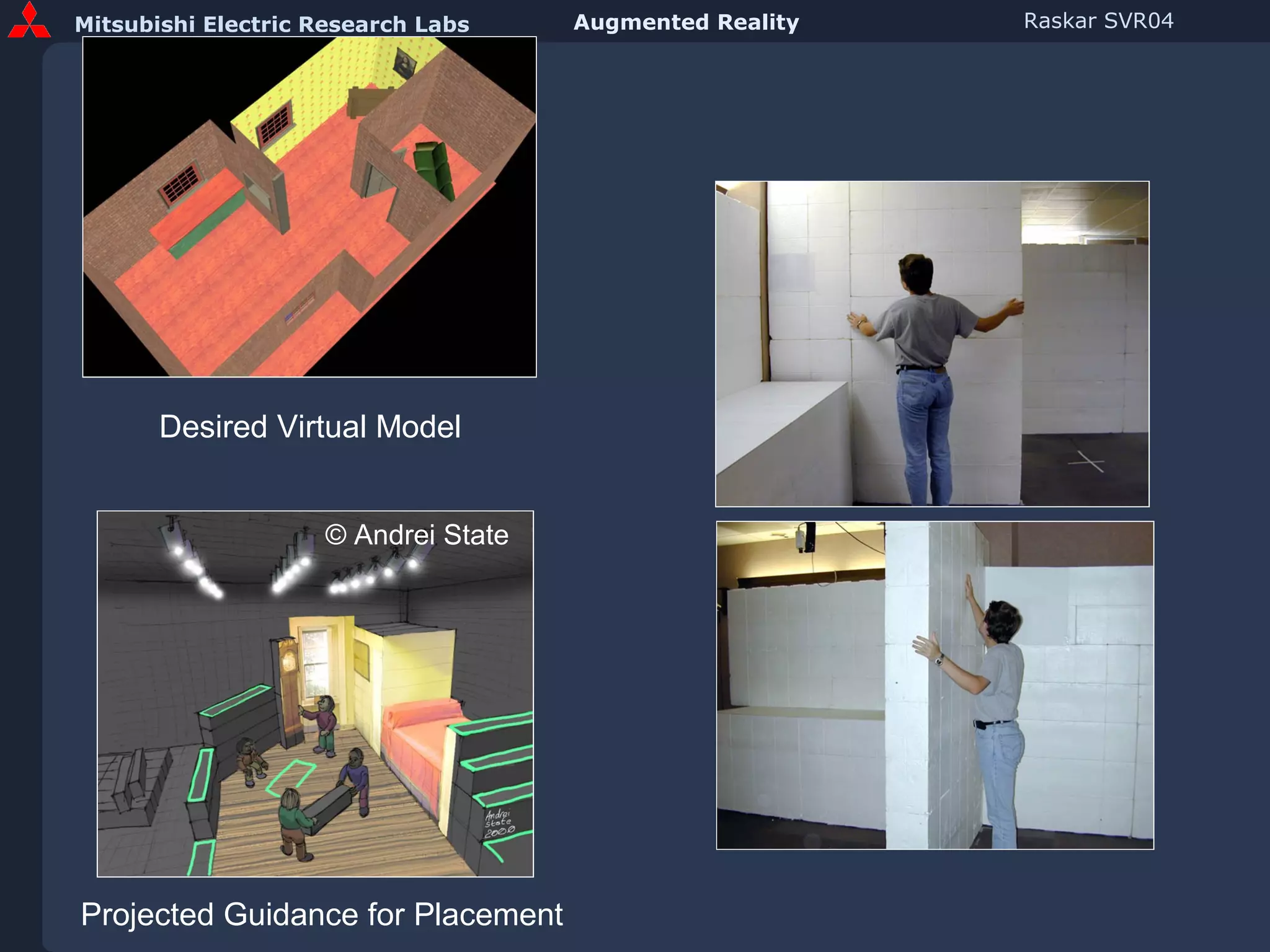
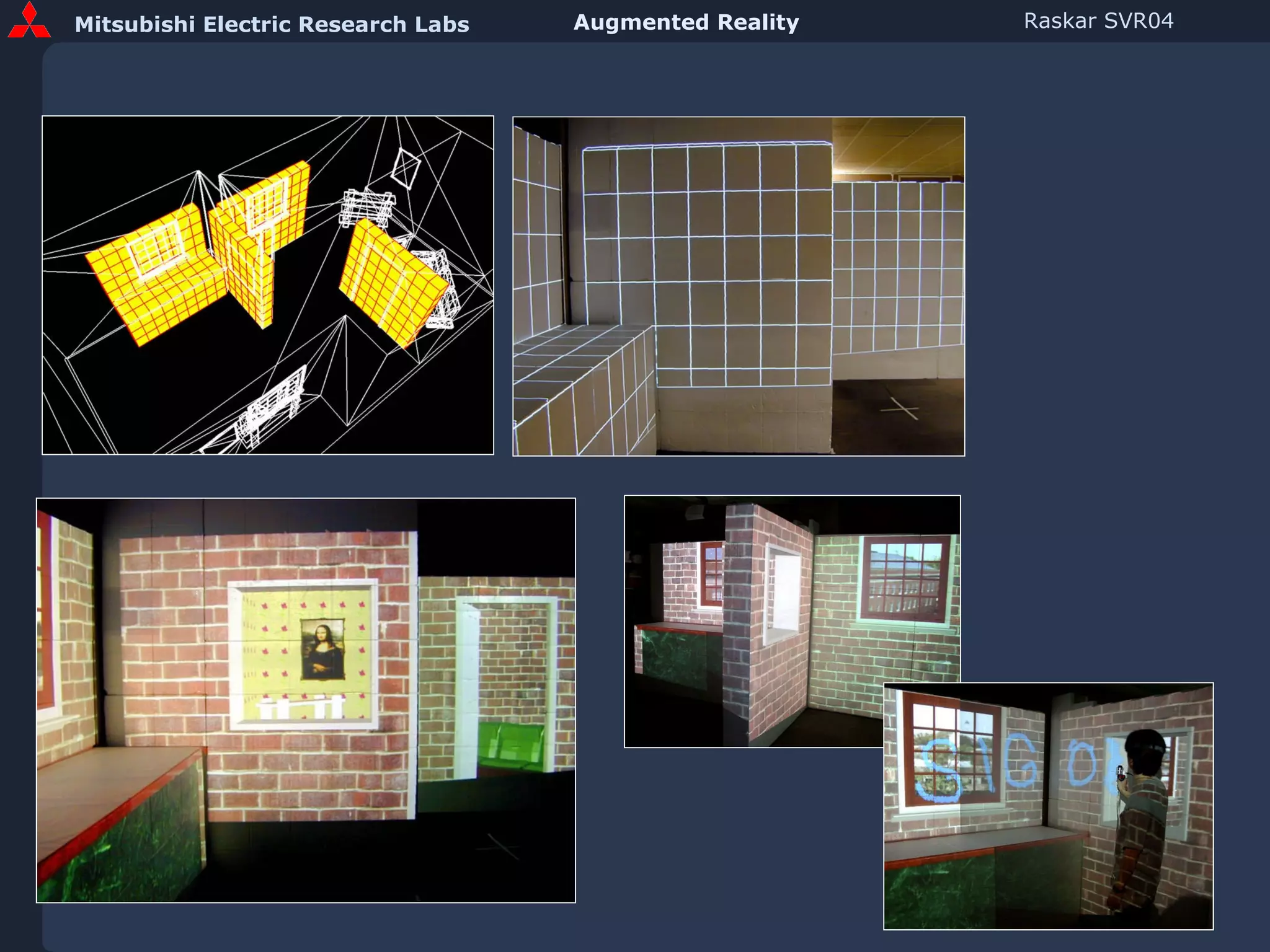
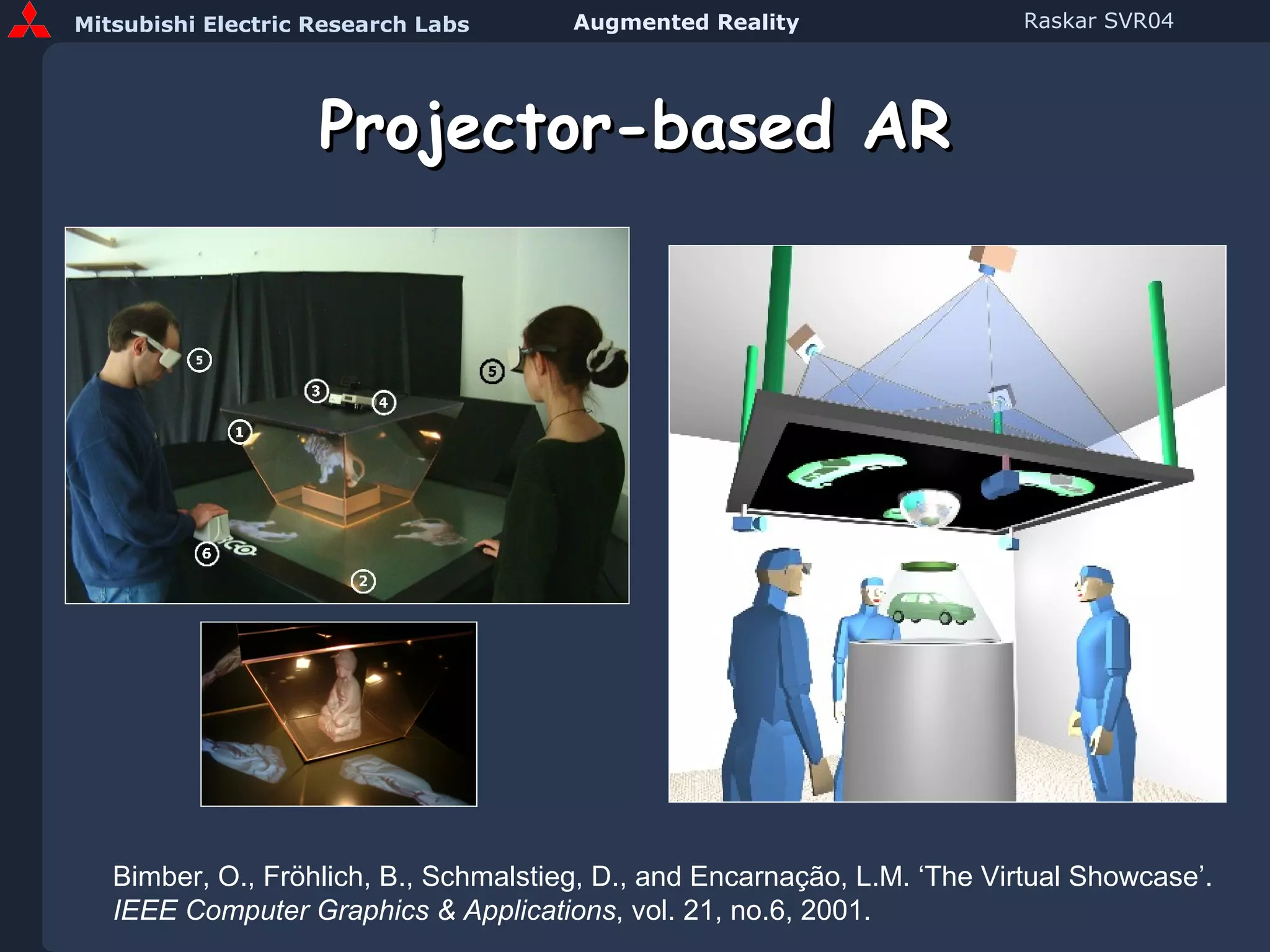
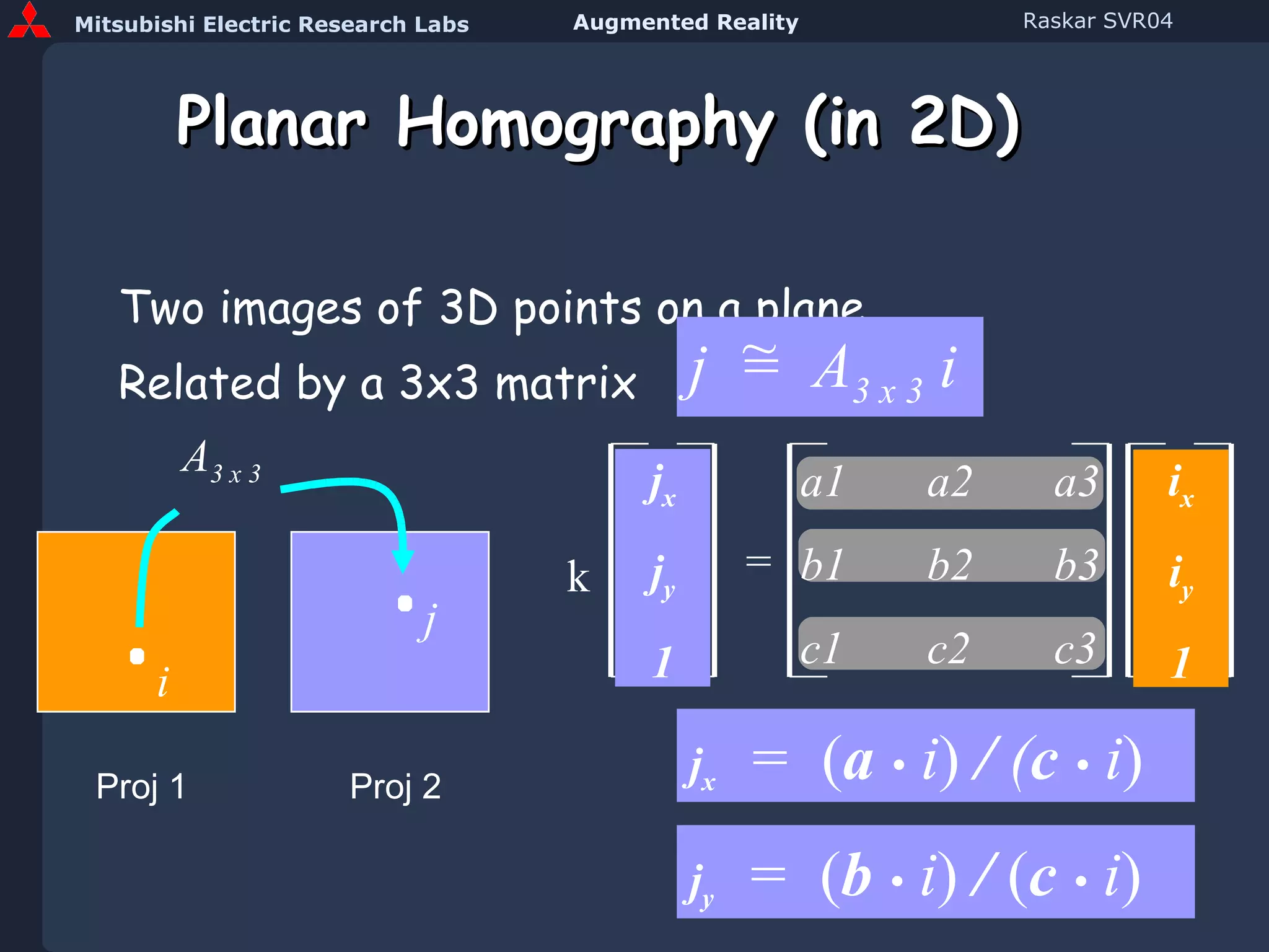
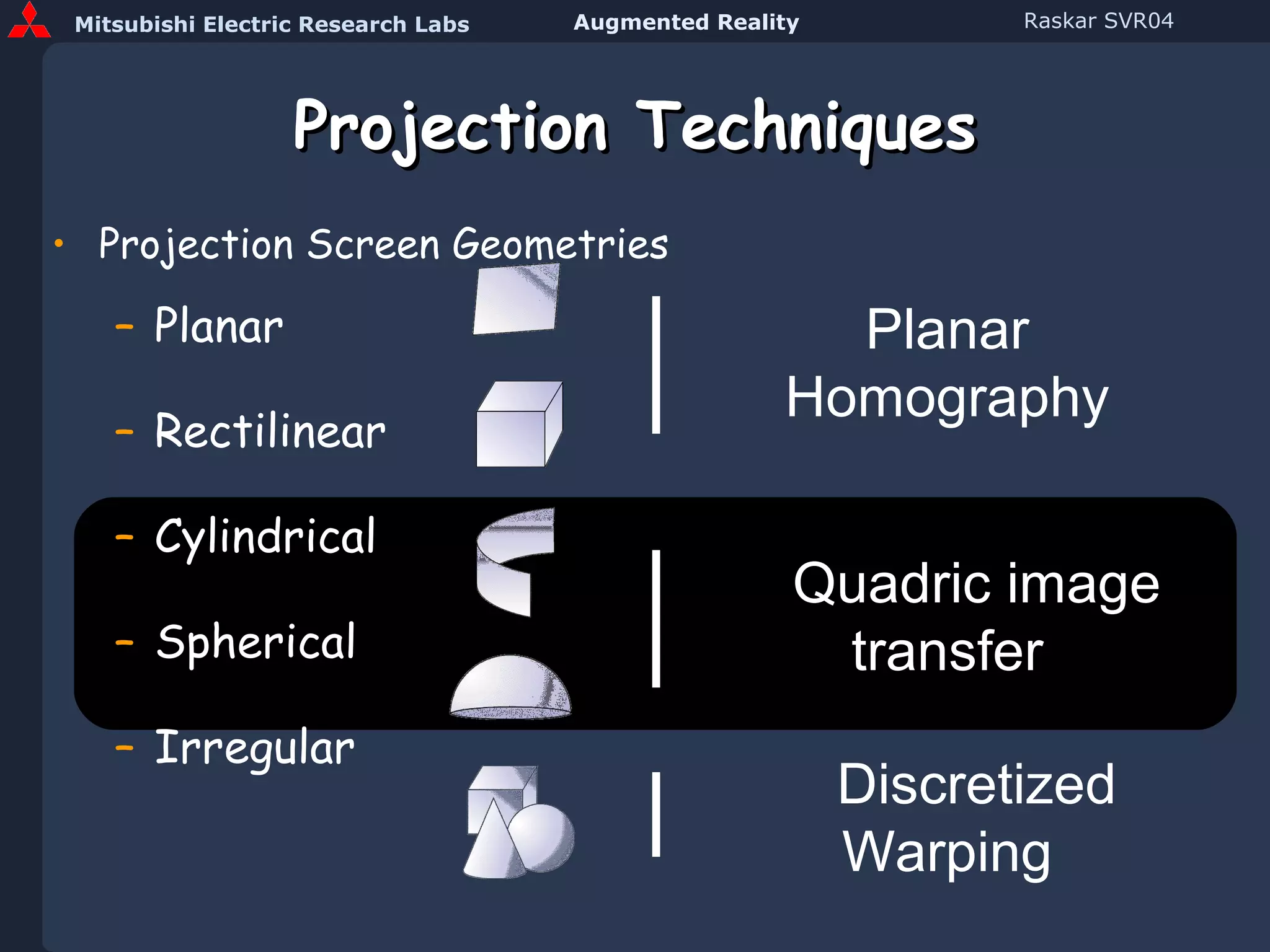
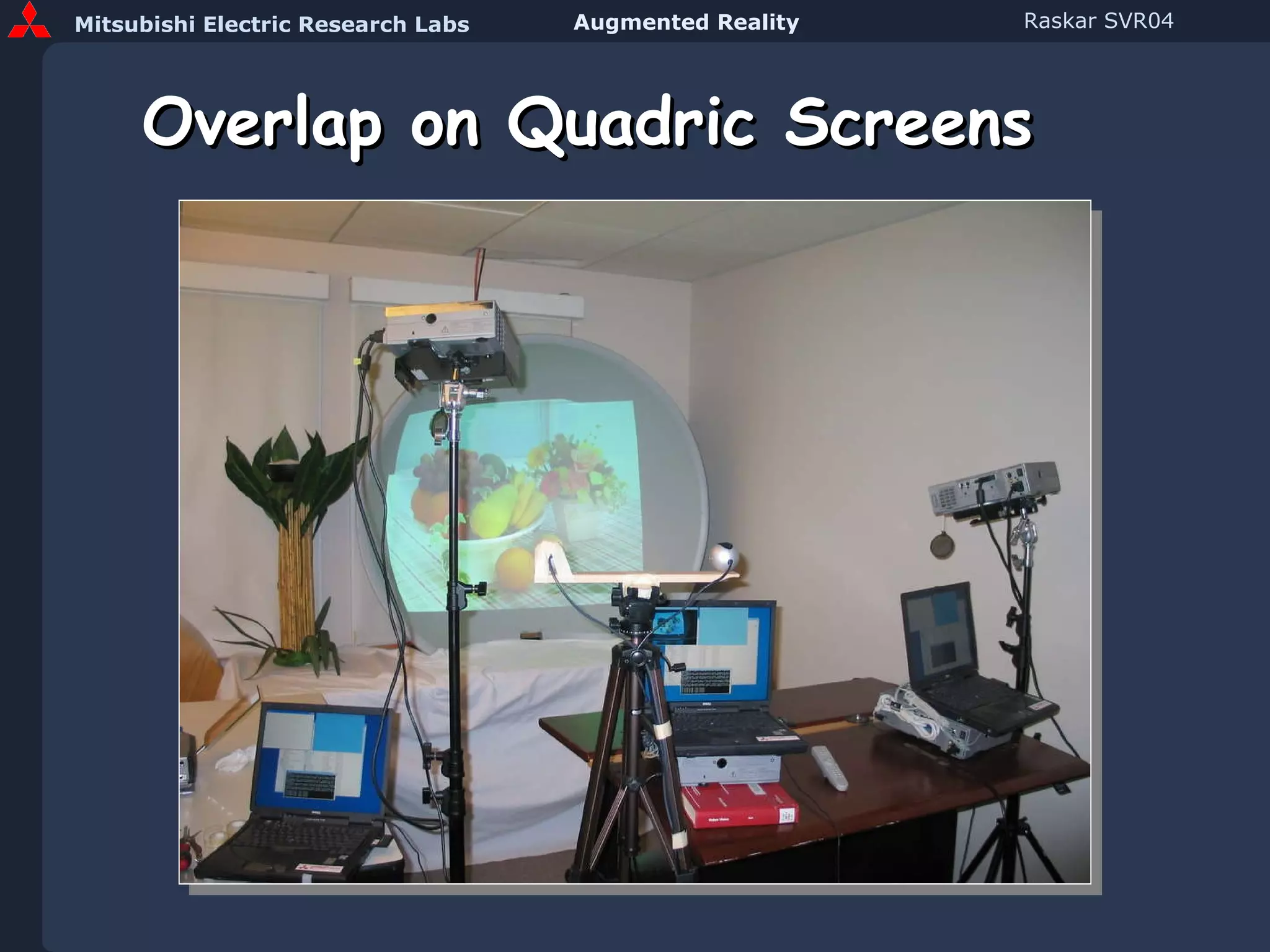
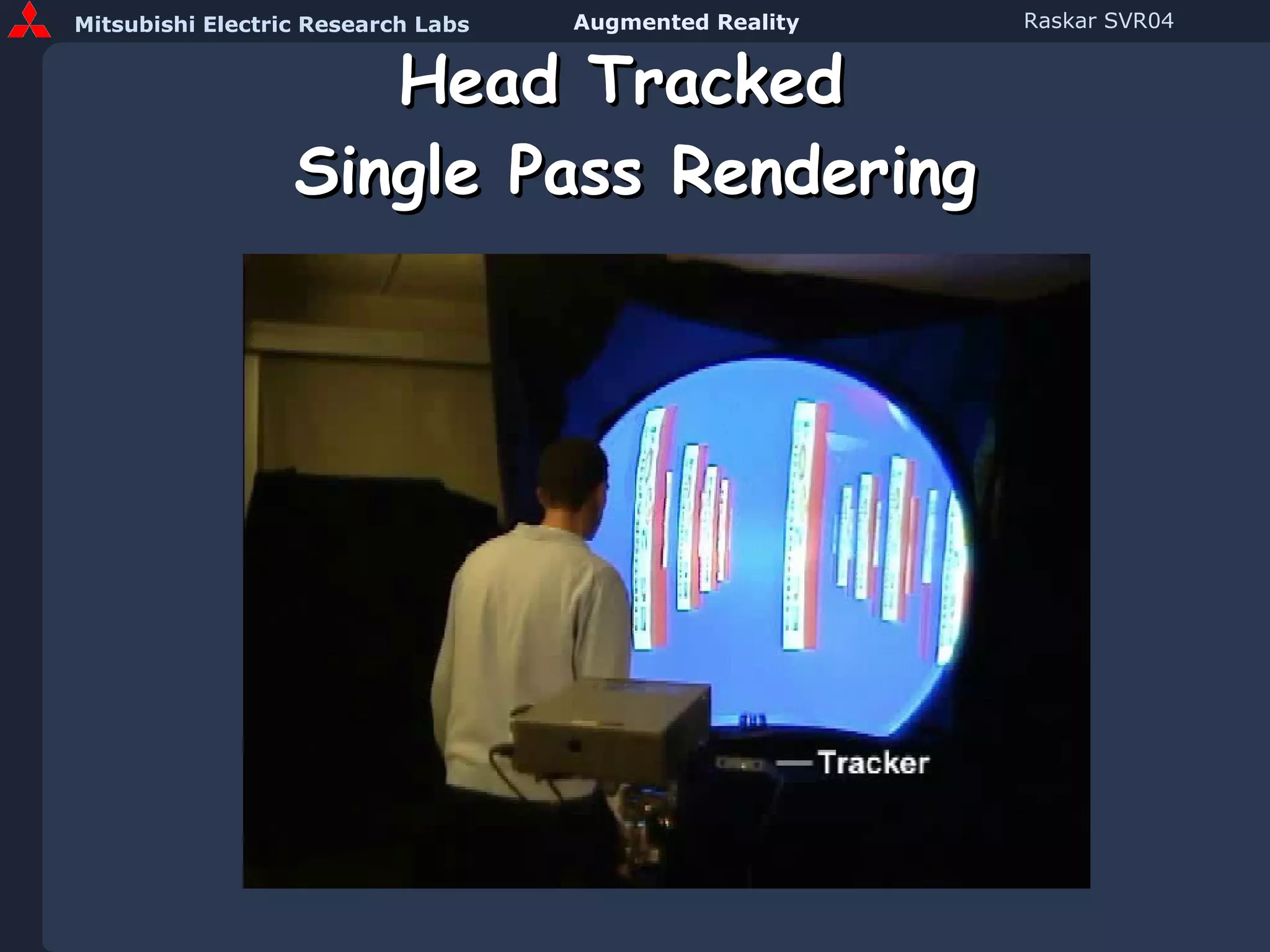
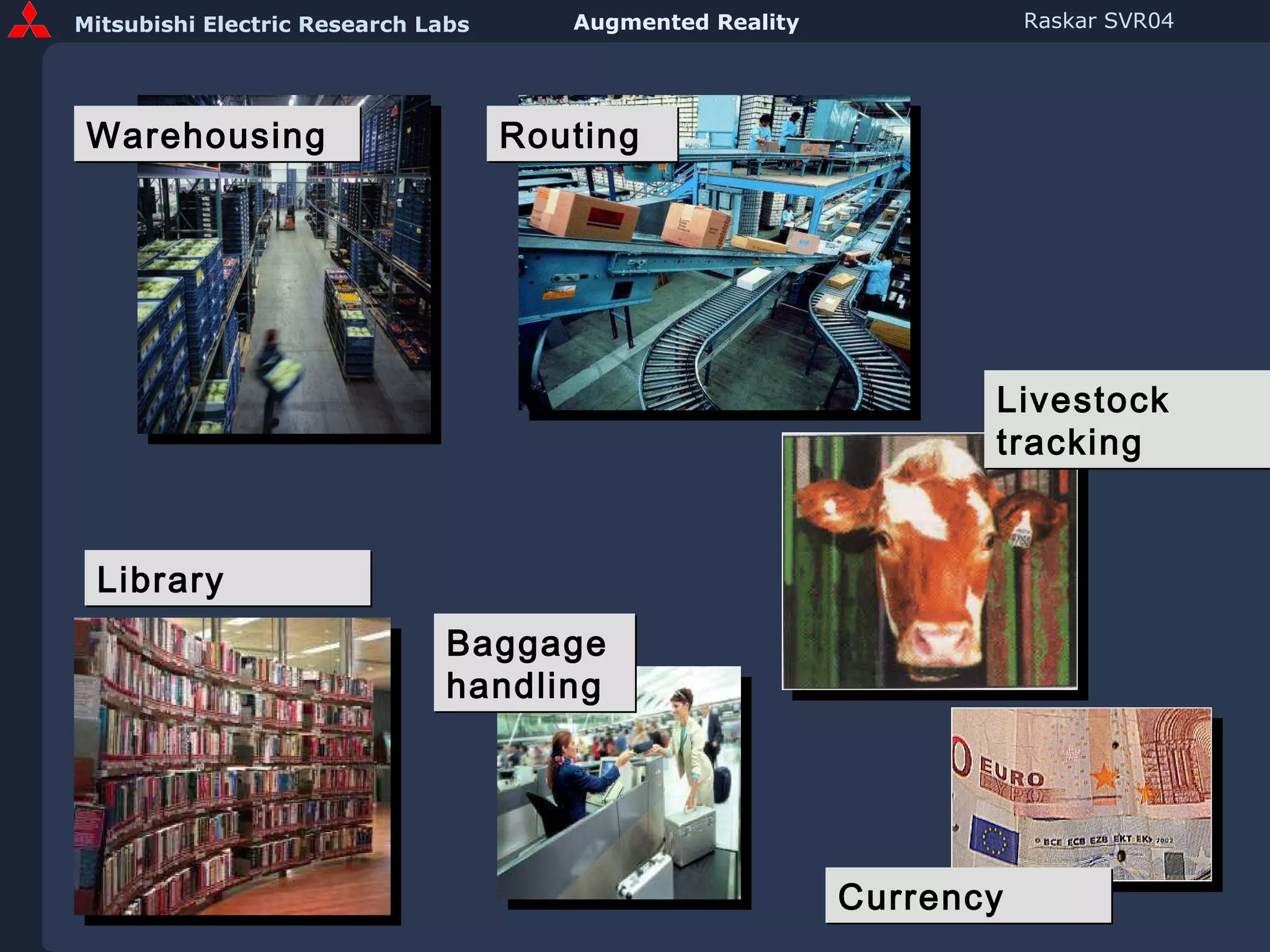
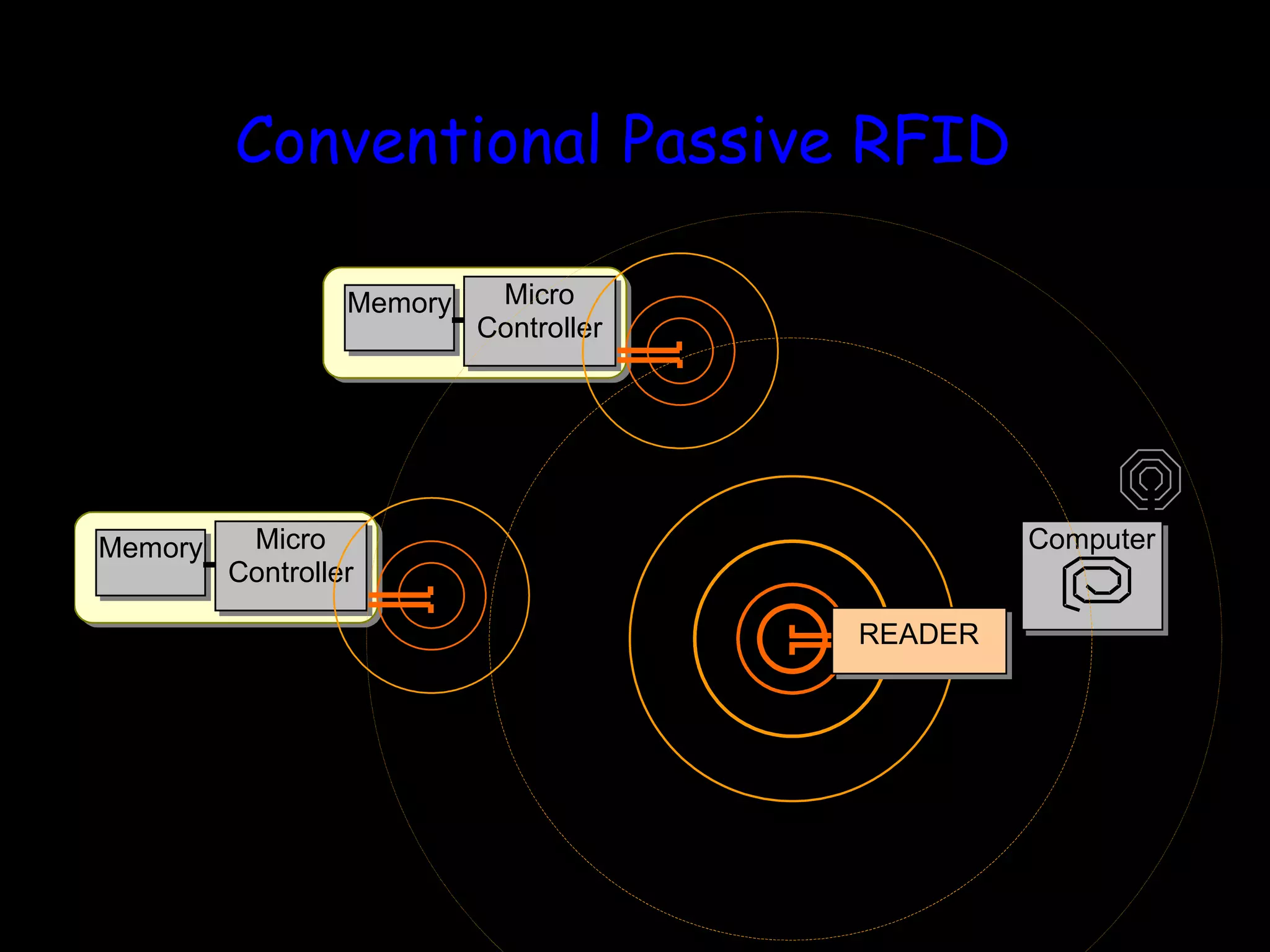
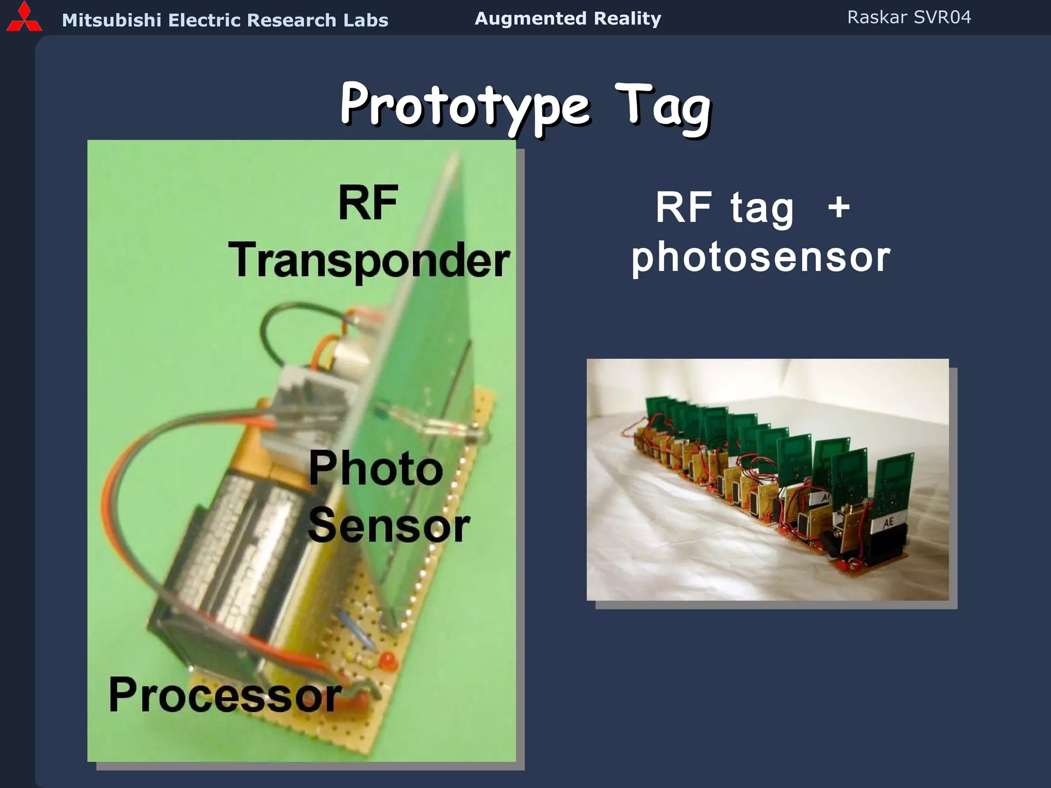
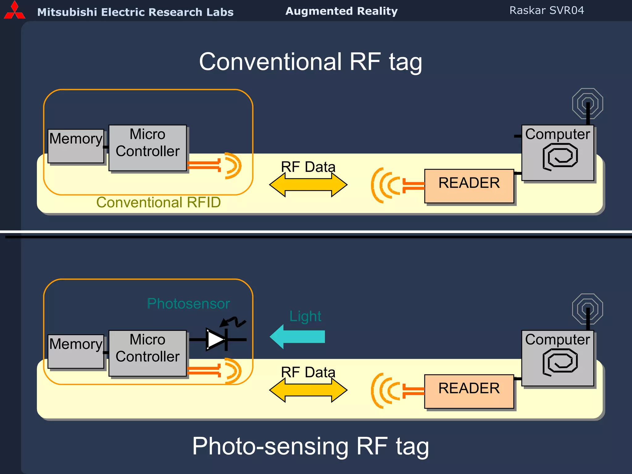
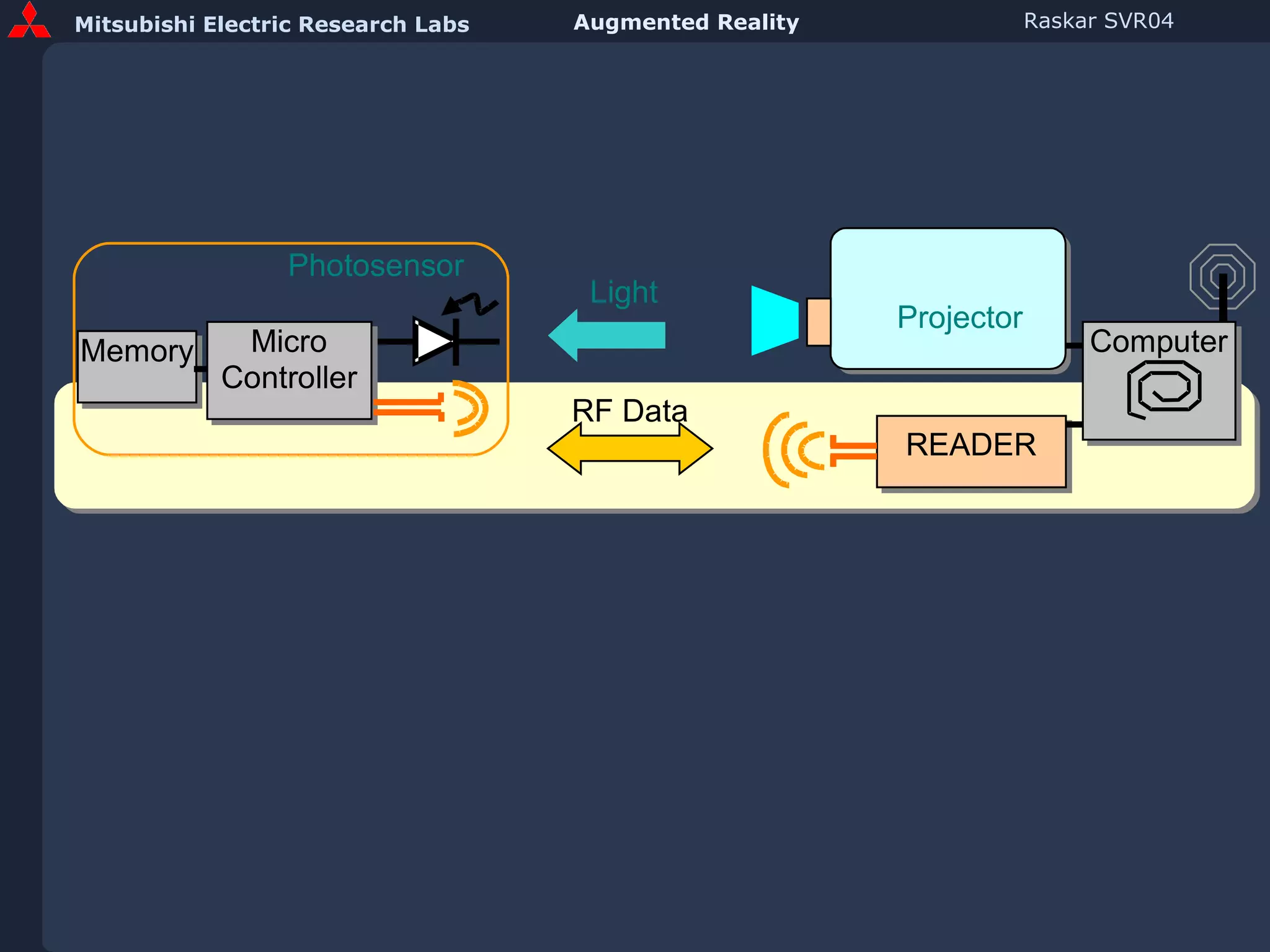
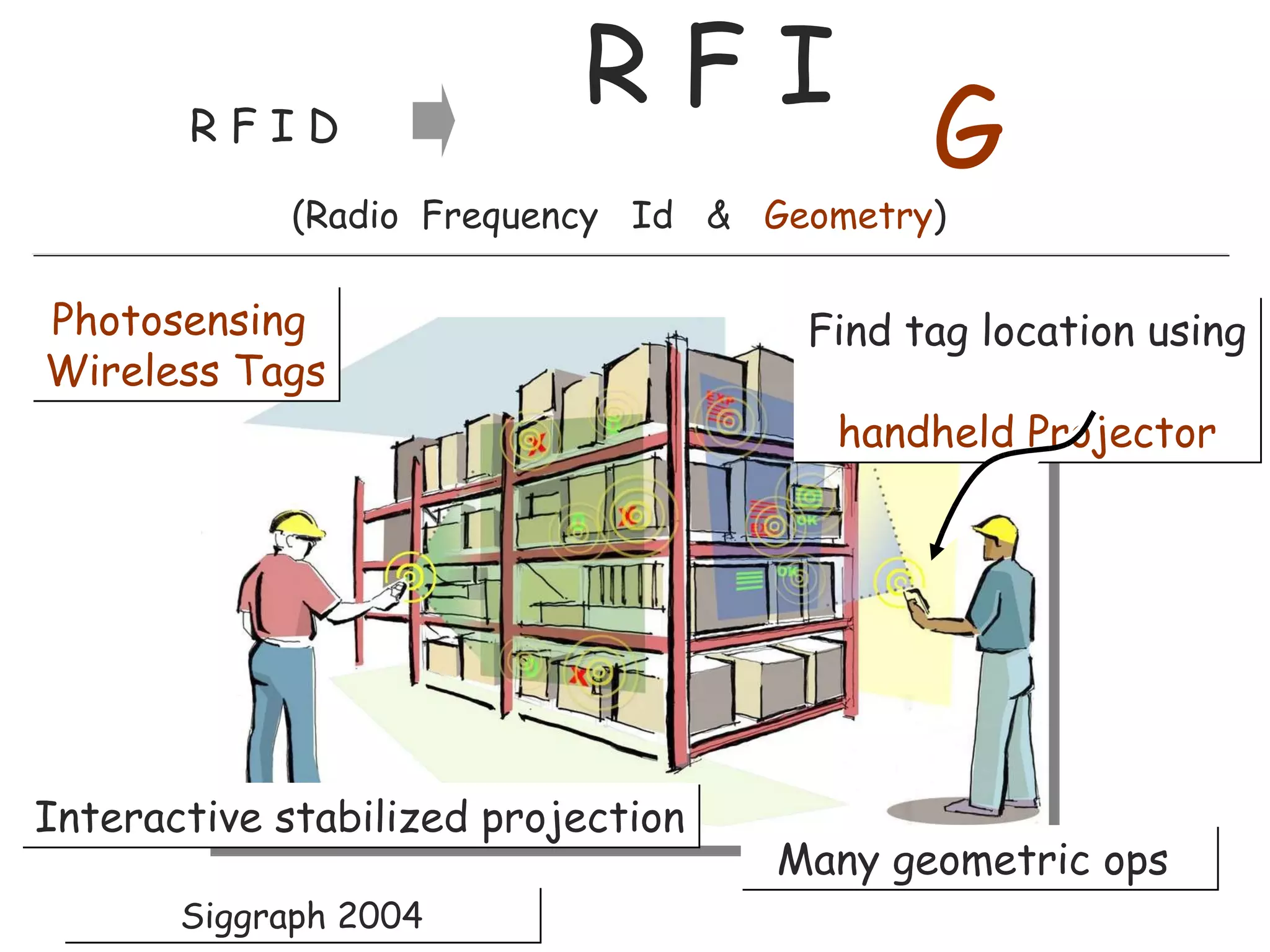
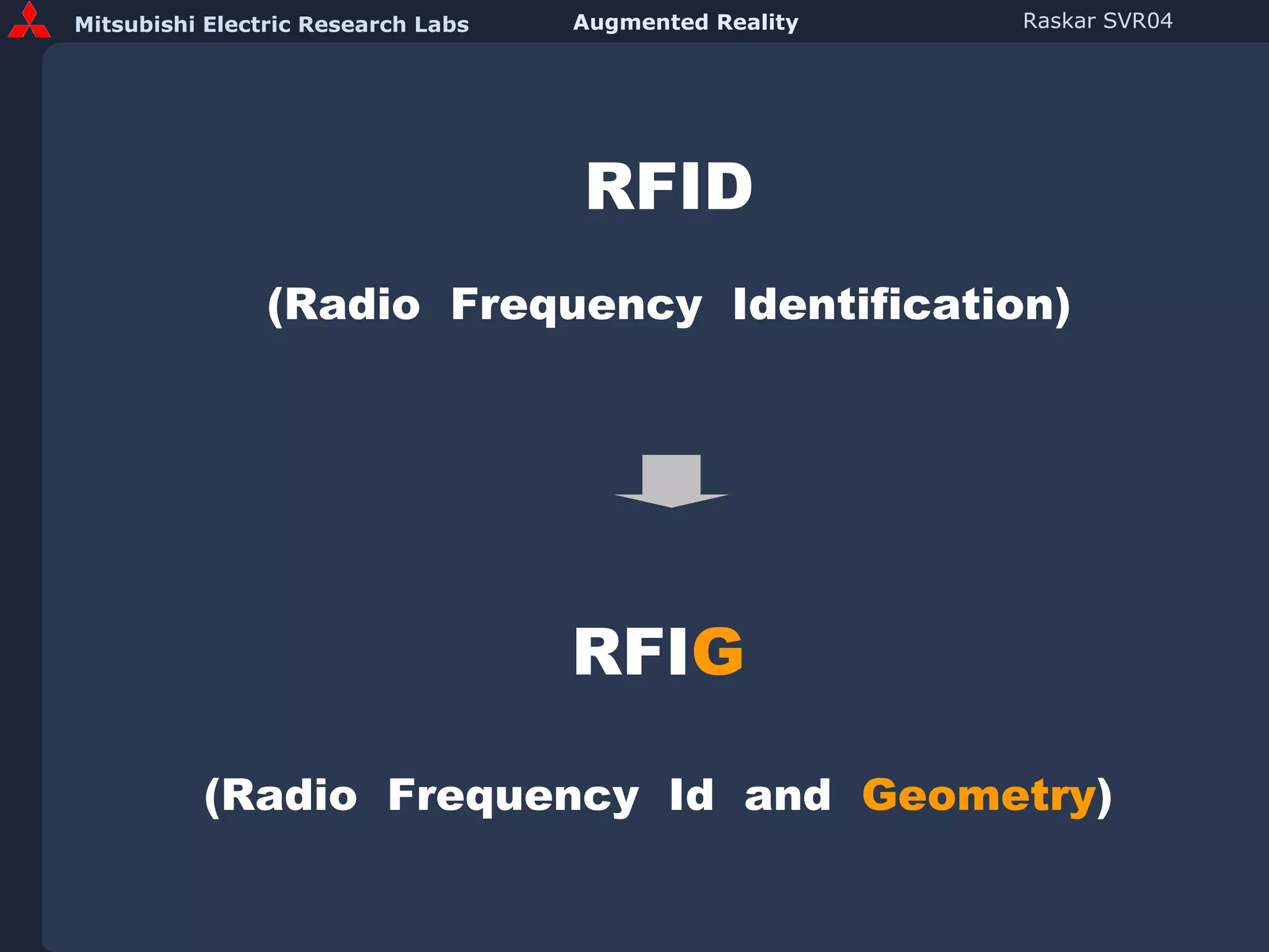
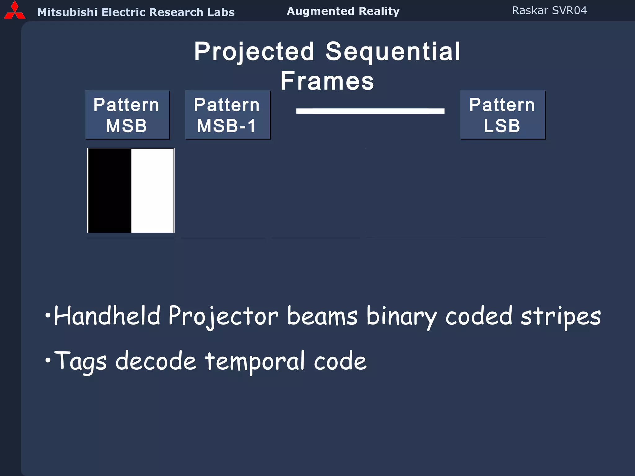
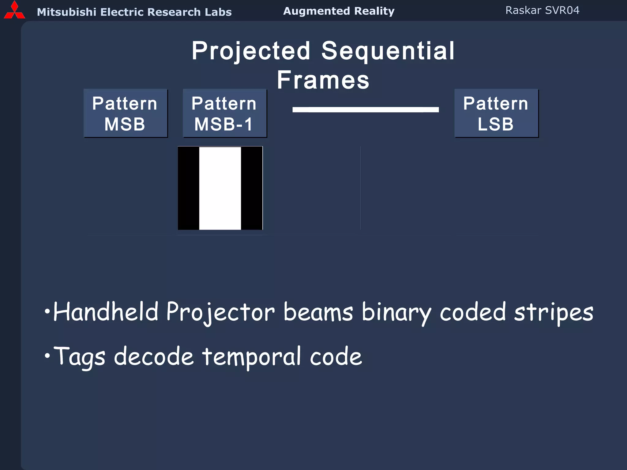
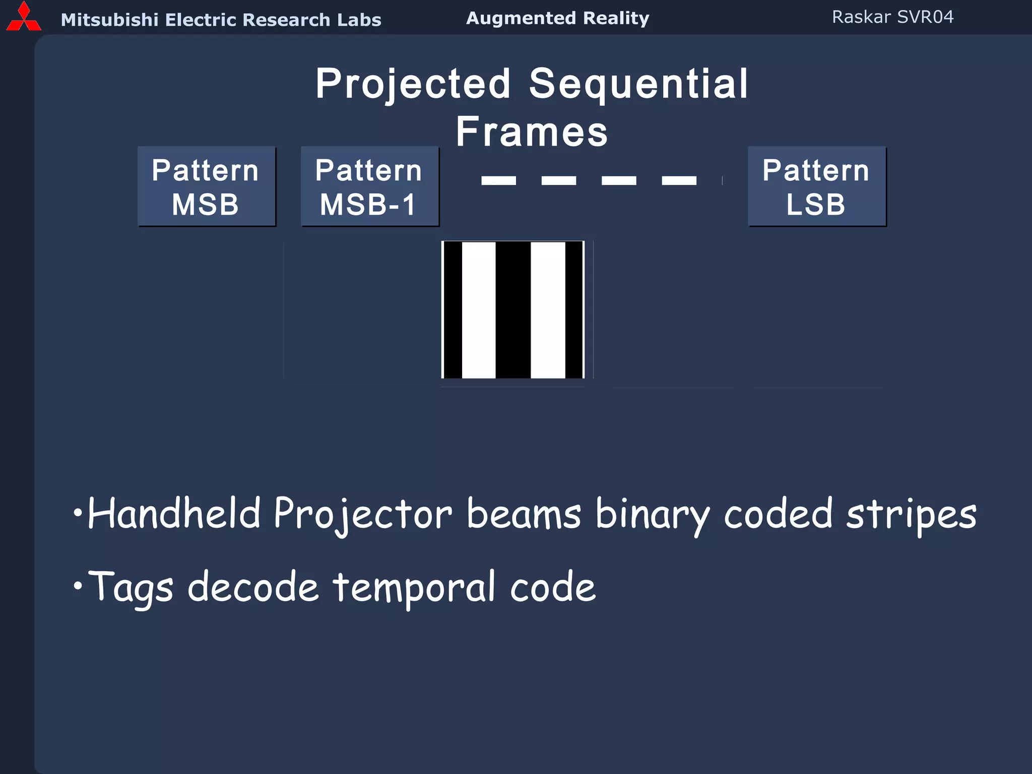
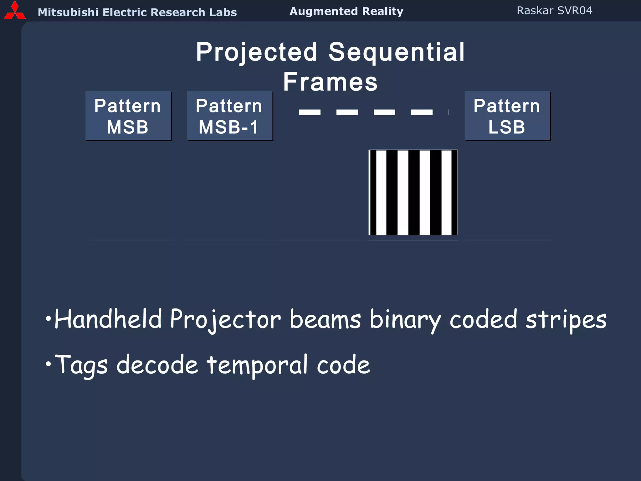
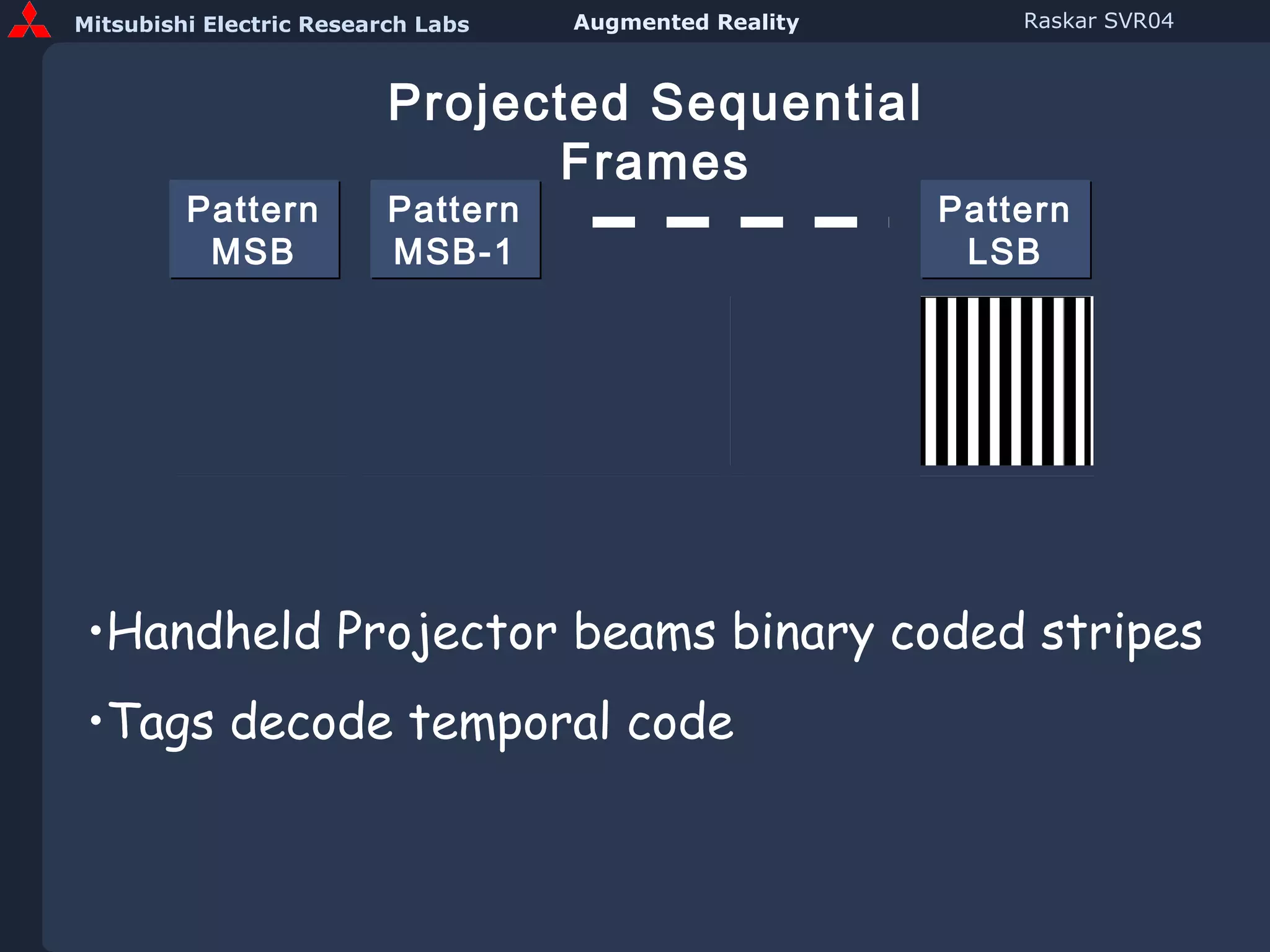
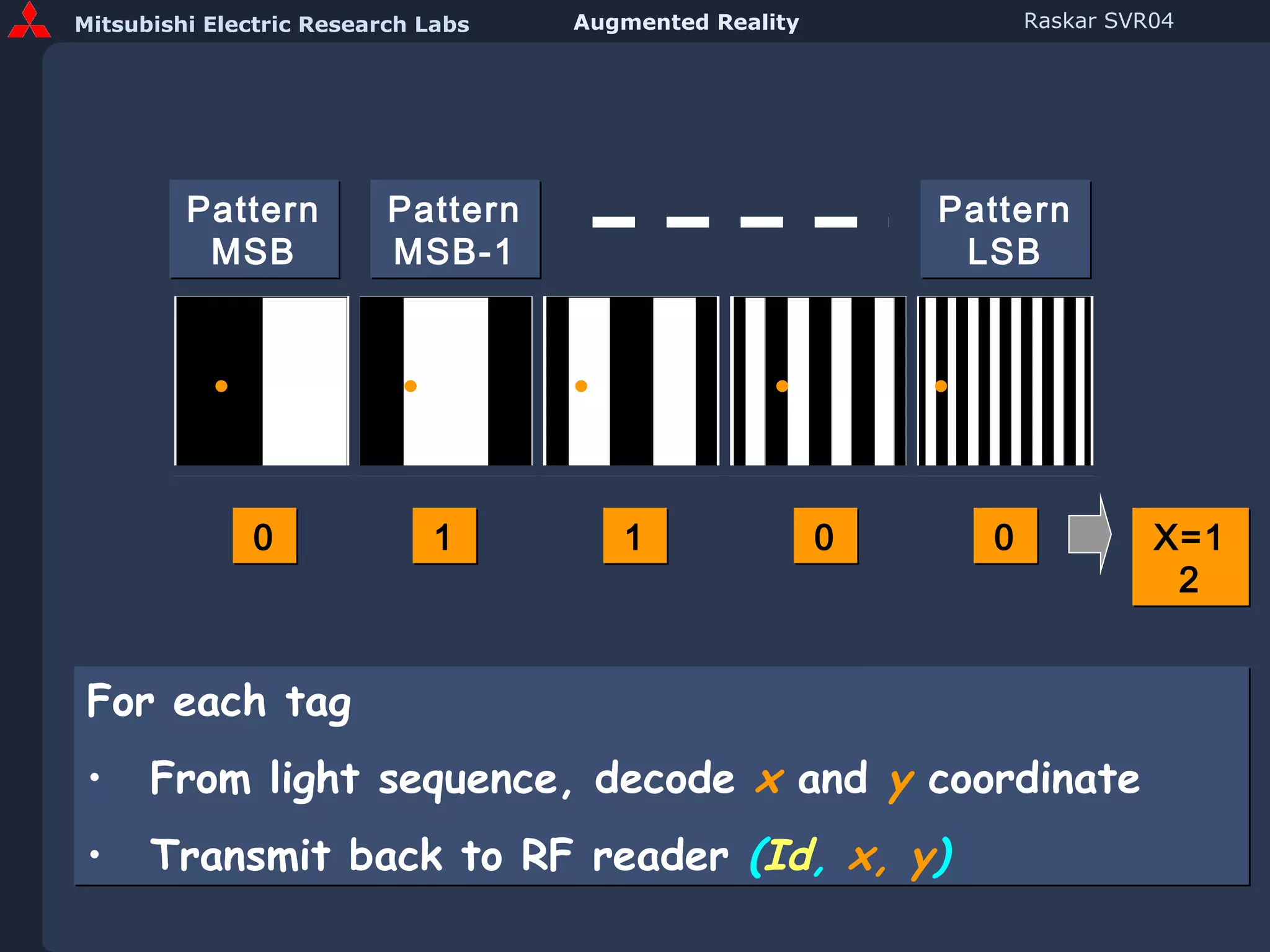
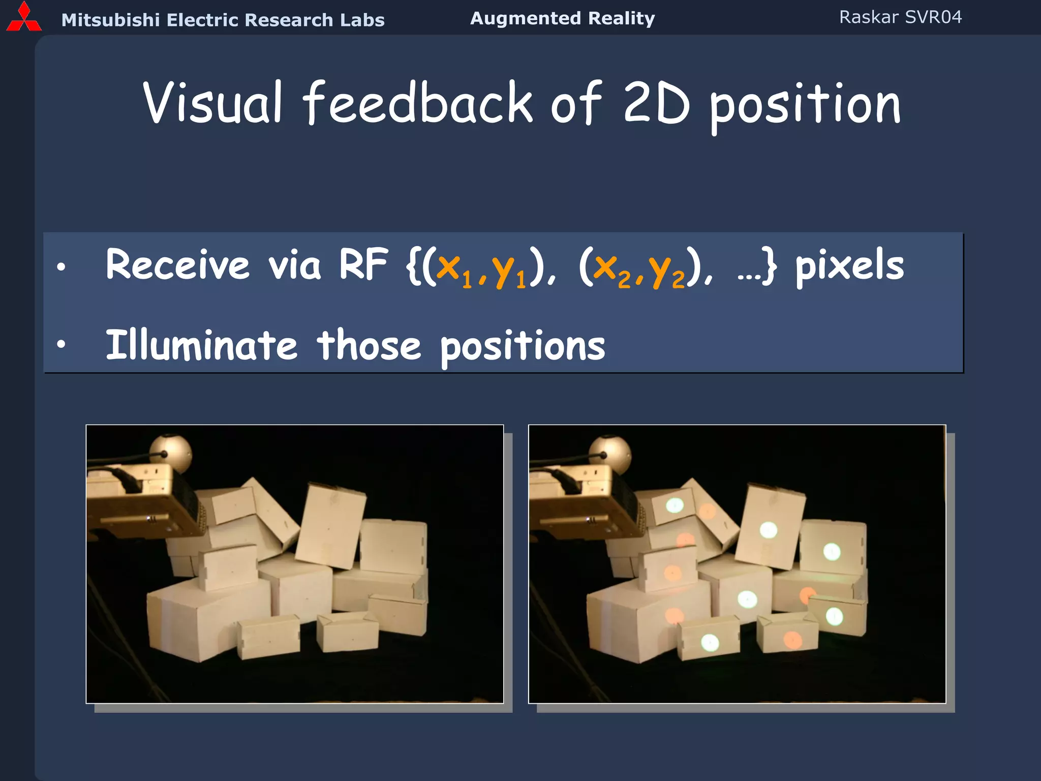
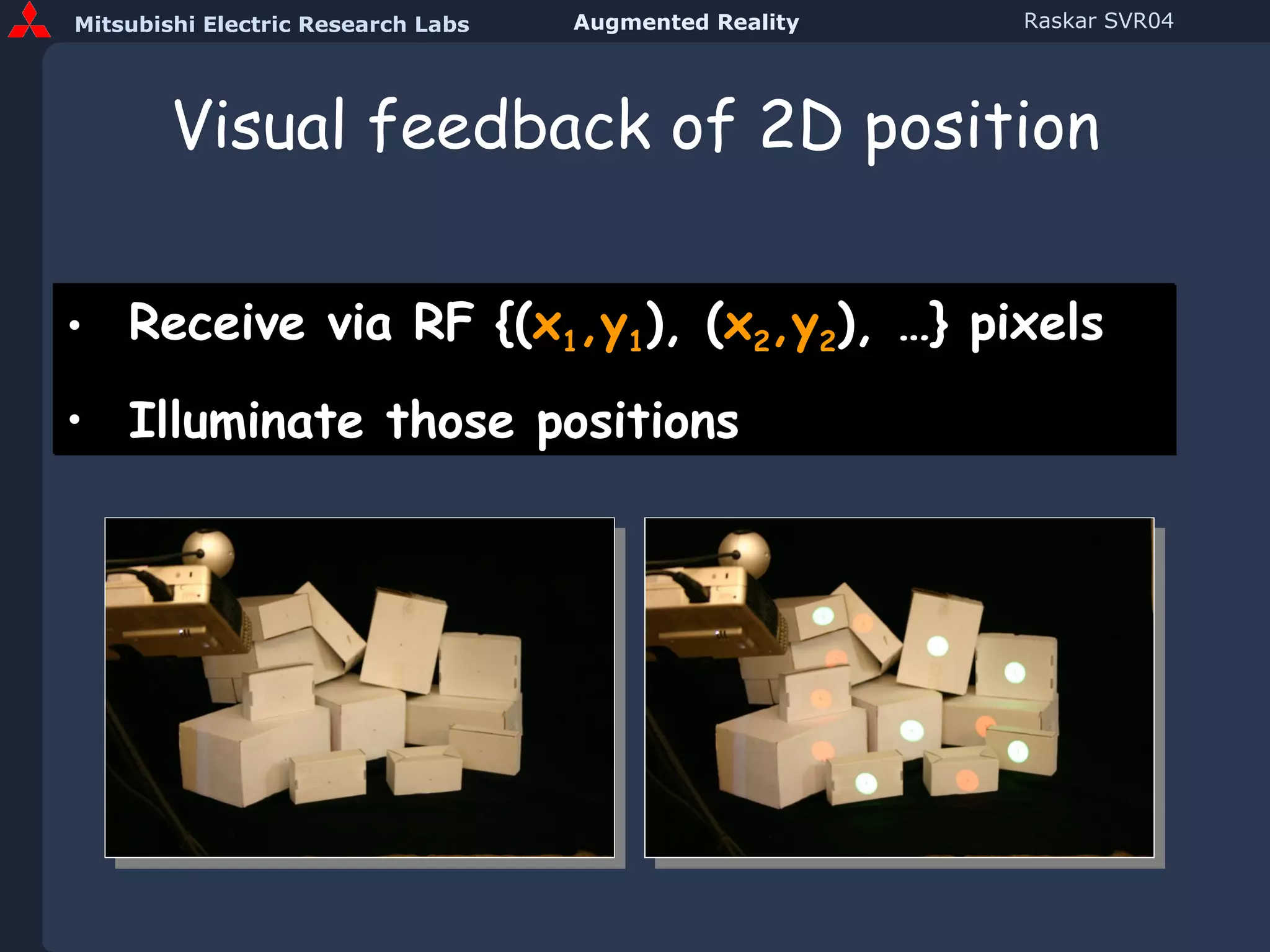
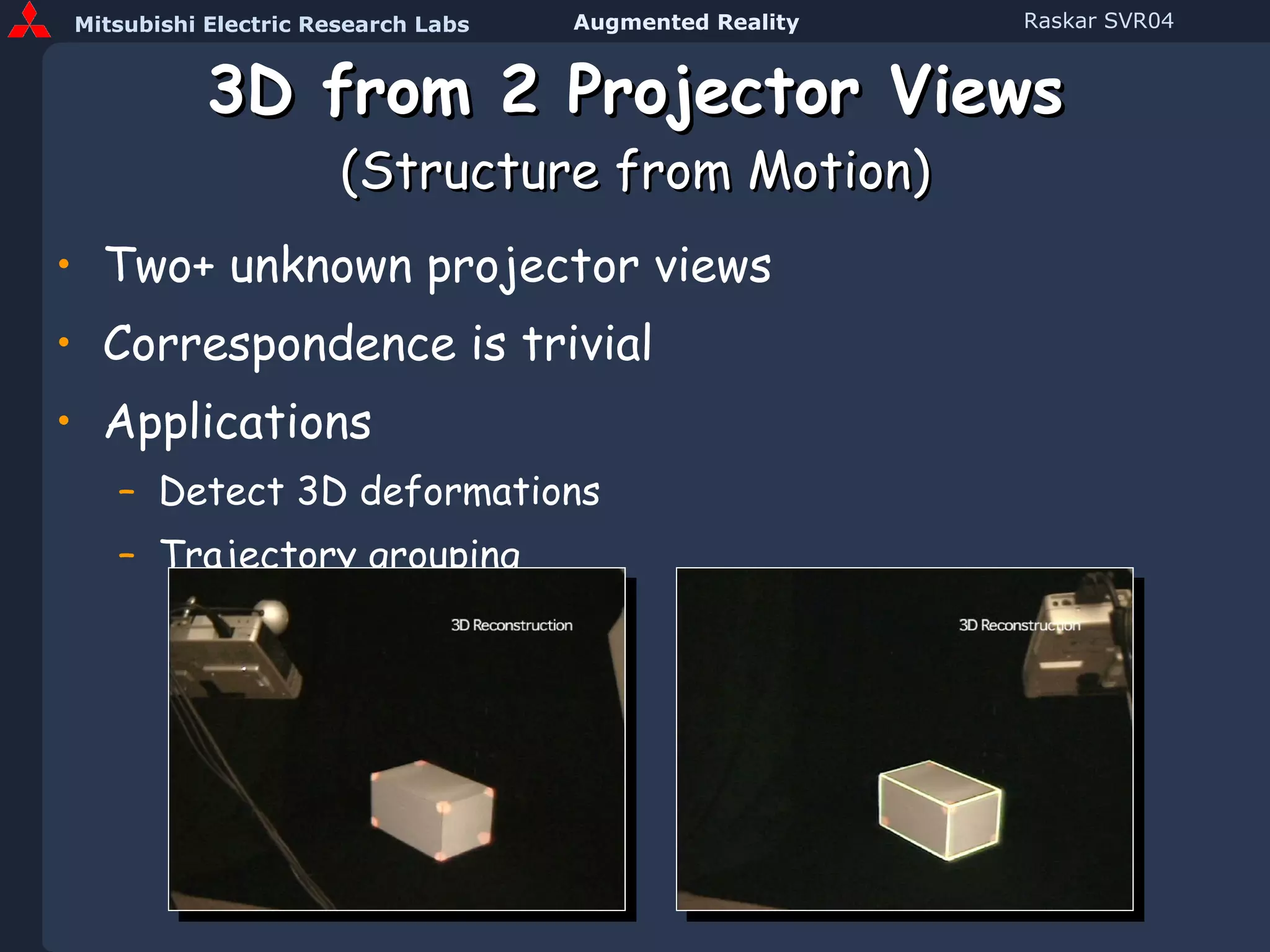
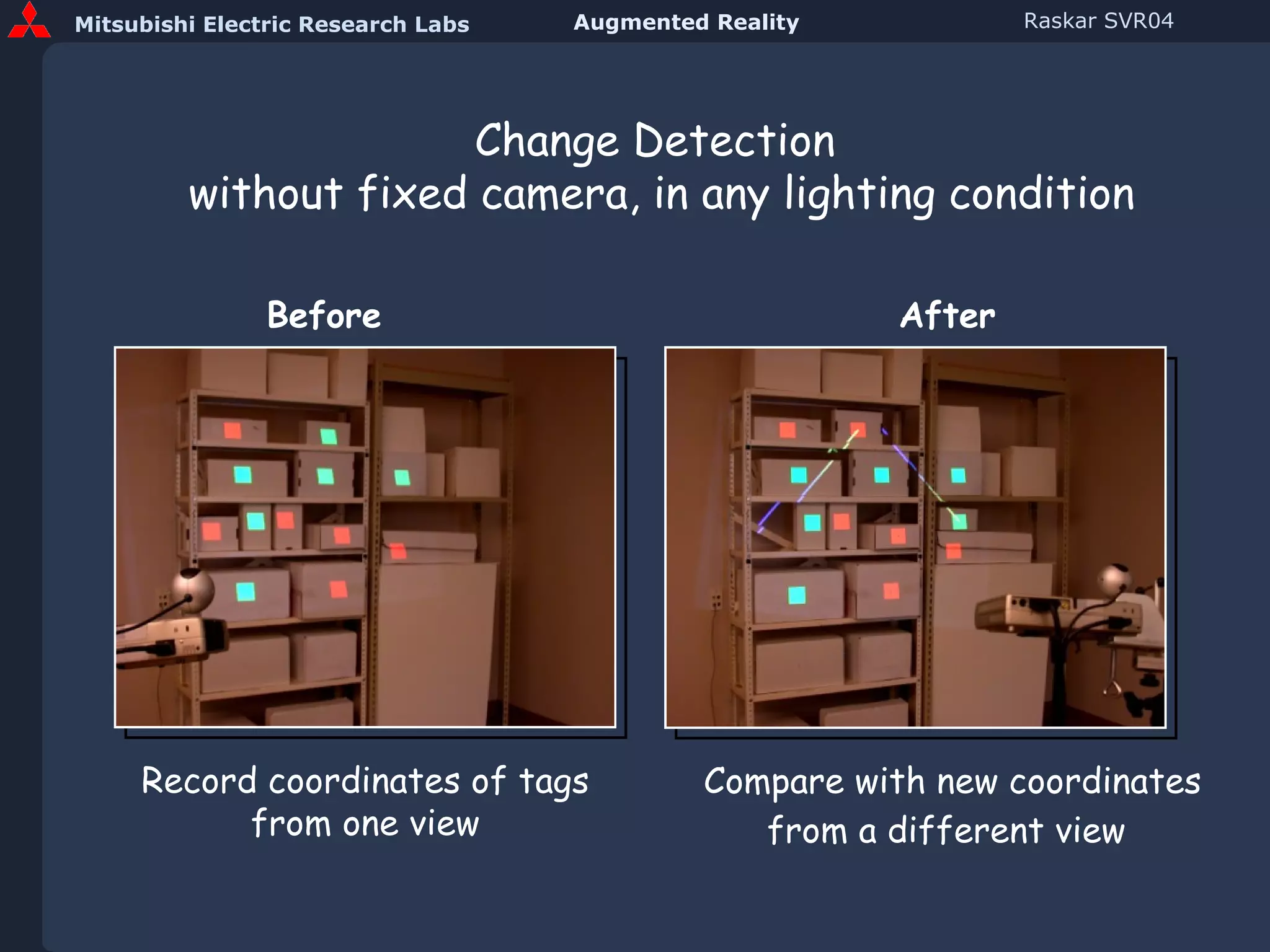
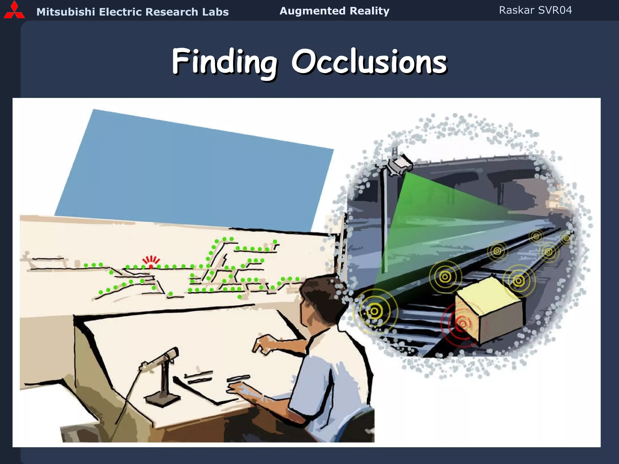
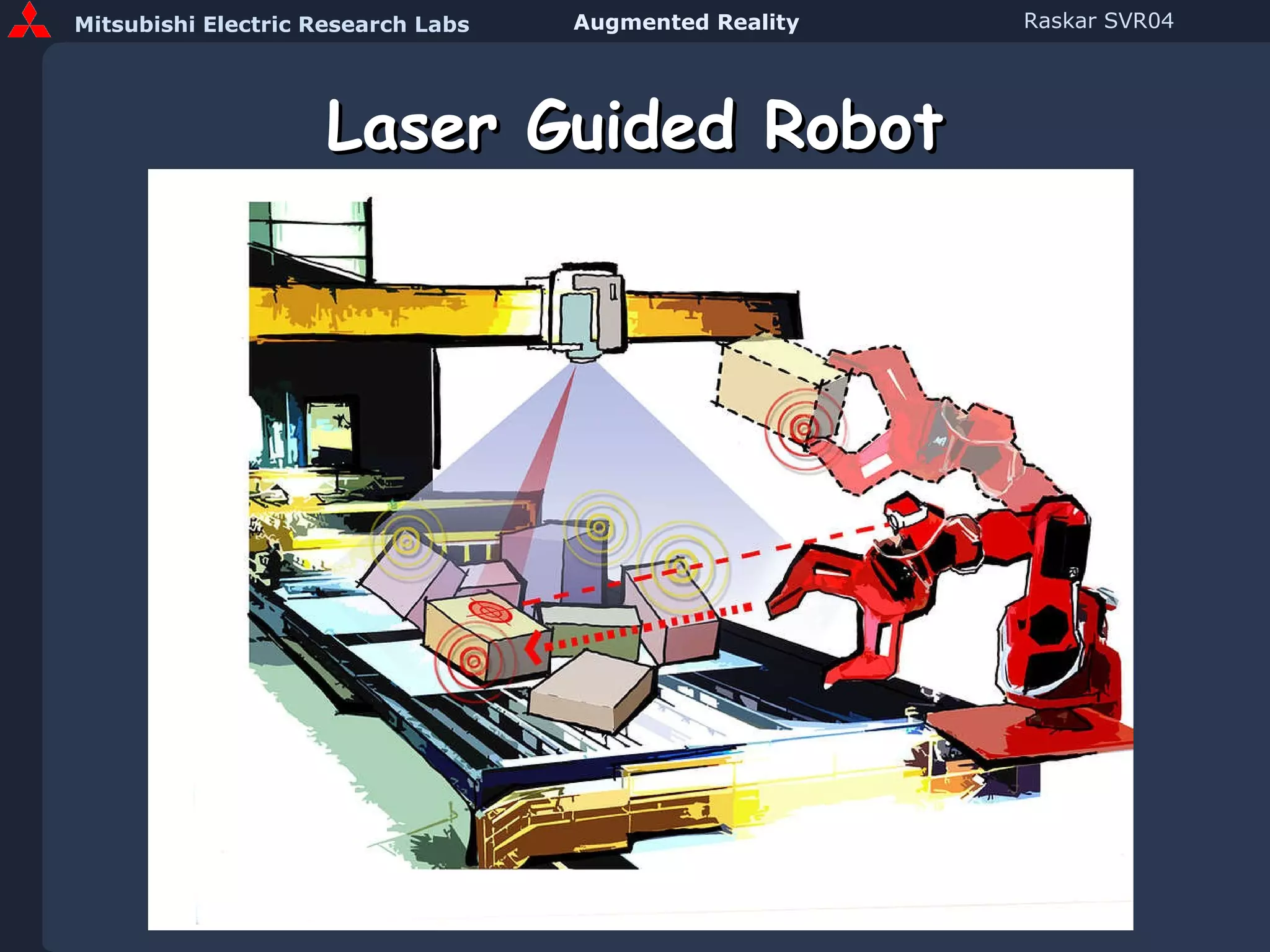
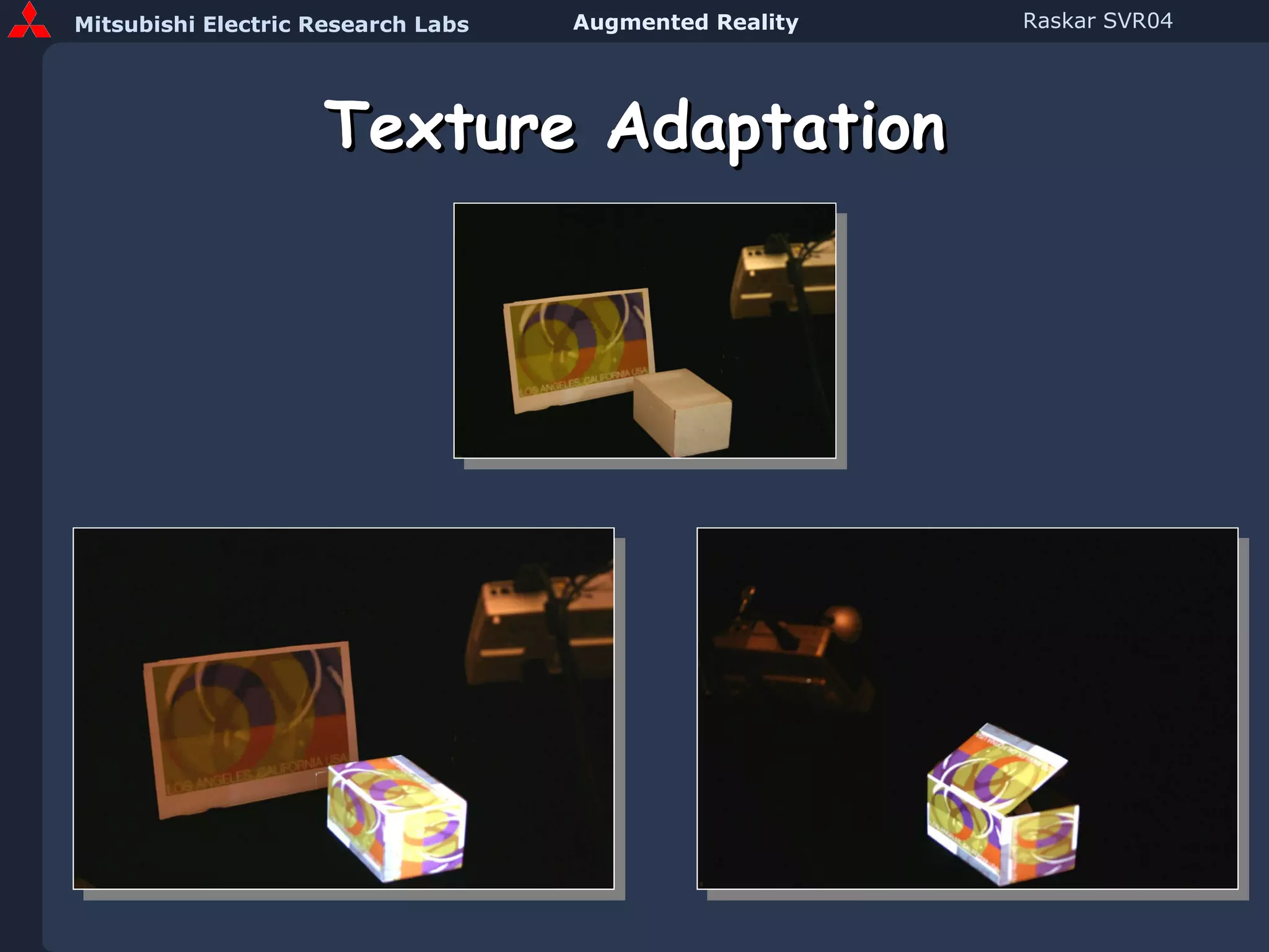
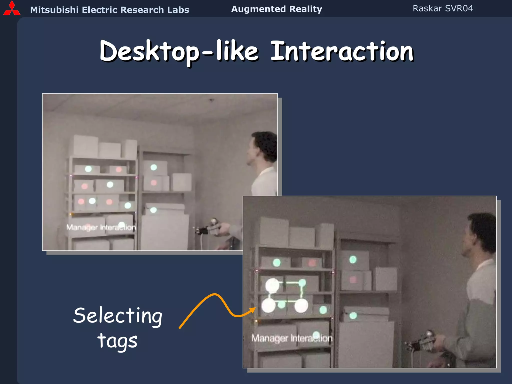
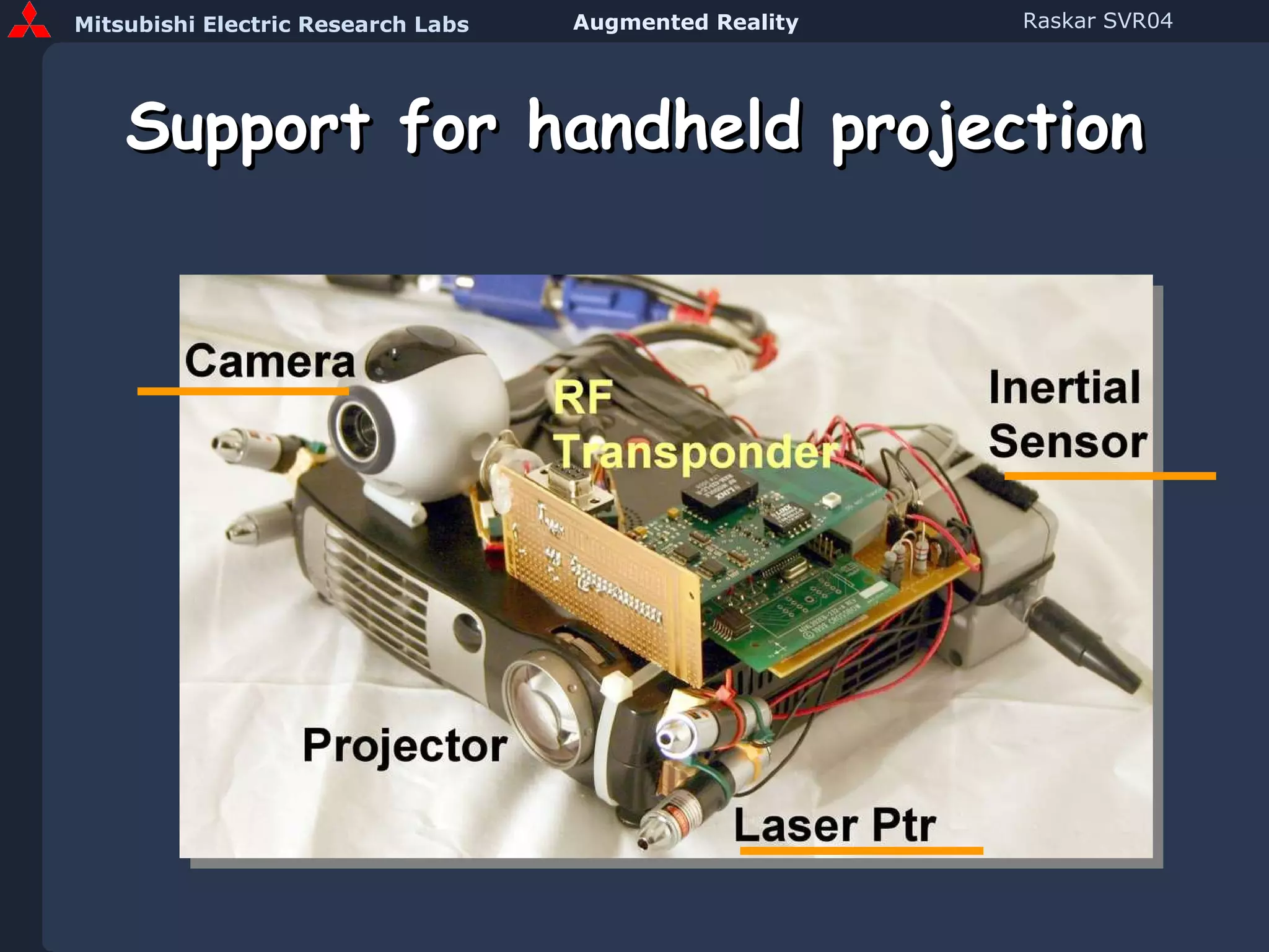
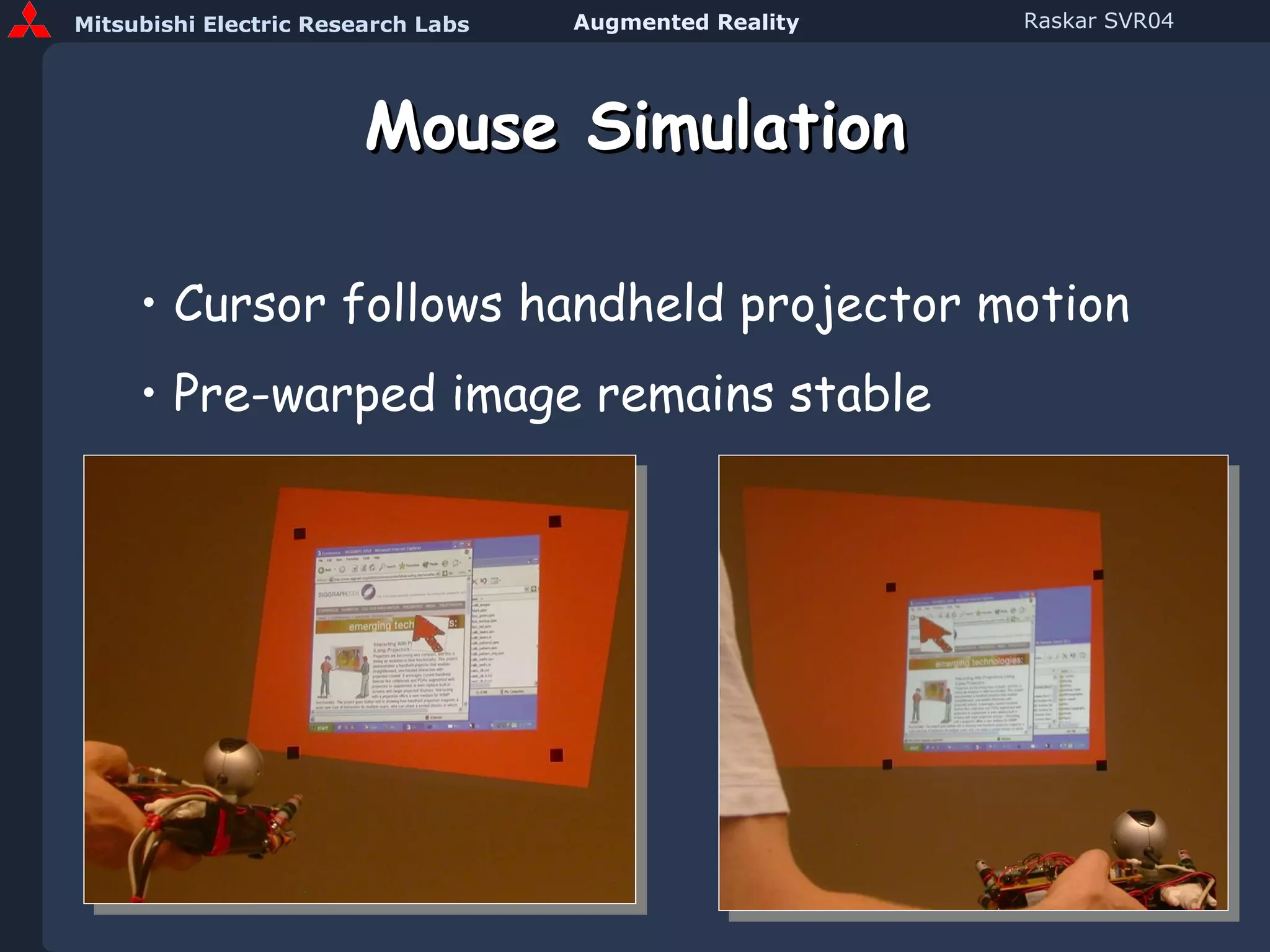
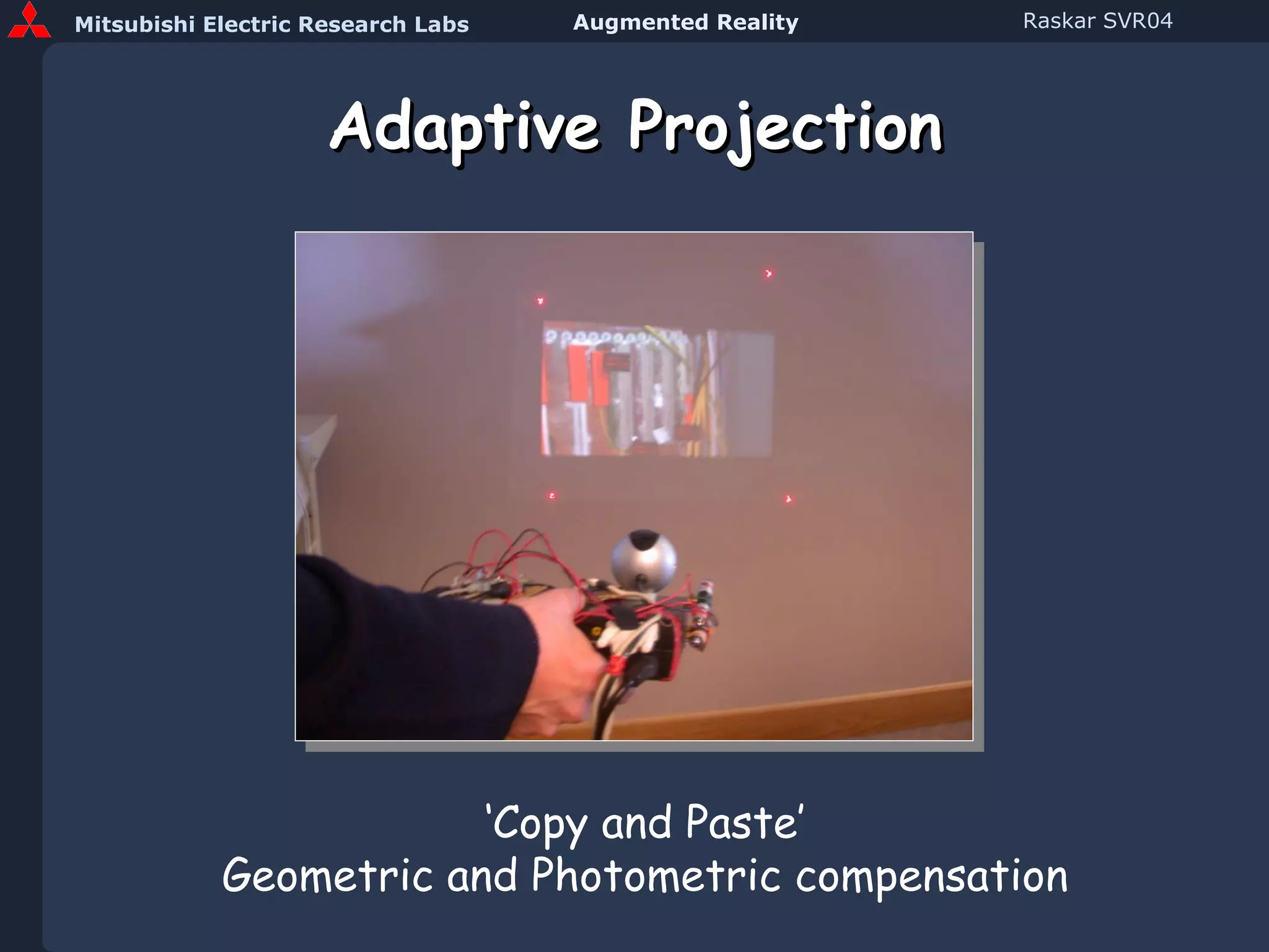
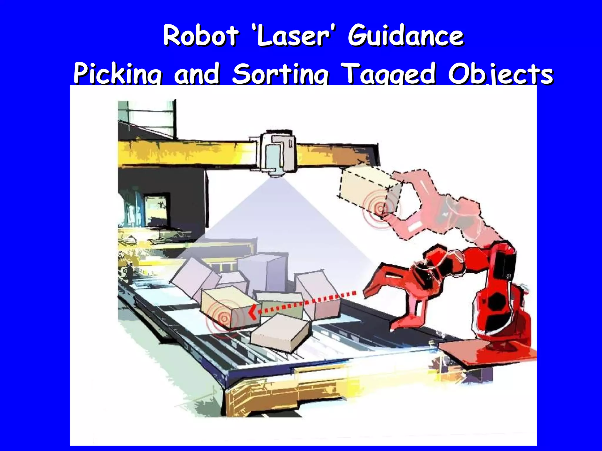
The document discusses spatially augmented reality (SAR) and using projectors to augment real-world objects by projecting virtual images and textures onto them. It describes key challenges in SAR such as calibration, rendering, and handling shadows and reflections. SAR allows augmentation of wide areas with high resolution and avoids issues of body-worn displays. The document also discusses using photosensing RFID tags and a handheld projector to determine tag locations and enable interaction with augmented real-world objects.


![2008 brokerage 03 scalable 3 d models [compatibility mode]](https://cdn.slidesharecdn.com/ss_thumbnails/2008brokerage03-scalable3dmodelscompatibilitymode-100413035231-phpapp01-thumbnail.jpg?width=640&height=640&fit=bounds)


![Vibe Coding vs. Spec-Driven Development [Free Meetup]](https://cdn.slidesharecdn.com/ss_thumbnails/vibecodingvsspecdrivendevelopment-251209105622-43f455e7-thumbnail.jpg?width=640&height=640&fit=bounds)


