This document describes a project that implemented simultaneous localization and mapping (SLAM) using a Pioneer 3-DX robot equipped with a SICK laser range finder and wheel encoders. The robot was able to navigate autonomously indoors and create a map of its environment in real-time using an Extended Kalman Filter (EKF) based SLAM algorithm. The EKF estimates both the robot's state and the locations of environmental features observed by the laser range finder based on odometry from the wheel encoders and laser range measurements to features. The project demonstrated successful indoor navigation and mapping of a simple route using this SLAM system.
LiDAR in the Adverse Weather: Dust, Snow, Rain and Fog (2)Yu Huang
Canadian Adverse Driving Conditions Dataset, 2020, 2
Deep multimodal sensor fusion in unseen adverse weather, 2020, 8
RADIATE: A Radar Dataset for Automotive Perception in Bad Weather, 2021, 4
Lidar Light Scattering Augmentation (LISA): Physics-based Simulation of Adverse Weather Conditions for 3D Object Detection, 2021, 7
Fog Simulation on Real LiDAR Point Clouds for 3D Object Detection in Adverse Weather, 2021, 8
DSOR: A Scalable Statistical Filter for Removing Falling Snow from LiDAR Point Clouds in Severe Winter Weather, 2021, 9
2019年6月13日、SSII2019 Organized Session: Multimodal 4D sensing。エンドユーザー向け SLAM 技術の現在。登壇者:武笠 知幸(Research Scientist, Rakuten Institute of Technology)
https://confit.atlas.jp/guide/event/ssii2019/static/organized#OS2
SIGGRAPH 2014 Course on Computational Cameras and Displays (part 3)Matthew O'Toole
Recent advances in both computational photography and displays have given rise to a new generation of computational devices. Computational cameras and displays provide a visual experience that goes beyond the capabilities of traditional systems by adding computational power to optics, lights, and sensors. These devices are breaking new ground in the consumer market, including lightfield cameras that redefine our understanding of pictures (Lytro), displays for visualizing 3D/4D content without special eyewear (Nintendo 3DS), motion-sensing devices that use light coded in space or time to detect motion and position (Kinect, Leap Motion), and a movement toward ubiquitous computing with wearable cameras and displays (Google Glass).
This short (1.5 hour) course serves as an introduction to the key ideas and an overview of the latest work in computational cameras, displays, and light transport.
Abstract In this paper, localization of the robot is achieved by considering two Global Positioning Systems (GPS) or DGPS. Differential Global Positioning System (DGPS) is interfaced with MBED with the help of Zigbee protocol. For accurate localization of mobile robot DGPS is preferred. Filters are used to remove the erroneous noise from the data obtained from GPS. Low pass IIR filter for DGPS is realized. The project work discusses each of these approaches for localization in Outdoor environment. The above algorithm is implemented on MBED Platform. Simulation results are extracted using Matlab. Keywords—localization, Outdoor environment, Low pass IIR filter, DGPS, MBED
A Real-Time Implementation of Moving Object Action Recognition System Based o...ijeei-iaes
This paper proposes a PixelStreams-based FPGA implementation of a real-time system that can detect and recognize human activity using Handel-C. In the first part of our work, we propose a GUI programmed using Visual C++ to facilitate the implementation for novice users. Using this GUI, the user can program/erase the FPGA or change the parameters of different algorithms and filters. The second part of this work details the hardware implementation of a real-time video surveillance system on an FPGA, including all the stages, i.e., capture, processing, and display, using DK IDE. The targeted circuit is an XC2V1000 FPGA embedded on Agility’s RC200E board. The PixelStreams-based implementation was successfully realized and validated for real-time motion detection and recognition.
SIGGRAPH 2014 Course on Computational Cameras and Displays (part 4)Matthew O'Toole
Recent advances in both computational photography and displays have given rise to a new generation of computational devices. Computational cameras and displays provide a visual experience that goes beyond the capabilities of traditional systems by adding computational power to optics, lights, and sensors. These devices are breaking new ground in the consumer market, including lightfield cameras that redefine our understanding of pictures (Lytro), displays for visualizing 3D/4D content without special eyewear (Nintendo 3DS), motion-sensing devices that use light coded in space or time to detect motion and position (Kinect, Leap Motion), and a movement toward ubiquitous computing with wearable cameras and displays (Google Glass).
This short (1.5 hour) course serves as an introduction to the key ideas and an overview of the latest work in computational cameras, displays, and light transport.
As part of our final assignment for MDIA 4350 - Career Preparation, we had the choice to present a topic of our choosing. The following slideshow entails the following: "If you could send a letter to your younger self, what would you write in it?"
The Artona Group, Inc. - Practicum PresentationNadia Le
A presentation encapsulating my practicum work experience done with The Artona Group, Inc., a photography company based in Vancouver, BC. Intended as a final presentation for my MDIA 4000 - Practicum/Projects course.
A ROS IMPLEMENTATION OF THE MONO-SLAM ALGORITHMcsandit
Computer vision approaches are increasingly used in mobile robotic systems, since they allow
to obtain a very good representation of the environment by using low-power and cheap sensors.
In particular it has been shown that they can compete with standard solutions based on laser
range scanners when dealing with the problem of simultaneous localization and mapping
(SLAM), where the robot has to explore an unknown environment while building a map of it and
localizing in the same map. We present a package for simultaneous localization and mapping in
ROS (Robot Operating System) using a monocular camera sensor only. Experimental results in
real scenarios as well as on standard datasets show that the algorithm is able to track the
trajectory of the robot and build a consistent map of small environments, while running in near
real-time on a standard PC.
High-Speed Neural Network Controller for Autonomous Robot Navigation using FPGAiosrjce
IOSR Journal of Electronics and Communication Engineering(IOSR-JECE) is a double blind peer reviewed International Journal that provides rapid publication (within a month) of articles in all areas of electronics and communication engineering and its applications. The journal welcomes publications of high quality papers on theoretical developments and practical applications in electronics and communication engineering. Original research papers, state-of-the-art reviews, and high quality technical notes are invited for publications.
16 channels Velodyne versus planar LiDARs based perception system for Large S...Brett Johnson
The ability of self-localization is a basic requirement
for an autonomous vehicle, and a prior reconstruction
of the environment is usually needed. This paper analyses the
performances of two typical hardware architectures that we
evaluate in our 2D Simultaneous Localization and Mapping
(2D-SLAM) system for large scale scenarios. In particular, the
selected configurations are supposed to guarantee the possibility
of integrating at a later stage mobile objects tracking capabilities
without modifying the hardware architecture. The choice of
the perception system plays a vital role for building a reliable
and simple architecture for SLAM. Therefore we analyse two
common configurations: one based on three planar LiDARs Sick
LMS151 and the other based on a Velodyne 3D LiDAR VLP-
16. For each of the architectures we identify advantages and
drawbacks related to system installation, calibration complexity
and robustness, quantifying their respective accuracy for localization
purposes. The conclusions obtained tip the balance to
the side of using a Velodyne-like sensor facilitating the process
of hardware implementation, keeping a lower cost and without
compromising the accuracy of the localization. From the point
of view of perception, additional advantages arise from the
fact of having 3D information available on the system for other
purposes.
Implementation of Adaptive Digital Beamforming using CordicEditor IJCATR
Sonar imaging is one of the simplest technique for detection of under water drowned bodies. There is a need for design of
conventional beamforming which are robust and simple. Adaptive beamformer is used to improve the quality of the sonar image. As a
result we get an image containing more useful and correct information. The CORDIC computing technique a highly efficient method
to compute elementary functions like sine, cosine, translate, rotate values using CORDIC algorithm. The system simulation was
carried out using ModelSim and Xilinx ISE Design Suite 9.2i.. Matlab code is used to implement sin and cos using cordic angles and
amplitude response of beamformed data by optimized method in order to enlarge the validity region of beamforming. Synthesis
results of cordic shows the reduced memory requirement and less power consumption.
AUTO LANDING PROCESS FOR AUTONOMOUS FLYING ROBOT BY USING IMAGE PROCESSING BA...csandit
In today’s technological life, everyone is quite familiar with the importance of security
measures in our lives. So in this regard, many attempts have been made by researchers and one
of them is flying robots technology. One well-known usage of flying robot, perhaps, is its
capability in security and care measurements which made this device extremely practical, not
only for its unmanned movement, but also for the unique manoeuvre during flight over the
arbitrary areas. In this research, the automatic landing of a flying robot is discussed. The
system is based on the frequent interruptions that is sent from main microcontroller to camera
module in order to take images; these images have been distinguished by image processing
system based on edge detection, after analysing the image the system can tell whether or not to
land on the ground. This method shows better performance in terms of precision as well as
experimentally.
UAV-Borne LiDAR with MEMS Mirror Based Scanning Capability Ping Hsu
Firstly, we demonstrated a wirelessly controlled MEMS scan module with imaging and laser tracking capability which can be mounted and flown on a small UAV quadcopter. The MEMS scan module was reduced down to a small volume of <90mm><70mm><50g when powered by the UAV‟s battery. The MEMS mirror based LiDAR system allows for ondemand ranging of points or areas within the FoR without altering the UAV‟s position. Increasing the LRF ranging frequency and stabilizing the pointing of the laser beam by utilizing the onboard inertial sensors and the camera are additional goals of the next design. Keywords: MEMS Mirrors, laser tracking, laser imaging, laser range finder, UAV, drone, LiDAR.
Track 3 - A robot in the classroom
Authors: Pedro Tavares, Pedro Costa, José Lima and António Paulo Moreira
https://www.youtube.com/watch?v=2CFWpTaUY44&index=5&list=PLboNOuyyzZ85UwWh70luNvKIhX8U1gxug
Simultaneous Mapping and Navigation For Rendezvous in Space ApplicationsNandakishor Jahagirdar
To design and develop an image processing algorithm that can identify the target spacecraft docking station as well as the distance, location and angle of the docking station with respect to the chaser vehicle. Making a use of the image from single camera.
Simultaneous Mapping and Navigation For Rendezvous in Space Applications
Paper
1. 1
2D Indoor SLAM with Laser Range Finder
Guy Squillace, Joel Runnels, Adria Serra Moral, and Jordan Larson
Team Rocket
CSCI 5552 Final Project Paper
ABSTRACT
Indoor navigation for autonomous vehicles is a challenge
because of the lack of exteroceptive sensors that can
directly, or indirectly, provide absolute position. Instead,
relative position measurements to identified features with
unknown locations are often available to indoor au-
tonomous vehicles. Furthermore, the problem of relying
only on proprioceptive measurements leads to large .
However, using a probabilistic model for both feature
locations and vehicle states, these relative position and
odometric measurements can be combined to compute a
real-time state and map estimate for the robot, providing
the basic requirements for successful indoor navigation.
The procedure for computing the state and map estimates
is known as Simultaneous Localization and Mapping
(SLAM). This paper focuses on the simpler problem of
2D navigation and uses wheel encoders for odometry and
a SICK Laser Range Finder for relative measurements to
real-time identified features. A simple route is used for
verification of our SLAM implementation.
I. INTRODUCTION
AS computational and sensing technologies improve, the
push for autonomous robots grows. With limited success
of the Google car [1], Amazon’s push for drone deliveries [2],
and others, the presence of autonomous robots in everyday life
is approaching quickly.
One crucial technological development for the safe inte-
gration of such autonomous robots is establishing Guidance,
Navigation, and Control (GNC) requirements for self-guided
robots. These terms can be broadly defined as follows [3].
First, the robot must be able to sense its location, velocity,
and attitude (Navigation). Second, it must be able to travel
to its destination (Guidance). Third, the motion commands
given to the robot should be designed so that the robot is
able to robustly follow the prescribed guidance commands
(Control). As a final requirement for safety, the robot must
avoid obstacles it encounters (Sense-And-Avoid). This paper
focuses on the navigation portion of GNC for autonomous
vehicles while touching on simple guidance, control, and
sense-and-avoid measures.
For autonomous vehicles, navigation is paramount to car-
rying out any meaningful task. Navigation problems can be
broken down into four categories corresponding to different
combinations of 3D or 2D and Indoor or Outdoor. When
dealing with 2D or 3D navigation problems, it is easier to
compute 2D solutions over 3D because of the lower degrees
of freedom. On the other hand, outdoor and indoor navigation
offer different challenges. In the last 20 years, outdoor naviga-
tion has become somewhat easier due to the widespread use of
Global Navigation Satellite Systems (GNSS) of which Global
Positioning System (GPS) is one such satellite constellation.
Because GNSS broadcast their own positions relative to the
International Terrestrial Reference Frame (ITRF), absolute
position can be computed from the pseudorange (or carrier
phase) measurements. However, in some outdoor applications,
GNSS is not available or its not accurate enough. Furthermore,
indoor navigation does not have access to GNSS signals due
to their Line-of-Sight requirement for detection. This brings
the lack of absolute positioning measurements to the forefront
especially when navigating inside an unknown building, that
is, the ”map” of the building is unknown.
The combined problem of creating a map of the environment
from features whose locations are uncertain and estimating the
position and orientation of a robot whose state is stochastic is
known as Simultaneous Localization and Mapping (SLAM).
Developed in the 1990s, SLAM uses statistical methods to
compute a ”good” estimate of both the map and the robot’s
state in real-time.
The first section of this paper introduces the robot platform,
sensors, and computer interface used in this project. The
second section reviews the basics of an Extended Kalman
Filter (EKF) implementation of SLAM. The next section de-
scribes the simple Guidance, Navigation, and Control (GNC)
architecture for our robot. Finally, the last portion of this
paper demonstrates the successful navigation of our robot in
an indoor environment.
II. ROBOT PLATFORM
The project presented in this paper used the instrumentation
shown in figure 1. The components of this robotic platform
are described in the following subsections.
A. Pioneer 3-DX
Pioneer 3-DX (Fig. 1) is a small lightweight robot developed
by Adept MobileRobots that thanks to its ability to navigate
in indoor/outdoor environments, its portable size, and its
reliability and robustness has become one of the world’s leader
platform in robotics research field tests. The Pioneer 3-DX
is made out of aluminum and it features two frontal wheels,
each equipped with a speed controller and a 500-tick encoder
for motion feedback, and it can reach speeds of 1.2 meters
per second. Also, it is powered by three 12V, 7 Ampere-hour
batteries which allow for 8-10 hours of running time (with
2. 2
Fig. 1: Instrumentation for Project
no accessories).Unlike other hobby and kit robots, Pioneer
3-DX includes a microcontroller compatible with the ARIA
library; also, it has the ability to carry 17 Kg of operating
payload, which makes it easier to program and customize for
each specific need. A table summarizing the main specs of the
Pioneer 3-DX is included in Table I.
Type Value
Weight 9 Kg
Operational Payload 17 Kg
Size 455 × 237 × 381 mm3
Minimum Turn Radius 0 m
Maximum Linear Speed 1.2 m/s
Maximum Rotation Speed 300 o/s
Batteries 12 V / 7.2 Ah (each)
Run Time 8 − 10 hours (No Accessories)
TABLE I: Pioneer 3-DX Key Specs
B. SICK Laser Range Finder
The SICK LMS200 (Fig. 1) is a precise 2D non-contact
measurement system that scans the surroundings using class I,
harmless to the human eye, infra-red laser beams. Thanks to its
rapid scanning times (data available in real-time), its no special
target object reflectivity requirement, and its simple mounting
integration, the SICK LMS200 has become an essential sensor
in the state-of-the-art research in robotics community. The
LMS200 operates using the principle of time of flight. A
pulsed laser beam is emitted in a particular direction and
reflected back once it makes contact with an object while an
internal counter measures the time step between the emission
and reception (time of flight) of the impulse signal, which is
then multiplied by the speed of light to obtain the distance
to the object. The field of view of the SICK Laser goes from
0 to 180 degrees with up to 8 meters of range. In order to
scan the environment, the SICK laser uses a rotating mirror
that deflects the infra-red beam continuously to cover the
entire circumference [4]. Some of the key specs of the SICK
LMS200 are included in Table II.
C. Computer Interface and ARIA
In order to interface with the Pioneer 3-DX and the SICK
Laser Range Finder, we programmed our robot in C++ uti-
Type Value
Angular Resolution 0.25o/0.5o/1o Configurable
Time of Response 13 ms / 26 ms / 53 ms
Resolution / Measurement Accuracy 10 mm / ± 15 mm
Range / Field of Vision 800 mm / 180o
Distance Statistical Error (1 sigma) 5 mm / 0.01 rad
Bearing Statistical Error (1 sigma) 0.01 rad
Voltage 24 V DC ± 15 %
Power Consumption 20 W (approx.)
Size 155 × 210 × 156 mm3
Weight 4.5 Kg
TABLE II: Laser Range Finder LMS200 Key Specs
lizing the online libraries ARIA and Eigen. ARIA is a C++
SDK developed by Adept MobileRobots for interfacing with
their Pioneer platforms and offers a large suite of functions for
efficient computations, including interfacing with and using a
SICK Laser Range Finder [5]. Eigen is an open source C++
template library that offers a range of linear algebra functions
and features the ability to program using dynamic matrices
[6].
III. SIMULTANEOUS LOCALIZATION AND MAPPING
During the 1980s, probabilistic methods were first in-
troduced into robotics algorithms including the problem of
probabilistic mapping [7]. One of the first major papers to
explore the consequences of correlated measurements from
landmarks using uncertain robot poses highlighted the primary
statistical formulas involved in building a map and localizing
concurrently [8]. After several years it was shown that such a
large scale problem does exhibit convergence and soon after
the term ”SLAM” was coined [9]. This led to the quick rise in
popularity of the SLAM approach to autonomous robot nav-
igation which is still very popular today. This paper presents
one form of SLAM using the widely accepted Extended
Kalman Filter (EKF).
A. Extended Kalman Filter
The EKF operates on the principles of a dynamic process
model coupled with a measurement model both of which
are imprecise, but whose imprecision is either the result of
Gaussian noise or can be modeled as such. Specifically, the
EKF specifies an approximately optimal solution when the
system in question can be modeled as the discretized equations
1 and 2 or into their equivalent continuous time forms.
The process equation is written as
xk+1 = f(xk, uk, wk) (1)
where f() is a nonlinear function, xk is the Nx1 state vector
at time step k, uk is the control input at time step k, and wk
is white Gaussian noise with covariance Qk (known as the
process noise).
The measurement equation is written as
zk+1 = h(xk+1) + nk+1 (2)
where h() is a nonlinear function, zk is the Mx1 measurement
vector at time step k, and nk is white Gaussian noise with
covariance Rk (known as the measurement noise).
3. 3
Furthermore, the EKF requires some prior estimated state
vector, ˆx0 along with a prior covariance, P0|0. Then, the
EKF algorithm uses the equations below to propagate the
estimated state vector in time and to update the estimated state
vector based on the measurements, z. In order to compute the
covariances at each time step, the EKF linearizes the nonlinear
equations around the current best estimate of the state, ˆx, and
control inputs.
The gerneral EKF equations are as follows
1) Propagation Equations
Φk =
δf
δxk
|xk=ˆxk|k,wk=0 (3)
Gk =
δf
δwk
|xk=ˆxk|k,wk=0 (4)
ˆxk+1|k = f(ˆxk|k, uk, 0) (5)
Pk+1|k = ΦkPk|kΦT
k + GkQkGT
k (6)
2) Update Equations
Hk+1 =
δh
δxk+1
|xk+1=ˆxk+1|k
(7)
ˆzk+1|k = h(ˆxk+1|k) (8)
rk+1 = zk+1 − ˆzk+1|k (9)
Sk+1 = Hk+1Pk+1|kHT
k+1 + Rk+1 (10)
Kk+1 = Pk+1|kHT
k+1S−1
k+1 (11)
ˆxk+1|k+1 = ˆxk+1|k + Kk+1rk+1 (12)
Pk+1|k+1 = Pk+1|k − Kk+1Sk+1KT
k+1 (13)
where Φ is the linearized state transition matrix, G is the
linearized process noise gain, P is the covariance of the state
estimate, H is the linearized measurement equation, ˆz is the
predicted measurement, r is the residual, S is the residual
covariance, and K is the Kalman gain. In general, both sets
of equations can be used at different time steps. Typically the
propagation equations are used at a much higher rate than the
update equations.
For the SLAM problem, the state vector, xk, is composed of
both the robot’s pose and the location of the features (i.e. the
”map”). The process equation in most applications does not
use dynamic equations, rather it uses proprioceptive measure-
ments using odometry to rapidly propagate the state matrices.
In this context the control inputs, uk are the measured odo-
metric quantities and the noise on the sensor measurement
is captured by the noise, wk. For the measurements in our
project, we received relative distances to identified features
(namely corners) as well as structural compass measurements.
For the fully derived EKF equations for SLAM using relative
position measurements see [10] and [11]. We also employed a
structural compass in our project because we were working in
a ’Manhattan’ world, that is a highly structured environment
which has walls angled at a small subset of angles (i.e. 0◦
,
90◦
, etc), which using a simple statistical test, a heading
measurement can be extracted if a wall feature is identified.
For more information see [12].
B. Feature Identification
One of the important aspects of SLAM is the use of features
for relative position measurements. In our project we are
using a Laser Range Finder to find features and extract these
measurements. The most common ’unique’ feature in these
point cloud data sets are corners. Furthermore, identifying
walls was also important for using the structural compass
mentioned above. Using the ARIA function, ArLineFinder, the
extraction of line segments from these point clouds was easy
to use for identifying walls, and therefore also corners (the
intersection of two walls). However, these features do not have
a unique identification signal or tag, so, following the idea
presented in [13], the test was formulated for re-identifying
corner features based on the Mahalanobis distance.
The Mahalanobis distance of feature i, Di is defined as
Di = rT
i S−1
i ri (14)
where ri and Si are the residual and its covariance, respec-
tively, computed assuming the measurement, z, corresponds
to feature i.
Given K previously identified features, the Mahalanobis
distance test is then formulated as follows (for γ1 < γ2):
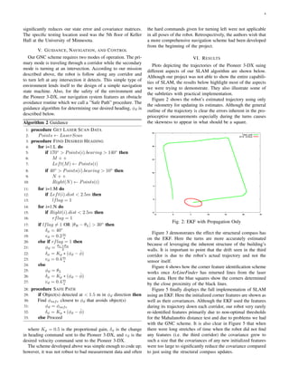
Algorithm 1 Mahalanobis Distance Test
1: procedure FOR EACH MEASUREMENT, zj
2: if mini=1:K Di < γ1 then
3: Associate measurement zj with feature i in EKF Update
4: if γ1 < mini=1:K Di < γ2 then
5: Ignore measurement
6: if mini=1:K Di > γ2 then
7: Initialize new feature
In essence, this test statistically determines if each measure-
ment can be classified as ”close” to, ”far” from an existing
feature i (with the additional classification of ”ambiguous”).
Here by statistical, we mean with regards to the covariance
associated with feature i. This test can also be viewed as an
outlier test for the measurements, assuming each feature is the
true feature.
IV. MISSION
Our project is designed to demonstrate the power of SLAM
in a simple example for a 2D indoor trajectory during
which our Pioneer 3-DX navigates inside a building through
approximately 3 meter wide corridors. By returning to its
original position and successfully re-identifying the features
in that location, we hope to demonstrate an update step that
4. 4
significantly reduces our state error and covariance matrices.
The specific testing location used was the 5th floor of Keller
Hall at the University of Minnesota.
V. GUIDANCE, NAVIGATION, AND CONTROL
Our GNC scheme requires two modes of operation. The pri-
mary mode is traveling through a corridor while the secondary
mode is turning at an intersection. According to our mission
described above, the robot is follow along any corridor and
to turn left at any intersection it detects. This simple type of
environment lends itself to the design of a simple navigation
state machine. Also, for the safety of the environment and
the Pioneer 3-DX, our navigation system features an obstacle
avoidance routine which we call a ”Safe Path” procedure. The
guidance algorithm for determining our desired heading, φd is
described below.
Algorithm 2 Guidance
1: procedure GET LASER SCAN DATA
2: Points ← LaserScan
3: procedure FIND DESIRED HEADING
4: for i=1:L do
5: if 170◦
> Points(i).bearing > 140◦
then
6: M + +
7: Left(M) ← Points(i)
8: if 40◦
> Points(i).bearing > 10◦
then
9: N + +
10: Right(N) ← Points(i)
11: for i=1:M do
12: if Left(i).dist < 2.5m then
13: lflag = 1
14: for i=1:N do
15: if Right(i).dist < 2.5m then
16: rflag = 1
17: if lflag = 1 OR |θR − θL| > 30◦
then
18: δφ = 40◦
19: vd = 0.2m
s
20: else if rflag = 1 then
21: φd = θL+θR
2
22: δφ = Kp ∗ (φd − ˆφ)
23: vd = 0.4m
s
24: else
25: φd = θL
26: δφ = Kp ∗ (φd − ˆφ)
27: vd = 0.4m
s
28: procedure SAFE PATH
29: if Object(s) detected at < 1.5 m in φd direction then
30: Find φsafe closest to φd that avoids object(s)
31: φd = φsafe
32: δφ = Kp ∗ (φd − ˆφ)
33: else Proceed
where Kp = 0.5 is the proportional gain, δφ is the change
in heading command sent to the Pioneer 3-DX, and vd is the
desired velocity command sent to the Pioneer 3-DX.
The scheme developed above was simple enough to code up;
however, it was not robust to bad measurement data and often
the hard commands given for turning left were not applicable
in all poses of the robot. Retrospectively, the authors wish that
a more comprehensive navigation scheme had been developed
from the beginning of the project.
VI. RESULTS
Plots depicting the trajectories of the Pioneer 3-DX suing
different aspects of our SLAM algorithm are shown below.
Although our project was not able to show the entire capabili-
ties of SLAM, the results below highlight most of the aspects
we were trying to demonstrate. They also illustrate some of
the subtleties with practical implementation.
Figure 2 shows the robot’s estimated trajectory using only
the odometry for updating its estimates. Although the general
outline of the trajectory is clear the errors inherent in the pro-
prioceptive measurements especially during the turns causes
the skewness to appear in what should be a square.
Fig. 2: EKF with Propagation Only
Figure 3 demonstrates the effect the structural compass has
on the EKF. Here the turns are more accurately estimated
because of leveraging the inherent structure of the building’s
walls. It is important to point that the drift seen in the third
corridor is due to the robot’s actual trajectory and not the
sensor itself.
Figure 4 shows how the corner feature identification scheme
works once ArLineFinder has returned lines from the laser
scan data. Here the blue squares show the corners determined
by the close proximity of the black lines.
Figure 5 finally displays the full implementation of SLAM
using an EKF. Here the initialized corner features are shown as
well as their covariances. Although the EKF used the features
during its trajectory down each corridor, our robot very rarely
re-identified features primarily due to non-optimal thresholds
for the Mahalanobis distance test and due to problems we had
with the GNC scheme. It is also clear in Figure 5 that when
there were long stretches of time when the robot did not find
any features (i.e. the third corridor) the covariance grew to
such a size that the covariances of any new initialized features
were too large to significantly reduce the covariance compared
to just using the structural compass updates.
5. 5
Fig. 3: EKF with Structural Compass Update
Fig. 4: ArLineFinder Output
VII. CONCLUSIONS
The ability for autonomous robots to concurrently navigate
in an unknown environment while building a map of that
environment is a very powerful tool in robotics, especially
when these robots have no access to GNSS measurements
such as an indoor environment. To illustrate the power of
this algorithm known as SLAM, the authors implemented
SLAM as an EKF on a Pioneer 3-DX robot using odometric
measurements from the Pioneer as well as a mounted 2D
SICK Laser Range Finder. Together, these sensors give enough
information for the successful navigation of the Pioneer robot
inside a general ’Manhattan world’ building.
Our specific implementation of SLAM worked with limited
Fig. 5: EKF with Relative Position Measurements and Struc-
tural Compass
success. Our algorithmic parameters were not optimally tuned
and our navigation filter was not robust to significant errors in
our Laser Range Finder measurements resulting in often er-
roneous navigation trajectories. Although these bugs were not
fixed, our tests did demonstrate the basic principles governing
SLAM estimation.
REFERENCES
[1] A. S. Brown, “Google’s autonomous car applies lessons learned from
driverless races.” Mechanical Engineering, vol. 133, no. 2, p. 31, 2011.
[2] N. Lavars, “Amazon to begin testing new delivery drones in the
US,” Gizmag, April 2015. [Online]. Available: http://www.gizmag.com/
amazon-new-delivery-drones-us-faa-approval/36957/
[3] I. Schworer, “Navigation and control of an autonomous vehicle,” Ph.D.
Thesis, Virginia Polytechnic Institute and State University, April 2005.
[4] SICK LMS200, SICK AG, 2006. [Online]. Available: http://sicktoolbox.
sourceforge.net/docs/sick-lms-technical-description.pdf
[5] Advanced Robot Interface for Applications (ARIA) SDK, MobileRobots
Adept Technology Inc.
[6] “Eigen 3.2.8,” Licensed under MPL2. [Online]. Available: http:
//eigen.tuxfamily.org/index.php?title=Main Page
[7] H. Durrant-Whyte and T. Bailey, “Simultaneous localization and map-
ping: part i,” IEEE Robotics Automation Magazine, vol. 13, no. 2, pp.
99–110, June 2006.
[8] R. Smith, M. Self, and P. Cheeseman, “Estimating uncertain spatial
relationships in robotics,” in Autonomous Robot Vehicles, I. J. Cox and
G. T. Wilfong, Eds. Springer-Verlag New York, Inc., 1990, pp. 167–
193.
[9] H. F. Durrant-Whyte, D. Rye, and E. Nebot, “Localisation of automatic
guided vehicles,” Robotics Research: The 7th International Symposium
(ISRR’95), pp. 613–625, 1996.
[10] M. W. M. G. Dissanayake, P. Newman, S. Clark, H. F. Durrant-
Whyte, and M. Csorba, “A solution to the simultaneous localization
and map building (slam) problem,” IEEE Transactions on Robotics and
Automation, vol. 17, no. 3, pp. 229–241, Jun 2001.
[11] G. P. Huang, A. I. Mourikis, and S. I. Roumeliotis, “Observability-based
rules for designing consistent ekf slam estimators,” The International
Journal of Robotics Research, vol. 29, no. 5, pp. 502–528, 2010.
[12] J. M. Coughlan and A. L. Yuille, “Manhattan world: compass direction
from a single image by bayesian inference,” in Computer Vision, 1999.
The Proceedings of the Seventh IEEE International Conference on,
vol. 2, 1999, pp. 941–947 vol.2.
[13] X. S. Zhou and S. I. Roumeliotis, “Multi-robot slam with unknown
initial correspondence: The robot rendezvous case,” in 2006 IEEE/RSJ
International Conference on Intelligent Robots and Systems, Oct 2006,
pp. 1785–1792.