Download to read offline

![International Research Journal of Engineering and Technology (IRJET) e-ISSN: 2395-0056
Volume: 06 Issue: 04 | Apr 2019 www.irjet.net p-ISSN: 2395-0072
© 2019, IRJET | Impact Factor value: 7.211 | ISO 9001:2008 Certified Journal | Page 645
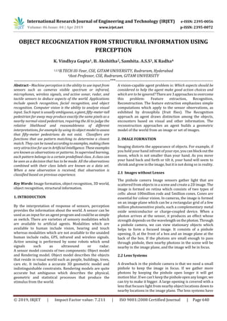
REFERENCES
[1] Artificial intelligence, a modern approach(third edition)
by Stuart J.Russell, Peter Norvig
[2] Wikipedia:https://en.wikipedia.org/wiki/Computer_visi
on
[3] https://en.wikipedia.org/wiki/Speech_recognition](https://image.slidesharecdn.com/irjet-v6i4145-190620063529/85/IRJET-Object-Recognization-from-Structural-Information-using-Perception-6-320.jpg)

This document summarizes research on object recognition from images using machine perception techniques. It discusses how machine perception works by using sensor input like cameras to deduce aspects of the world. It then describes various methods researchers are using for object recognition, including extracting features from images, training classifiers to recognize objects, and reconstructing 3D models of objects and scenes from 2D images. Key techniques discussed include using histograms of oriented gradients to recognize pedestrians, exploiting motion parallax and binocular stereopsis to derive depth from multiple images, and analyzing texture, shading and other visual cues to help reconstruct 3D worlds from 2D inputs.