Download as PDF, PPTX
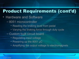
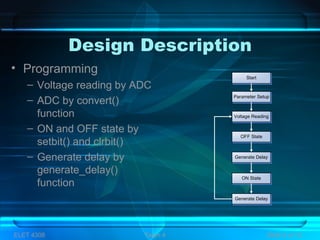
![Design Specifications (cont’d)
• General view
– Pedal
– 8015 Microcontroller
– Circuit board
– Electromagnets
– DC power supply
Pedal
8051 µC
EM
DC
power
supply
Circuit
board
5 [V]
output
Input
Square
Wave
12 [V]
power
42 [V]
power
Amplified
output
ELET 4308 Team 4 Slide 7 of 13](https://image.slidesharecdn.com/electromagneticbrakingsystem-151220144403/85/Electromagnetic-braking-system-8-320.jpg)


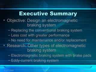
The document describes the design of an electromagnetic braking system as an alternative to conventional braking systems. Key points: - The objective is to design an electromagnetic braking system that is less costly and higher performing than traditional braking, and requires no maintenance. - The design will use an 8051 microcontroller to control three electromagnets based on input from a brake pedal. This will generate braking force electronically rather than through brake pads. - Alternatives considered were permanent magnets or metallic material around the wheel, but these had issues with cleaning, arrangement, or not providing enough braking force. - The final design specifications include an 8051 microcontroller, Toyota hub/sp


