Download to read offline
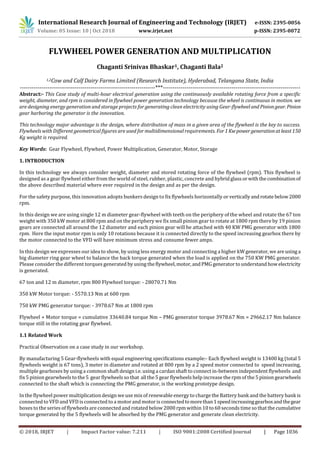

![International Research Journal of Engineering and Technology (IRJET) e-ISSN: 2395-0056
Volume: 05 Issue: 10 | Oct 2018 www.irjet.net p-ISSN: 2395-0072
© 2018, IRJET | Impact Factor value: 7.211 | ISO 9001:2008 Certified Journal | Page 1045
ACKNOWLEDGEMENT
[1] IEEE Submission
1570315771: Still Water Electrical Generation
[2] Climate samurai renewable energy Magazine publication:
https://view.publitas.com/climatesamurai-com/climate-samurai-january-2018-issue/page/16-17
REFERENCES
[1] https://www.furukawa.co.jp/en/release/2015/kenkai_150415.html
[2] https://en.wikipedia.org/wiki/Joint_European_Torus](https://image.slidesharecdn.com/irjet-v5i10194-181102112713/85/IRJET-Flywheel-Power-Generation-and-Multiplication-10-320.jpg)


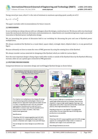
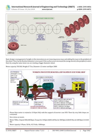
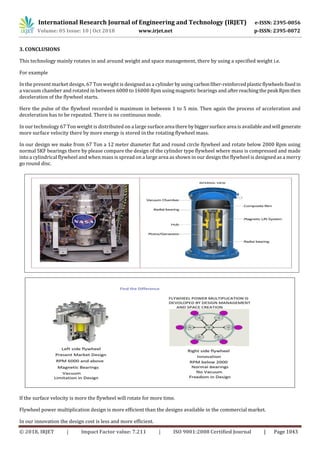
This document describes a flywheel power generation technology that uses a large gear-flywheel to store rotational energy and multiply power output. A 67-ton, 12-meter diameter flywheel is rotated at 800 rpm by a 350 kW motor. Pinion gears attached around the flywheel's perimeter increase its rpm to 1800, which rotates a 750 kW permanent magnet generator to produce electricity. The flywheel stores energy based on its mass distribution and large diameter, allowing continuous power generation without stopping as the stored rotational energy is transferred to the generator. Experiments showed that an 11-ton, 2-meter flywheel could rotate a generator for over 30 minutes after the motor was disconnected, demonstrating the technology's ability to provide sustained power generation.