Download to read offline
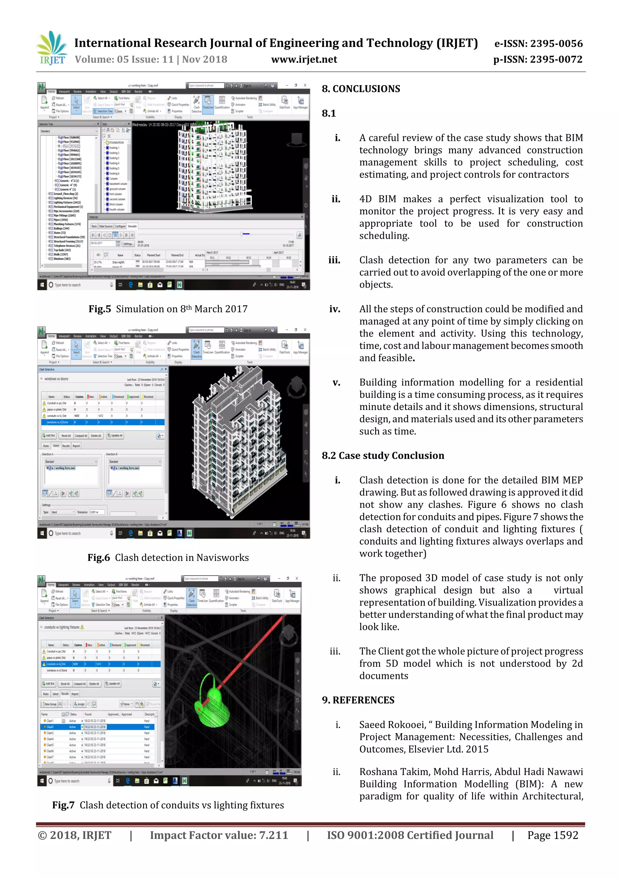
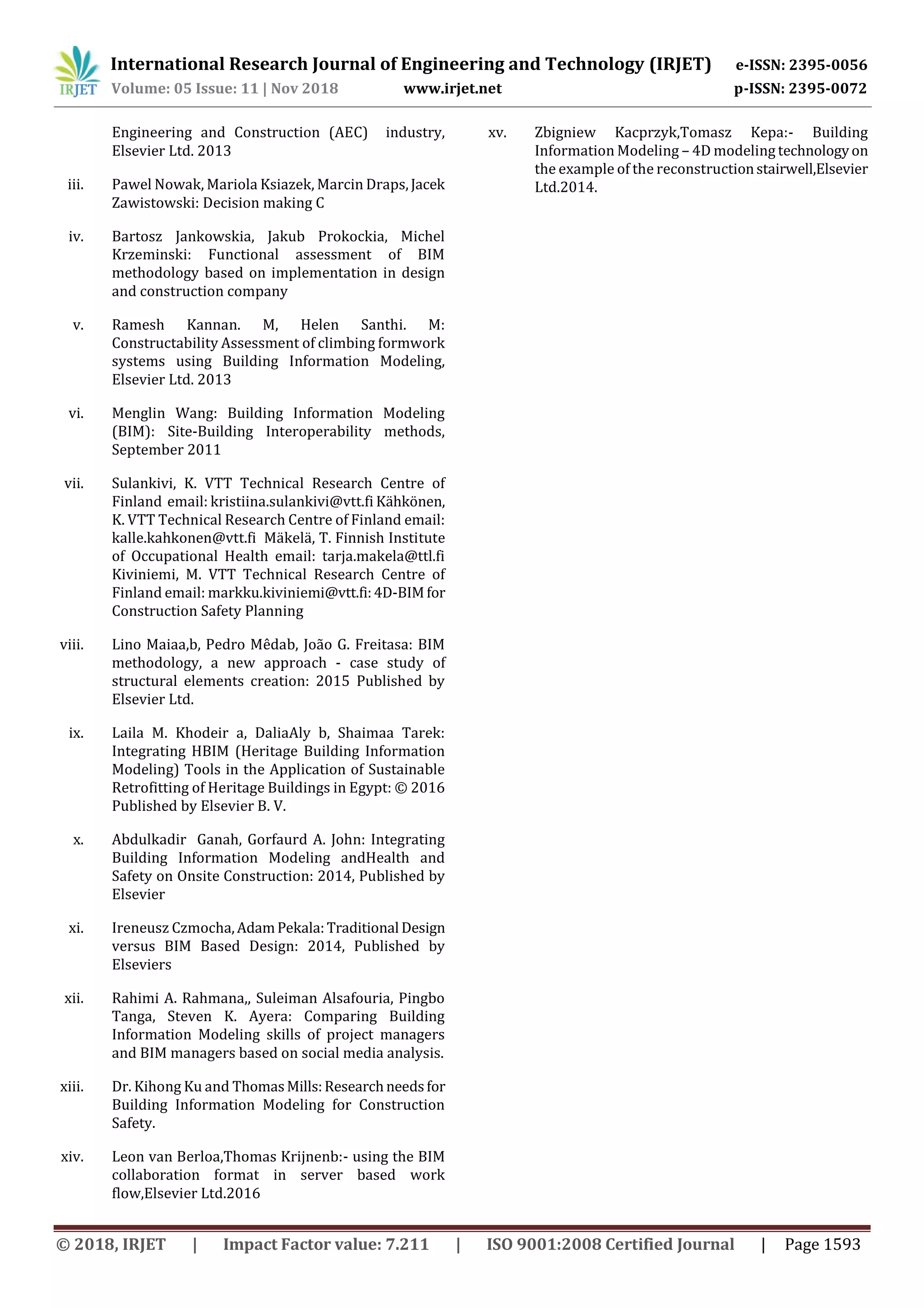

This document discusses 4D simulation of mechanical, electrical, and plumbing (MEP) systems using building information modeling (BIM) for a residential building project. It begins with an introduction to BIM and its benefits for project planning, design, and construction. Software used includes Autodesk Revit for the 3D building model, Autodesk Revit MEP for MEP modeling, and Autodesk Navisworks for 4D simulation and clash detection. A sample residential building project is modeled in these programs to demonstrate linking the 3D model to a schedule in Navisworks for 4D visualization and analysis of the construction process. The conclusions state that 4D BIM is an effective tool for construction scheduling,


