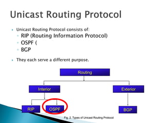
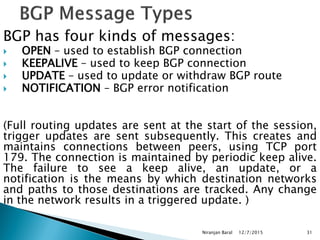
Routing protocols exchange information to determine the best paths between sources and destinations in a network. The document discusses several routing protocols:
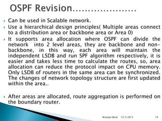
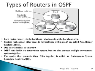
Distance vector protocols like RIP propagate routing tables between routers periodically. They are simple to configure but slow to converge. Link state protocols like OSPF use link state advertisements to build a map of the network and calculate the lowest cost paths more quickly. OSPF divides large networks into areas to reduce routing table sizes and convergence times. It elects routers on area borders to aggregate routing information between areas.
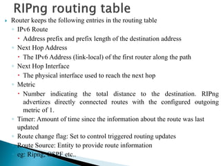
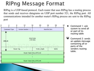
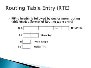
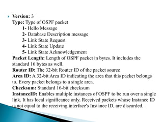
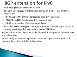
![ IPv6 Prefix: 128 bits address of the network whose information is being carried.
Route Tag
It may be used to carry additional information about a route learned from another
routing protocol eg: BGP
◦ Prefix Length: The no of bits of the adress that represents the network portion.
The number of RTEs within single updates depends on the MTU of the medium
between two neighboring routers
No of RTEs=[INT(MTU-IPv6 Hdr len-UDP Hdr len -RIPng Hdr len) / RTE-Size]
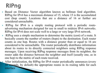
Timers
◦ RIPng uses different timers to control updates of the routing information
◦ Update timer
By default, every 30 seconds, RIPng process wakesup on each interface to
send an unsolicited routing response to the neighboring routers](https://image.slidesharecdn.com/ipv6routing-220324041515/85/IPv6-Routing-pdf-11-320.jpg)
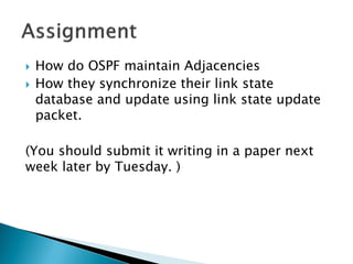
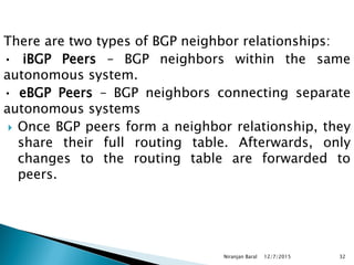
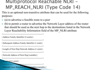
![Using the LSDB as the input, each router runs the same algorithm to
build a tree of least-cost paths (shortest-path-first tree [SPF tree]) to each
route. The LSDB is like having a map of the network used to plot the
shortest paths to each destination. The cost is described by a single
dimensionless metric, which is configurable on each interface of the
router.
The metric assigned to the interface is usually inversely proportional to
its line speed, i.e., higher bandwidth means lower cost. A common
formula was to divide 10^8 by the line speed in bits per second. This
formula is outdated as interface speed today is in the range of 10^9 (e.g.,
Gigabit Ethernet) or even 10^10. Most vendors today apply a nonlinear
formula. You can always choose and implement your own cost metrics
according to corporate standards. OSPF can put multiple equal-cost paths
to the same route into the routing table. The algorithm for distributing
traffic among these paths is at the discretion of the routing process itself,
normally based on the source and destination IPv6 addresses.](https://image.slidesharecdn.com/ipv6routing-220324041515/85/IPv6-Routing-pdf-14-320.jpg)
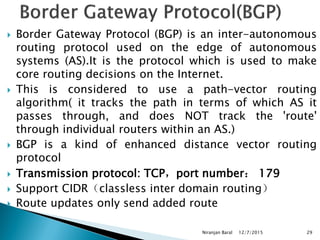
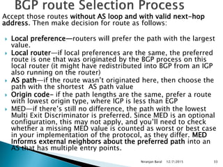
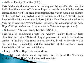
![ Protocol Processing Per-Link, Not Per-Subnet
Multiple IPv6 subnets can be assigned to a single link, and two nodes can talk directly over a single
link, even if they do not share a common IPv6 subnet (IPv6 prefix). For this reason, OSPF for IPv6
runs per-link instead of the IPv4 behavior of per-IP-subnet. The terms "network" and "subnet" used in
the IPv4 OSPF specification ([OSPFV2]) should generally be replaced by link.
Removal of addressing semantics
IPv6 addresses are no longer present in OSPF packet headers. They are only allowed as payload
information
Addition of Flooding Scope
Flooding scope for LSAs has been generalized and is now explicitly coded in the
LSA’s LS type field. There are now three separate flooding scopes for LSAs:
o Link-local scope. LSA is only flooded on the local link and no further. Used for the
new link-LSA.
o Area scope. LSA is only flooded throughout a single OSPF area. Used for router-
LSAs, network-LSAs, inter-area-prefix-LSAs, interarea-router-LSAs, and intra-area-
prefix-LSAs.
o AS scope. LSA is flooded throughout the routing domain. Used for AS-external-
LSAs. A router that originates AS scoped LSAs is considered an AS Boundary Router
(ASBR) and will set its E-bit in router-LSAs for regular areas.](https://image.slidesharecdn.com/ipv6routing-220324041515/85/IPv6-Routing-pdf-21-320.jpg)
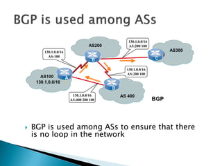
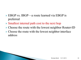
![ Explicit Support for Multiple Instances per Link
Ability to run multiple OSPF protocol instances on a single link. Support for multiple
protocol instances on a link is accomplished via an "Instance ID" contained in the
OSPF packet header and OSPF interface data structures.
Use of Link-Local Addresses
IPv6 link-local addresses are for use on a single link, for purposes of neighbor
discovery, auto-configuration, etc. IPv6 routers do not forward IPv6 datagrams having
link-local source addresses [IP6ADDR]. Link-local unicast addresses are assigned
from the IPv6 address range FE80/10
Authentication Changes
In OSPF for IPv6, authentication has been removed from the OSPF protocol. The
"AuType" and "Authentication" fields have been removed from the OSPF packet
header, and all authentication-related fields have been removed from the OSPF area
and interface data structures. When running over IPv6, OSPF relies on the IP
Authentication Header (see [IPAUTH]) and the IP Encapsulating Security Payload (see
[IPESP]) as described in [OSPFV3-AUTH] to ensure integrity and
authentication/confidentiality of routing exchanges.](https://image.slidesharecdn.com/ipv6routing-220324041515/85/IPv6-Routing-pdf-22-320.jpg)

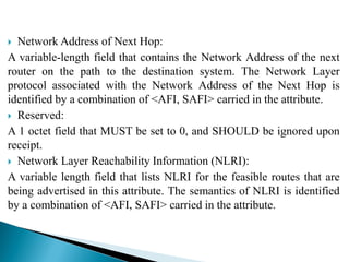
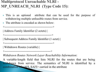
![ Error Handling
If a BGP speaker receives from a neighbor an UPDATE message that contains
the MP_REACH_NLRI or MP_UNREACH_NLRI attribute, and if the
speaker determines that the attribute is incorrect, the speaker MUST delete all
the BGP routes received from that neighbor whose AFI/SAFI is the same as
the one carried in the incorrect MP_REACH_NLRI or MP_UNREACH_NLRI
attribute. For the duration of the BGP session over which the UPDATE
message was received, the speaker then SHOULD ignore all the subsequent
routes with that AFI/SAFI received over that session.
Use of BGP Capability Advertisement
A BGP speaker that uses Multiprotocol Extensions should use the Capability
Advertisement procedures [BGP-CAP] to determine whether the speaker
could use Multiprotocol Extensions with a particular peer. The Capability
Code field is set to 1 (which indicates Multiprotocol Extensions
capabilities). The Capability Length field is set to 4. The Capability Value
field is defined as:
0 7 15 23 31
+-------+-------+-------+-------+
| AFI | Res. | SAFI |
+-------+-------+-------+-------+](https://image.slidesharecdn.com/ipv6routing-220324041515/85/IPv6-Routing-pdf-41-320.jpg)
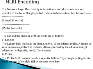
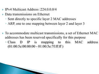
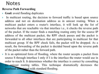
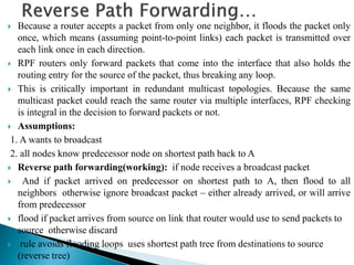
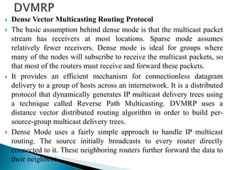
![ Multicast Routing are used to distribute data to multiple recipients. Using
multicast, a source can send a single copy of data to a single multicast
address, which is then distributed to an entire group of recipients. In
multicasting, the router may forward the received packets through several
of its interface. In this case, router may copy the data when it is necessary,
and forward it to the receivers.
[A multicast is similar to a broadcast in the sense that its target is a number
of machines on a network, but not all. Where a broadcast is directed to all
hosts on the network, a multicast is directed to a group of hosts. The hosts
can choose whether they wish to participate in the multicast group (often
done with the Internet Group Management Protocol), whereas in a
broadcast, all hosts are part of the broadcast group whether they like it or
not!]
A multicast group identifies a set of recipients that are interested in a
particular data stream, and is represented by an IP address from a well-
defined range. Data sent to this IP address is forwarded to all members of
the multicast group.](https://image.slidesharecdn.com/ipv6routing-220324041515/85/IPv6-Routing-pdf-43-320.jpg)
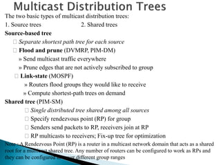
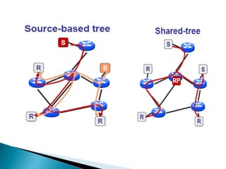
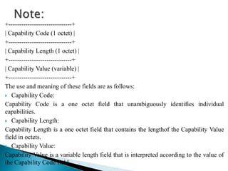
![ Protocol Independent Multicasting- Sparse Mode
PIM-SM is called "protocol independent" because it can use the route
information that any routing protocol enters into the multicast Routing
Information Base (RIB).
Examples of these routing protocols include unicast protocols such as the
Routing Information Protocol (RIP) and Open Shortest Path First (OSPF),
but multicast protocols that populate the routing tables—such as the
Distance Vector Multicast Routing Protocol (DVMRP)—can also be used.
Sparse mode means that the protocol is designed for situations where
multicast groups are thinly populated across a large region. Sparse-mode
protocols can operate in LAN environments, but they are most efficient over
WANs. A sparse group can be defined as "one in which
a) the number of networks or domains with group members present is
significantly smaller than the number of networks/domains in the Internet,
b) group members span an area that is too large/wide to rely on a hop-count
limit or some other form of limiting the scope of multicast packet
propagation, and c) the internetwork is not sufficiently resource rich to
ignore the overhead of current [dense mode] schemes.](https://image.slidesharecdn.com/ipv6routing-220324041515/85/IPv6-Routing-pdf-56-320.jpg)