Downloaded 130 times
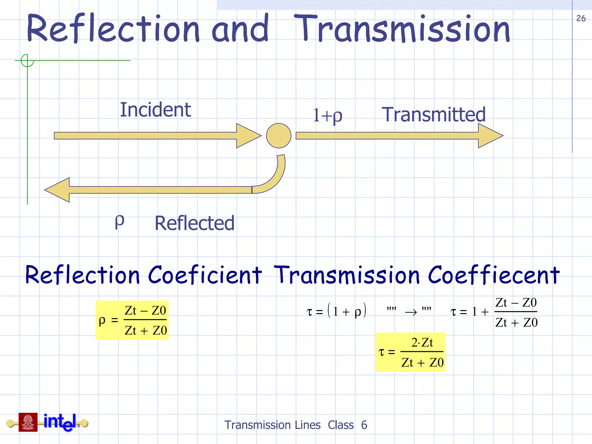
![General Characteristics of Transmission Line Propagation delay per unit length ( T 0 ) { time/distance} [ps/in] Or Velocity ( v 0 ) {distance/ time} [in/ps] Characteristic Impedance ( Z 0 ) Per-unit-length Capacitance ( C 0 ) [pf/in] Per-unit-length Inductance ( L 0 ) [nf/in] Per-unit-length (Series) Resistance ( R 0 ) [ /in] Per-unit-length (Parallel) Conductance ( G 0 ) [S/in] T-Line Equivalent Circuit Transmission Lines Class 6 lL 0 lR 0 lC 0 lG 0](https://image.slidesharecdn.com/class06transmissionlinebasics-110928092121-phpapp01/75/Class06-transmission-line_basics-13-2048.jpg)
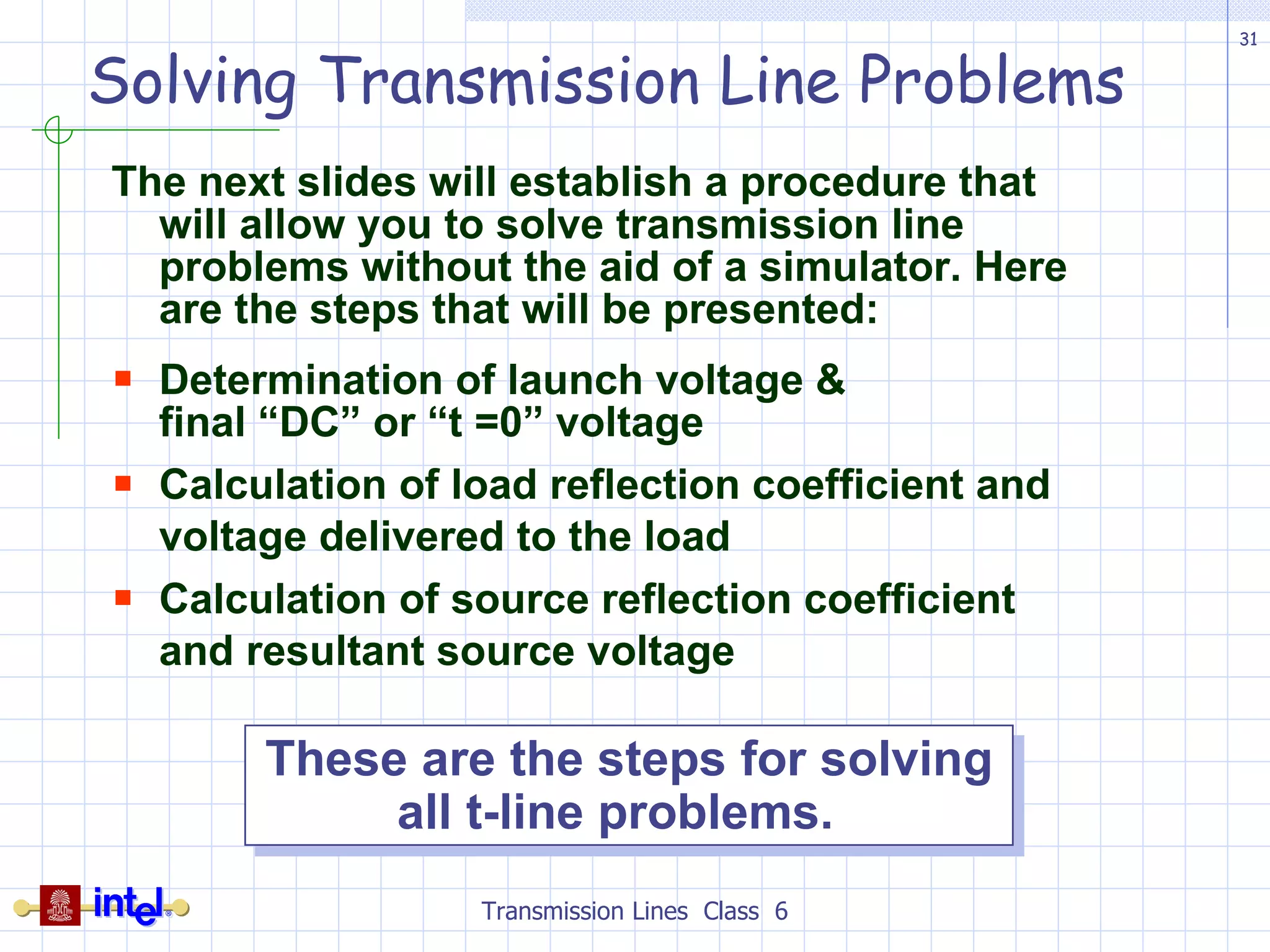
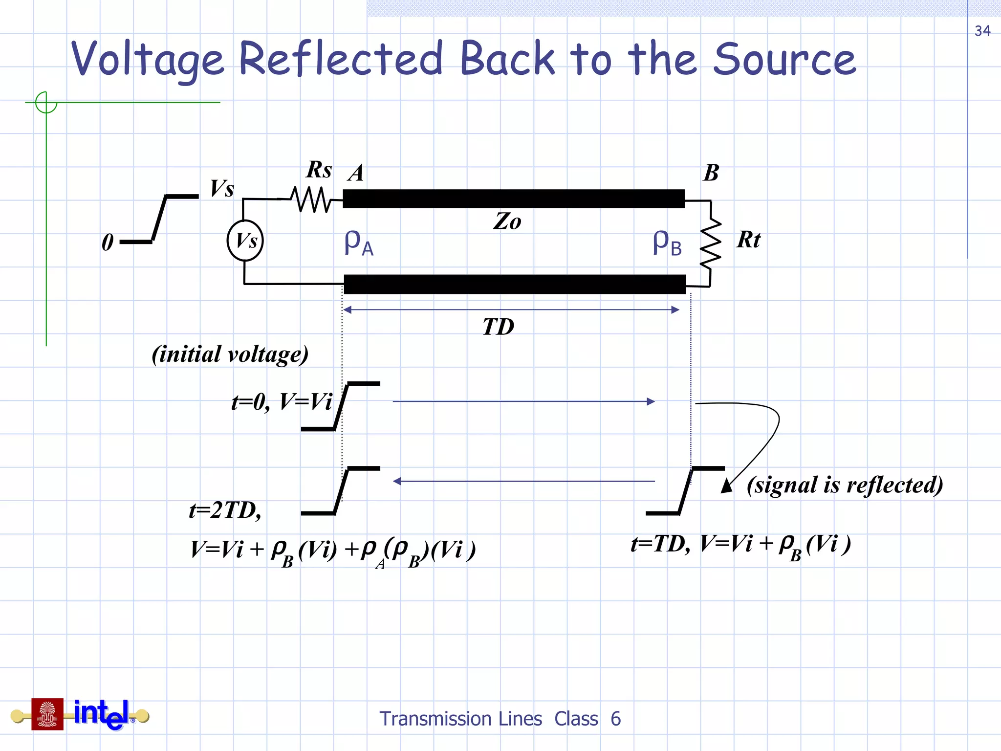
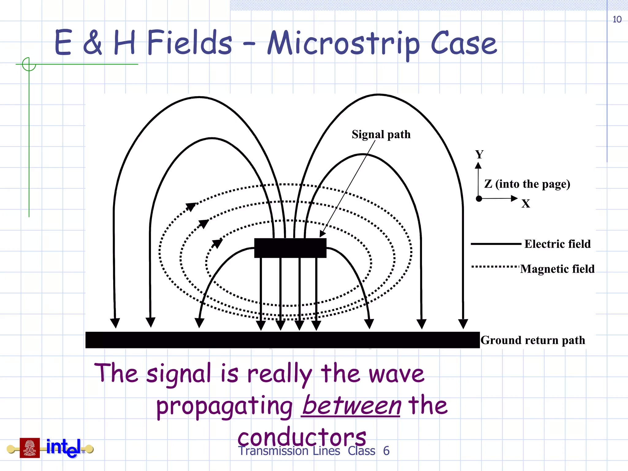
![Voltage Reflected Back to the Source Transmission Lines Class 6 Step 3: Determine V A in the circuit at time t = 2TD The transient behavior of transmission line delays the arrival of voltage reflected from the load until time t = 2TD. V A at time 0 < t < 2TD is at launch voltage Voltage wavefront will be reflected at the source V A = V launch + V incident + V reflected at time t = 2TD In the steady state, the solution converges to V B = V S [R t / (R t + R s )] Zo Rs Zo Rs V reflected = (V incident ) V A = V launch + V incident + V reflected](https://image.slidesharecdn.com/class06transmissionlinebasics-110928092121-phpapp01/75/Class06-transmission-line_basics-35-2048.jpg)

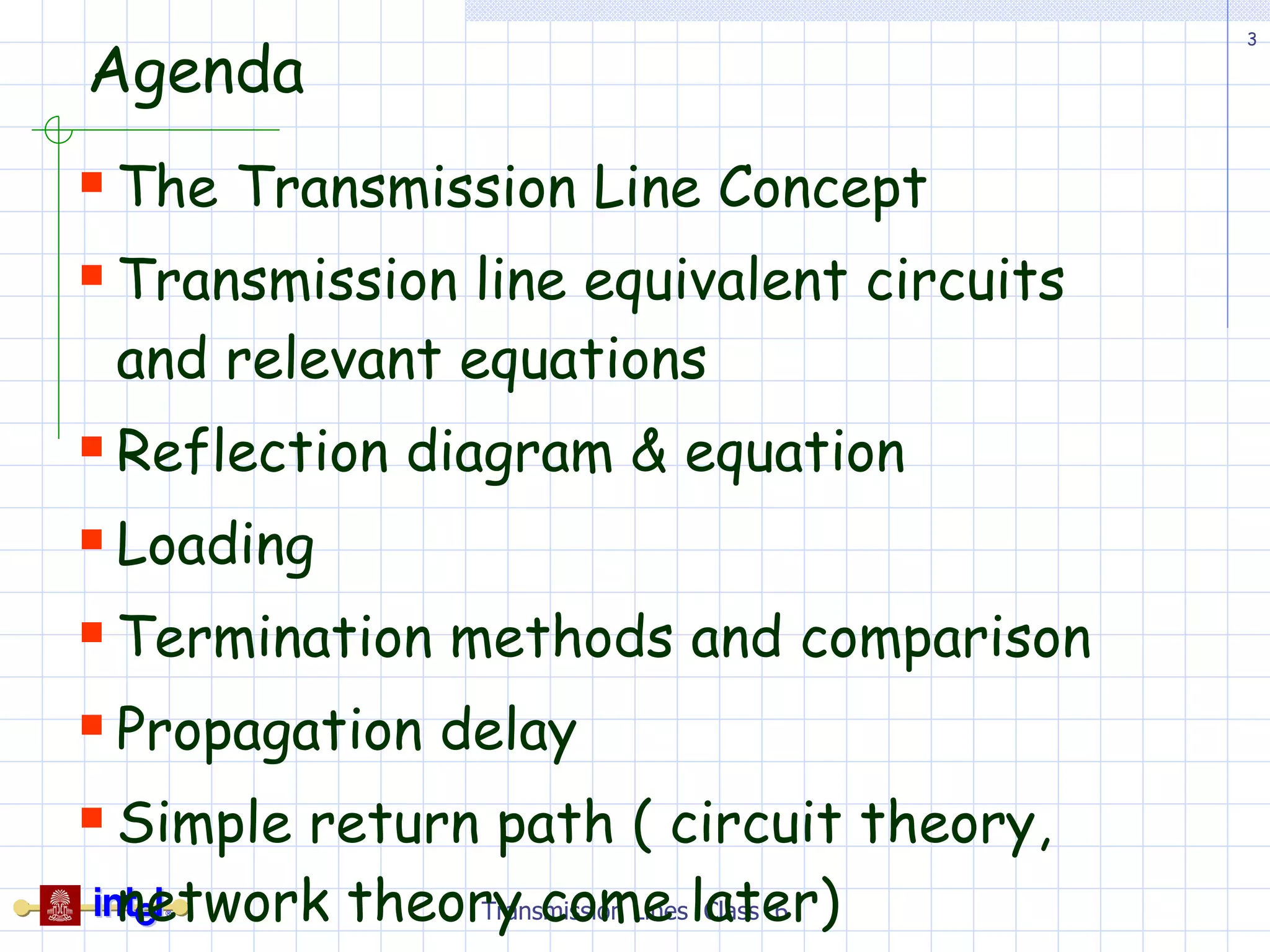
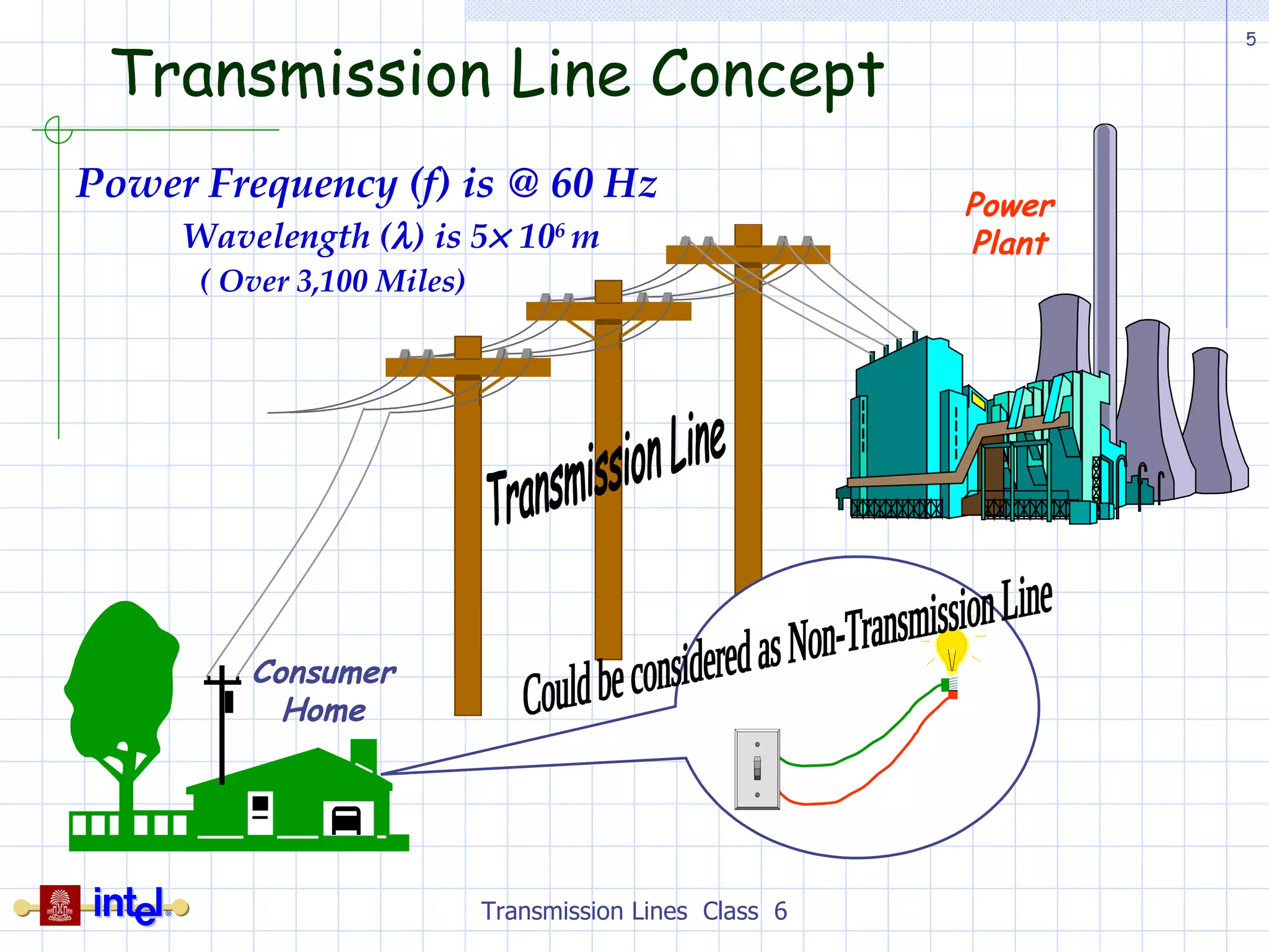
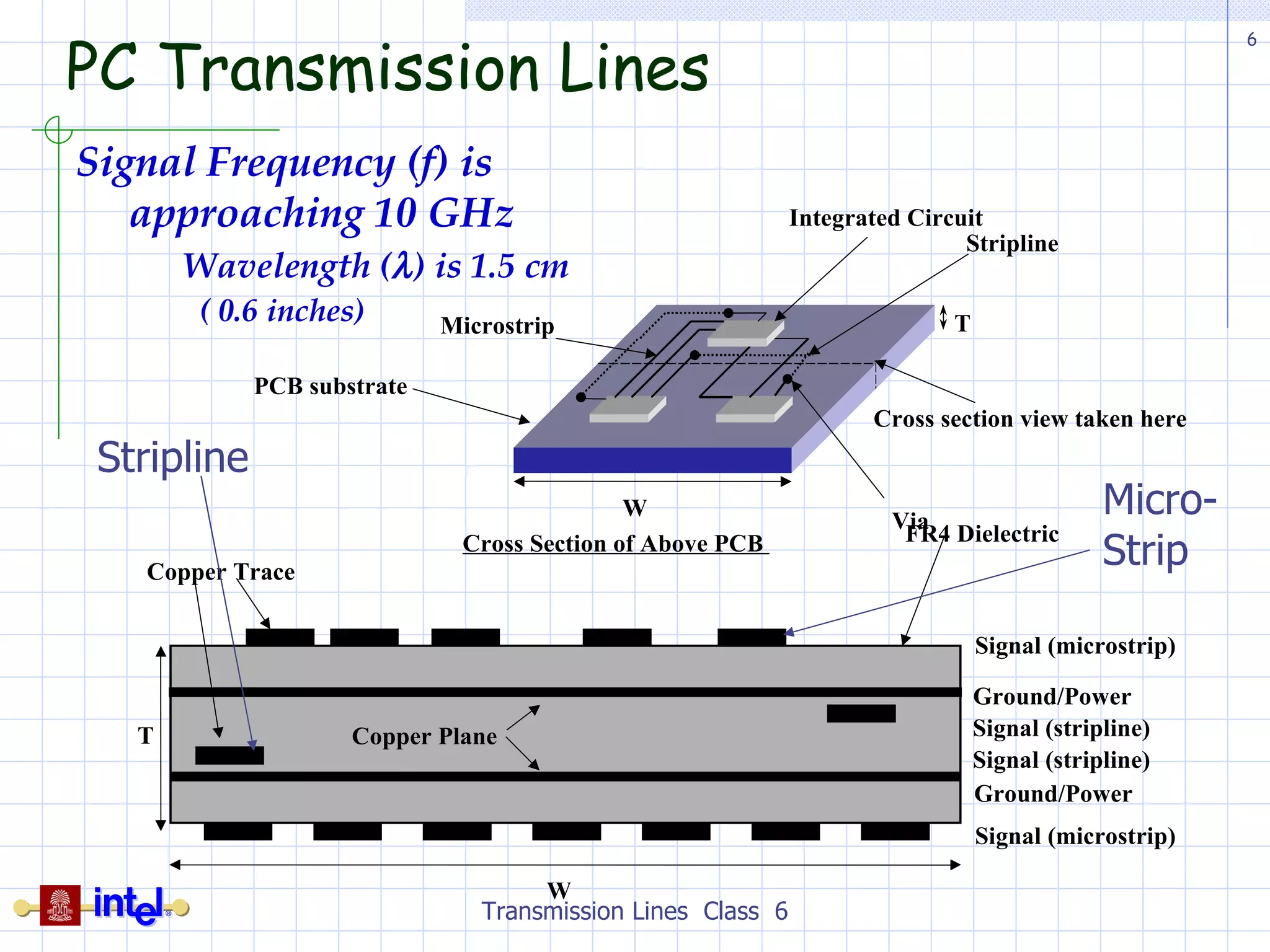
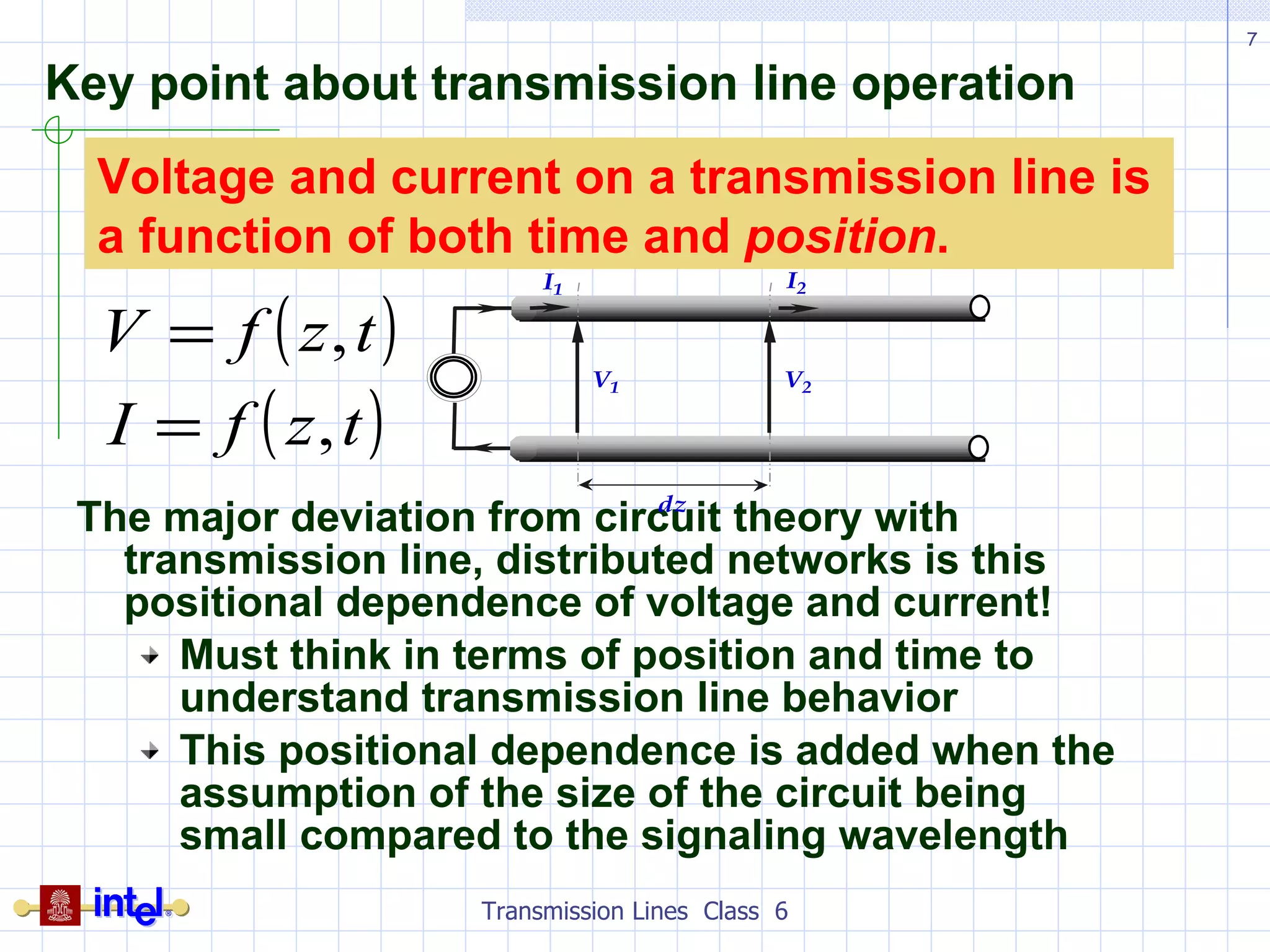
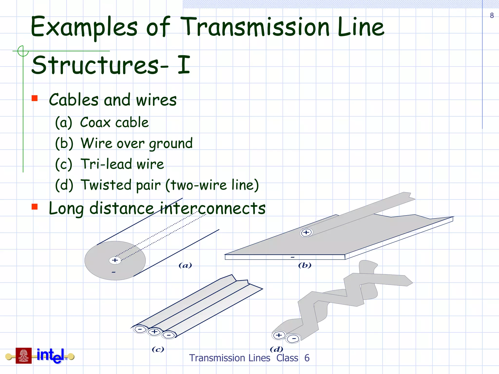
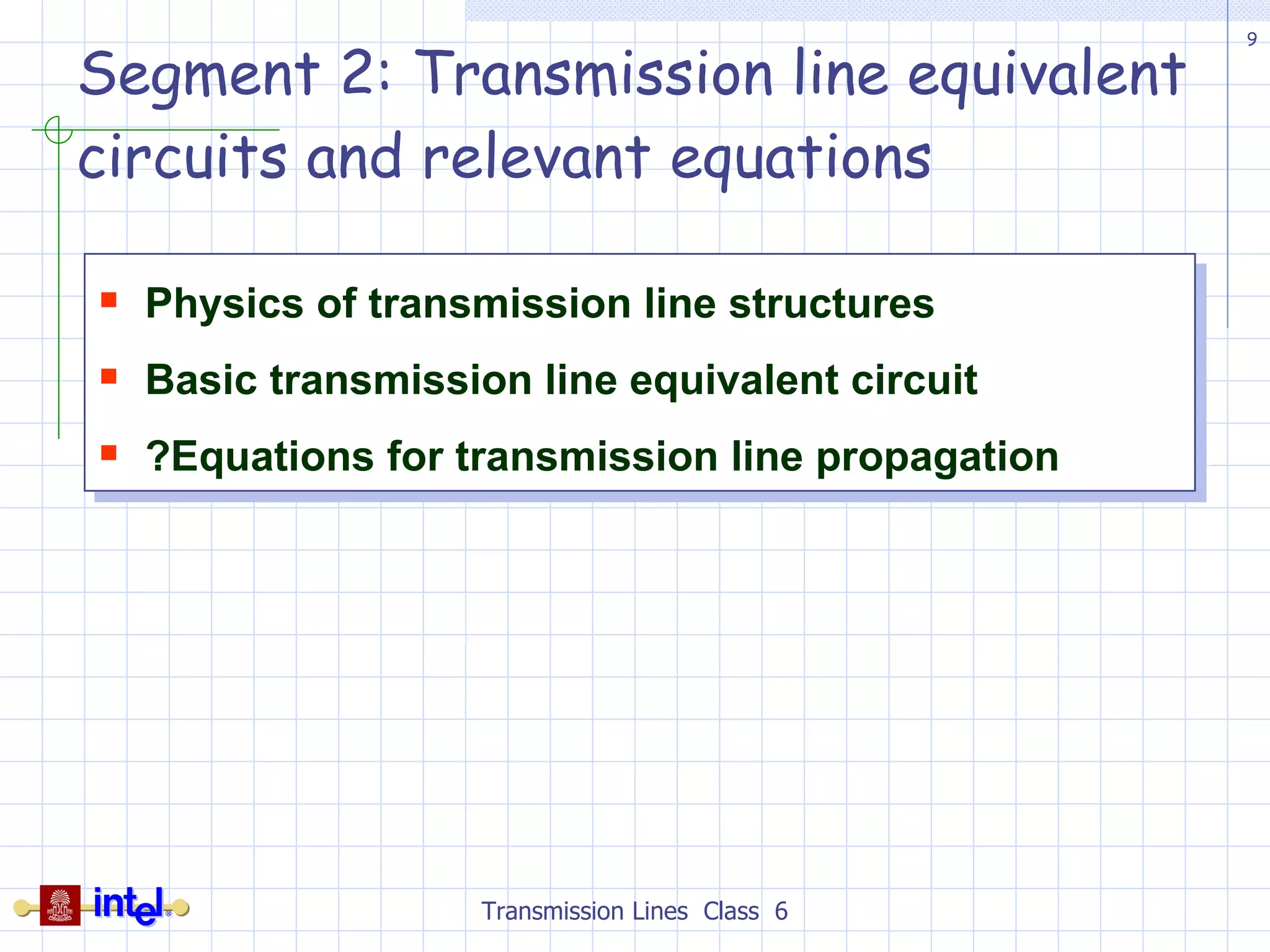
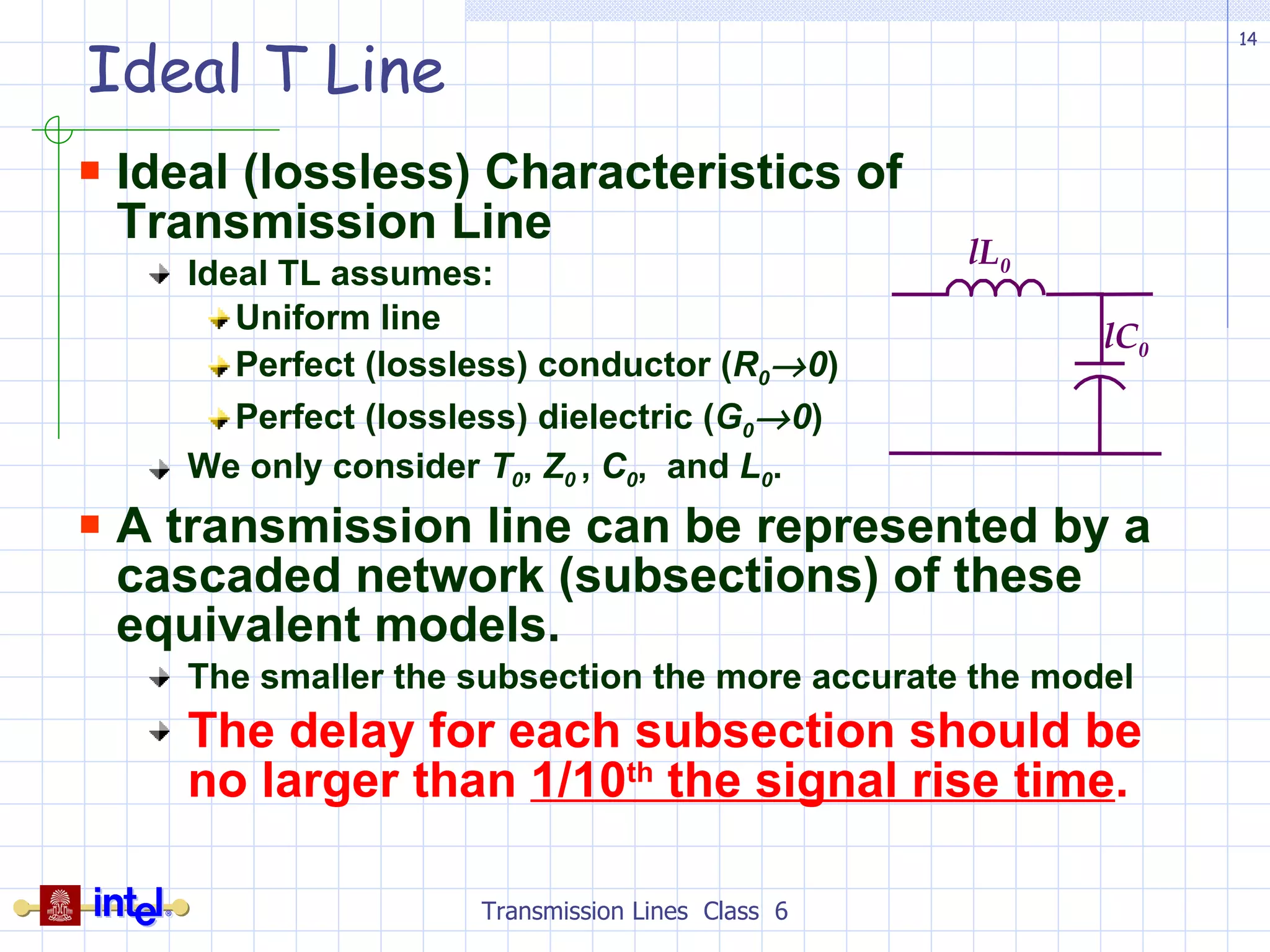
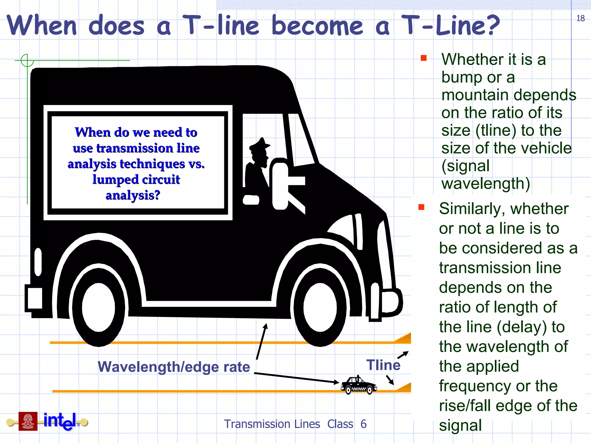
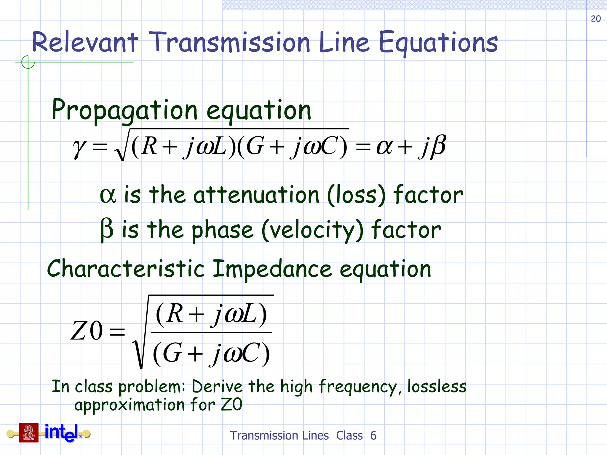
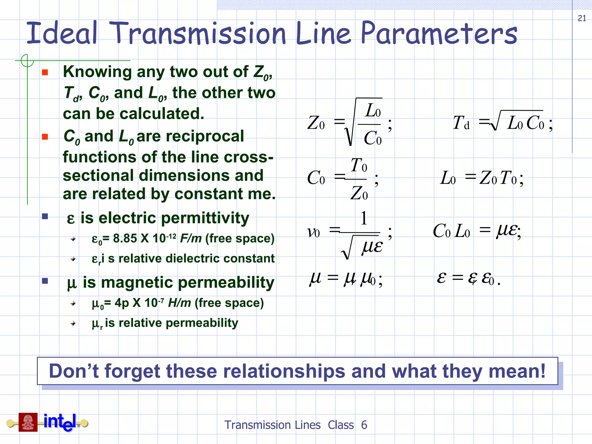
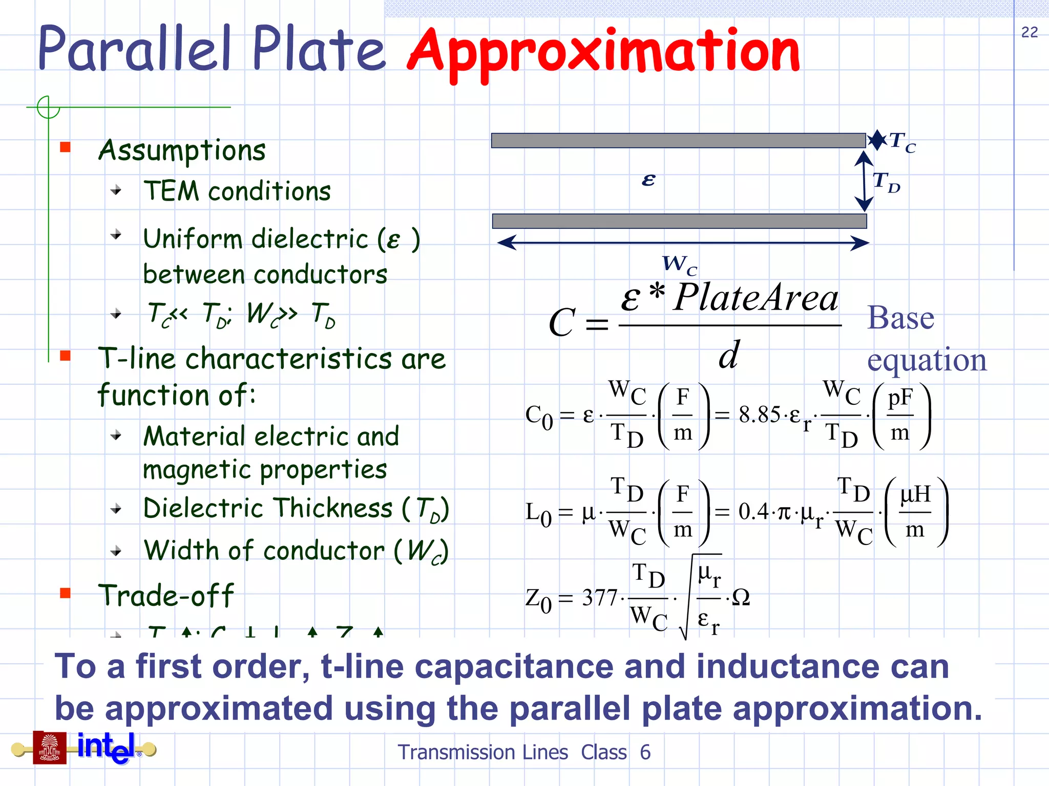
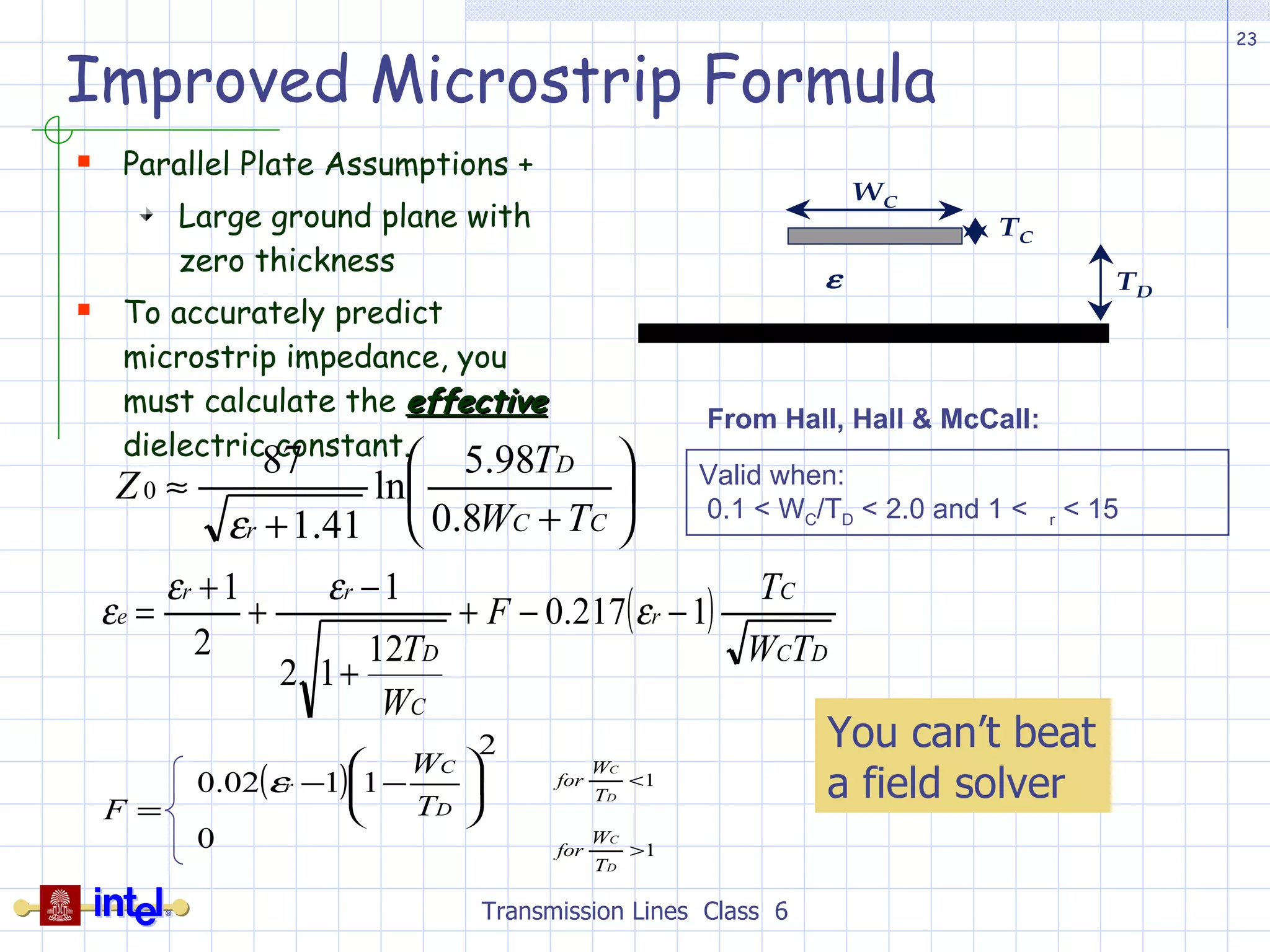
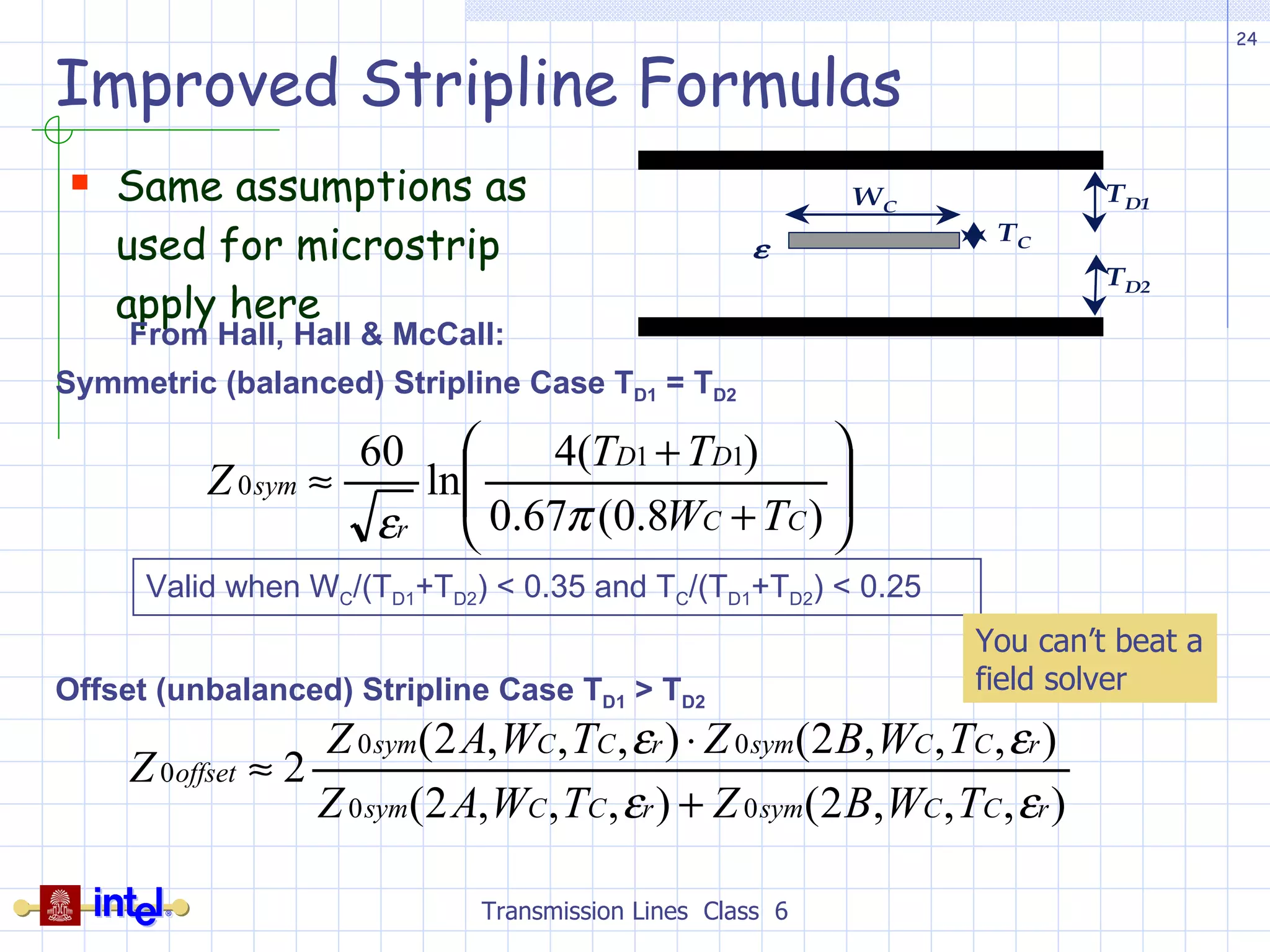
This document provides an overview of transmission line basics and concepts. It discusses key transmission line parameters like characteristic impedance, propagation delay, per-unit-length capacitance and inductance. It covers transmission line equivalent circuit models and relevant equations. It also discusses transmission line structures, parallel plate approximations, reflection coefficients, and discontinuities. The goal is to understand transmission line behavior and analysis techniques.


![RF Module Design - [Chapter 6] Power Amplifier](https://cdn.slidesharecdn.com/ss_thumbnails/rfch6-150613070347-lva1-app6891-thumbnail.jpg?width=640&height=640&fit=bounds)


