Downloaded 374 times
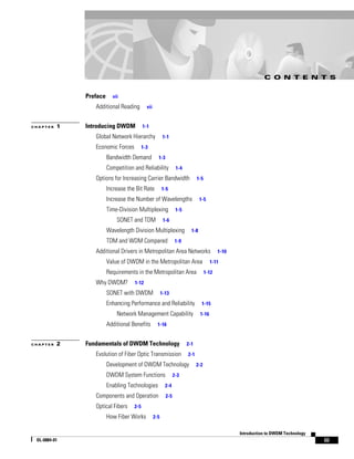


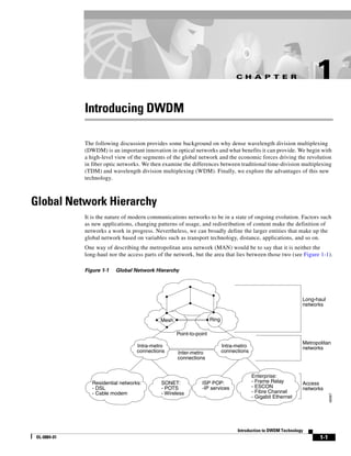


This document provides an introduction to Dense Wavelength Division Multiplexing (DWDM) technology. It discusses the economic drivers pushing for increased bandwidth in networks, and describes DWDM as an option for increasing carrier bandwidth by allowing multiple wavelengths of light to be transmitted simultaneously along the same fiber. The document outlines some key components of DWDM systems, such as optical fibers, light sources and detectors, optical amplifiers, and multiplexers/demultiplexers. It also notes some benefits of using DWDM with SONET, such as enhanced performance, reliability, and network management capabilities.
![DWDM & Packet Optical Fundamentals by Dion Leung [APRICOT 2015]](https://cdn.slidesharecdn.com/ss_thumbnails/dwdmpackettutorialapricot20151425453497-150304173624-conversion-gate01-thumbnail.jpg?width=640&height=640&fit=bounds)


