Download to read offline
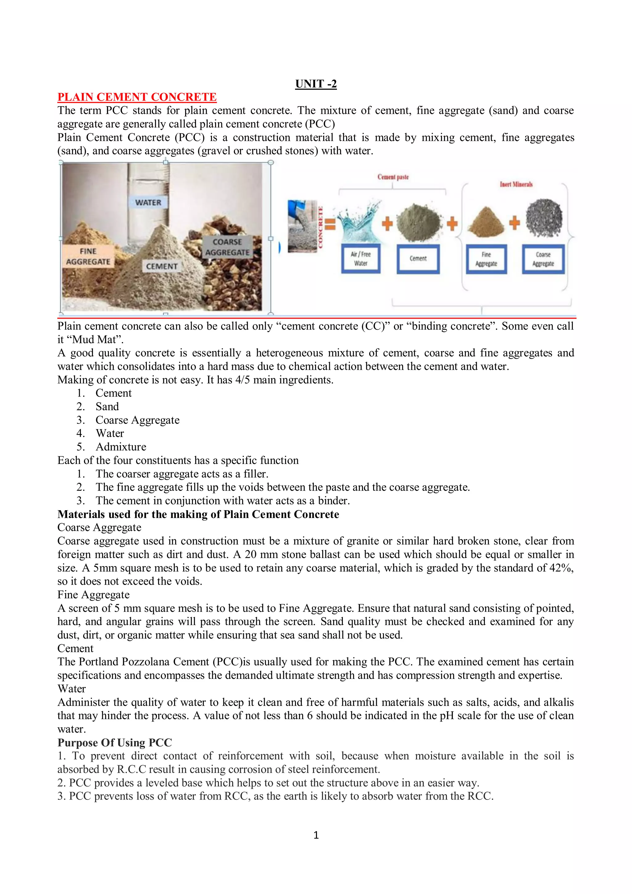


Plain cement concrete (PCC) is a construction material made by mixing cement, fine aggregates like sand, and coarse aggregates like gravel or crushed stone with water. It is used in foundations, pavements, retaining walls, floor slabs, and other applications due to its compressive strength and ability to withstand loads. PCC consists mainly of cement, sand, coarse aggregate, and water. It is laid in layers not more than 150mm thick and cured for at least 14 days to gain strength and hardness. Common uses of PCC include as a base for building foundations, in pavements, retaining walls, floor slabs, bridges, driveways, and for precast concrete elements.