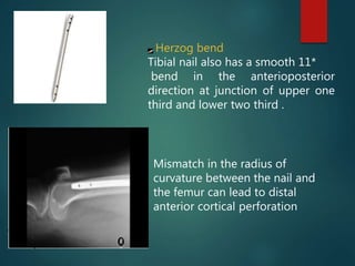
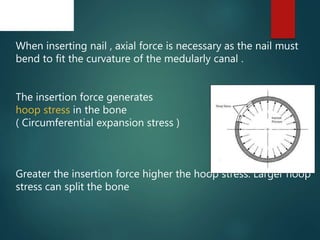
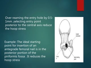
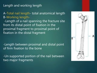
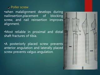
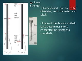
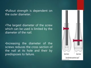
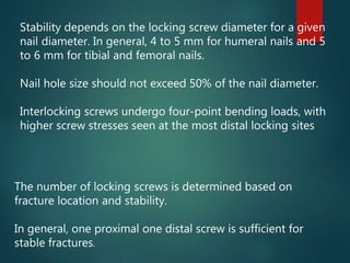
PRINCIPLES OF
INTRAMEDULLARY
NAILING
PRESENTED BY : DR. ANAND MISHRA
PG ,ORTHOPAEDICS
INTRAMEDULLARY NAILING
The intramedullary nail is commonly used for long-bone
fracture fixation and has become the standard treatment
of most long-bone diaphyseal and selected metaphyseal
fractures
To understand the intramedullary nail, knowledge of
evolution and biomechanics are helpful
HISTORY
In 16 th Century In Mexico Aztec physicians have placed
wooden sticks into the medullary canals of patients with long
bone non-union.
In Mid 1800’s Ivory pegs were inserted into the medullary
canal for non-union. In1917 ‘s Hoglund of United States
reported the use of autogenous bone as a intramedulary
implant.
1930’s In the United States, Rush and Rush described the
use of Steinman pins placed in the medullary canal to treat
fractures of the proximal ulna and proximal femur.
1940 ‘s : The Evolution of Kűntscher Nailing
Gerhard Kűntscher was born in Germany in 1900
1931 : Smith-Petersen reported the success of stainless
steel nails for the treatment of NOF #s
1940’s:
Gerard
Küntscher developed ‘V’
nail, Cloverleaf shaped and
the ‘Y’ nail.
His methods were based on
two principles: stable fixation
and closed nailing. .
.
Harvey C. Hansen and Dana
M. Street developed a diamond
shaped nail which is relied on
the holding power of cancellous
bone at both ends. He termed
the word ‘Bolt
Lottes designed three flanged
femur and tibial nails. Both nails
employed a screw-on driver-
extractor
1950’s:
Stryker designed a broach in
a cloverleaf and diamond
shaped pattern. It provided
maximum holding power to
resist torque and avoided
reaming the entire canal
circumference.
.
.
Schneider designed his nail
which incorporated a double-
ended stud, self broaching and
fluted with a square cross
section
1950’s Interlocking Screws :
Modny and Bambara introduced
the transfixion intramedullary
nail in 1953
Nailing of tibia is introduced by
herzog in 1950.
Livingston bar,introduced a
short I-beam pattern pointed
nail at both ends,which had
short slots for cross-pinning with
screws
INTRODUCTION
 Today any fracture is stabilized by one of the two
systems of fracture fixation .
1. compression system
2. splinting system
Intramedullary fixation belongs to internal splinting
system.
Splintage may be defined as a construct in which
micromotion can occur between bone & implant,
providing only relative stability without interfragmentary
compression.
 Depending on the anatomy the insertion can be ante
grade and retrograde.
 The entry point depends on the anatomy of the bone
but is distant from the fracture site.
 Intramedullary fixation techniques offer the advantages
of closed reduction and closed fixation.
INTRAMEDULLARY DEVICES ARE
BROADLY CLASSIFIED INTO:
 A.) CENTROMEDULLARY- K NAIL,FIRST
GENERATION IM NAIL
 B.) CEPHALOMEDULLARY- GAMMA NAIL,
RUSSELL TAYLOR NAIL,UNIFLEX, PFN
 C.) CONDYLOCEPHALIC NAIL- ENDER
NAIL,LOTTES ETC
c o n d y l o c e p h a l i c f i x a t i o n
•Also known as elastic stable intramedullary nailing
(ESIN), is a primary definitvie fracture care (PDFC) in
paediatric orthopaedic practice.
•This method works by 3 – point fixation or bundle
nailing.
•The elasticity of the construct allows for ideal
cirumstances of micro-motion for rapid fracture healing.
 Nonreamed nails are actually not nails but pins.
Their mechanical characteristics and use are
different from IM nails. They are of smaller
diameter and are more elastic.
 Their flexibility allows insertion through a cortical
window. There are many different types of
flexible nails, the best known are:-
 Lottes nails - Tibia
 Rush pins – for all the long bones of the body
 Ender nails
 Morote nails
 Nancy nails
 Prevot nails
 Bundle nails
Intramedullary nails to be used
as single without reaming.
A. Schneider nail [ solid,
four flutedcross section
and self broaching ends.
B. Harris condylocephalic
nail [curved in two planes,
and designed for
percutaneous, retrograde
fixation of extra capsular
hip fractures.
C. Lottes tibial nail specially
curved to fit the tibia, and
has triflanged cross
section.
RUSH NAILS
SOLID, CIRCULAR IN
CROSS SECTION,
STRAIGHT,WITH A
SHARP BEVELLED TIPS
AND A HOOK AT THE
DRIVING END.
Ender Nails, which are
solid pins with an
oblique tip and an eye in
flange at the other end,
were originally designed
for percutaneous, closed
treatment of extra
capsular hip fractures
BIOMECHANICS
•Each nail is precurved to achieve 3-point fixation where the
required precurve should be approximately 3 times the
diameter of a long bone at its narrowest point.
•Part of the biomechanical
stability is provided by the intact
muscle envelope surrounding
the long bone.
•All currently available nails have
beaked or hooked ends to allow
satisfactory sliding down on
insertion along inner surface of
the diaphysis without impacting
the opposite cortex.
•Insertion points that do not lie
opposite to one another produce
differing internal tension and
imbalance of the fracture stability
and fixation.
•The apex of the curvature should
be at the level of the fracture site.
•The nail diameter should be 40%
of the narrowest medullary space
diameter.
•.
•Two nails of the same diameter
and similarly prebent to be
used.
•Commonest biomechanical
error is lack of internal support.
 There are two basic methods of IM pinning, they are:
1. Three point compression.
2. Bundle nailing.
 Most pins stabilize fracture by three point
compression.
 These pins are C- or S – Shaped, they act like a
spring.
 The equilibrium between the tensioned pin and the
bone with its attached soft tissues will hold the
alignment.
 The principle of bundle nailing was
introduced by Hackethal.
 He inserted many pins into the bone until
they jammed within the medullary cavity to
provide compression between the nails and
the bone.
 Both techniques should be seen more as IM
splinting than rigid fixation.
 Bending movements are neutralized, but
telescoping and rotational torsion are not
prevented with this technique
BUNDLE PINNING
 Flexible nail are usually simpler to use and can be inserted
more quickly.
 If infection intervenes, the complication of likely less severe.
So can be used in tibia open fracture because of its less blood
supply and its subcutaneous location.
 Because of small size of forearm bones reaming is technically
difficult, so unreamed nail have generally been used.
I N T R A M E D U L L A R Y I N T E R L O C K I N G
N A I L S :
•They are usually reamed nails in which interlocking is
its newer modification.
•The classic reamed nail is the hollow, open – section
nail of Küntscher.
•Most other reamed nails are variations of the
Küntscher nail such as the AO nail, and the various
interlocking nails, such as the Grosse – kempf, Klemm
Alta, Russell – Taylor, Uniflex, AO Universal and
others.
VARIOUS GENERATIONS OF NAILS
Consecutive advancements of nails over years Can be
grouped under three generations
1 st generation:
primarily act as splints ,rotational stability is minimal , primarly
relies on close fit
Eg –K nail , V nail
2 nd generation :
Improved rotational stability due to locking screw
Eg-Russel taylor nail
3 rd generation:
Nails with various designs to fit anatomocally as much as
possible ,to aid the insertion and stability
Eg -Nails with multiple curves ,multiple fixation systems Tibial
nail with malleolar fixation
A. Kuntscher nail, designed for open nailing.
B. Kuntscher nail designed for closed
nailing which has a curved, tapered tip,
and is slotted throughout.
C.Grosse – Kempf nail
D.Alta intramedullary locking nail for the
femur. This is solid section, cannulated
nail with a hexagonal cross section with
smooth flutes to enhance
revascularization.
.
Russell – Taylor nail:
This is a second generation nail.
Proximal locking into the
femoral head enhances its
stability in hip fractures
Brooker – Wills nail fixing a
fracture of the femur, an AP
roentgenogram. This nail has
flanges deployed through slots
in the tip of the nail for distal
stability.
LOCKING NAILS :
 Except for the Brooker – Wills nail with its
flanges and the expandable tip of the Seidel
nail, which is used exclusively for the
humerus, all current designs use two distal
transverse cross – locking screws, as in the
Alta intramedullary rod
 Proximal fixation includes inclined screws as
in the Grosse Kempf nail, two transverse
screws, as in the Alta, and specialized screws
though the nail designed to secure fixation in
the femoral head, as in the Russell – Taylor
Gamma nail: This intramedullary
device is designed for proximal
intramedullary fixation of
intertrochanteric and some
subtrochanterc fractues.
BIOMECHANICS
When placed in a fractured long
bone, IM nails act as internal
splints with load-sharing
characteristics.
Various types of load act on an IM
nail: torsion, compression, tension
and bending
Physiologic loading is a
combination of all these forces
Bending moment = F x D
F = Force
D
F = Force
D
The bending moment for the plate
is greater due to the force being
applied over a larger distance.
IM Nail Plate
D = distance from force
to implant.
• Nail cross section
is round resisting
loads equally in all
directions.
• Plate cross-section
is rectangular
resisting greater
loads in one plane
versus the other.
BIOMECHANICS
The amount of load borne by the nail depends on the
stability of the fracture/implant construct.
This stability is determined by
1.Nail Characteristics
2.Number and orientation of locking screws
3.Distance of the locking screw from the fracture site
4.Reaming or non reaming
5.Quality of the bone
IM nails are assumed to bear most of the load initially, then
gradually transfer it to the bone as the fracture heals.
BIOMECHANICS
Several factors contribute to the overall biomechanical profile
and resulting structural stiffness of an IM nail.
Chief among them are
a)Material properties
b)Cross-sectional shape
c)Diameter Curves
d)Length and working length
e)Extreme ends of the nail
f) Supplementary fixation devices
Material properties
0 20 40
Cobalt
316L…
Titanium
Bone cortex
PMMA
* 10 ⁸ psi
• Metallurgy less important
than other parameters for
stiffness of an IM Nail.
Most of them are
fabricated from stainless
steel, with a small number
from titanium.
Titanium alloy has a modulus of elasticity closely
approximates that of cortical bone ( Modulus is ability to
resist deformation in tension
The material must be stiff . Titanium are 1.6 times stiffer and
elastic modulus is 50% lower than steel nail
The cross-sectional shape of the nail ,Diameter determines
its bending and torsional strengths( Resistance of a
structure to torsion or twisting force is called polar
movement of inertia )
Circular nail has polar movement of inertia proportional to
its diameter, in square nail its proportional to the edge
length
Nails with Sharp corners or fluted edges has more polar
movement inertia
Cloverleaf design resist bending most effectively .Presence
of slot reduces the torsional strength . It is more rigid when
slot is placed in tensile side
CROSS SECTIONAL SHAPES
A-Schneider
B-Diamond
C-Sampson fluted
D- Kuntscher
E-Rush
F-Ender
G- Mondy
H-Halloran
I- Huckstep
J-AO/ASIF
K-Grosse – Kempf
L-Russell-Taylor
Diameter :
Nail diameter affects bending rigidity of nail.
For a solid circular nail, the bending rigidity is proportional
to the third power of nail diameter
Torsional rigidity is proportional to the fourth power of
diameter .
Large diameter with same cross-section are both stiffer and
stronger than smaller ones.
•Some nails are designed in a such a way that stiffness
doesn’t vary with diameter.
•The diameter of a nail should always
be measured with a circular guage.
•In reamed nailing, the width of nail is
better determined by the feel of the
reamers than by radiographic
measurements, although the
approximate size to be used can be
determined from preoperative
radiographs.
Nail
Diamete
r (mm)
Stainless
Steel
(X 106 )
Titaniu
m
(X 106 )
10 40.0 20.0
11 52.0 26.0
12 69.0 34.5
13 88.8 44.4
14 112.1 56.4
15 139.1 69.6
16 170.1 75.1
17 241.4 120.7
Flexural rigidity (EI) of slotted cloverleaf
IM Nails (1mm wall thickness) (Nmm2)
Obtain preoperative radiographs of the
fractured long bone, including the proximal
and distal joints.
If there is any question, obtain an
anteroposterior radiograph of the opposite
normal limb at a tube distance of 1meter. A
nail of the appropriate size should be taped to
the side of the limb for reference, or a
radiographic ruler can be used, alternatively a
Kuntscher measuring device – the ossimeter
may be used to measure length and width.
The ossimeter has two scales, one of which
takes into account the magnification caused
by the X-ray at a 1 – m tube distance.
-In most cases, a nail reaching to within 1 to 2
cm of the subchondral bone distally is
indicated.
Size – length
CURVES
Longitudinal (Anterior) bow
•Governs how easily a nail can be inserted as well as bone/ nail
mismatch, in turn influences the stability of fixation of the nail
in the bone.
•Complete congruency minimizes normal forces and hence
little frictional component to nail’s fixation.
•Conversely, gross mismatch increases frictional component of
fixation and inadequate fracture reduction.
Femoral nail designs have considerably less curve, with
radius ranging from 186 to 300 cm
Herzog bend
Tibial nail also has a smooth 11*
bend in the anterioposterior
direction at junction of upper one
third and lower two third .
Mismatch in the radius of
curvature between the nail and
the femur can lead to distal
anterior cortical perforation
When inserting nail , axial force is necessary as the nail must
bend to fit the curvature of the medularly canal .
The insertion force generates
hoop stress in the bone
( Circumferential expansion stress )
Greater the insertion force higher the hoop stress. Larger hoop
stress can split the bone
Over reaming the entry hole by 0.5-
1mm ,selecting entry point
posterior to the central axis reduce
the hoop stress
Example :The ideal starting
point for insertion of an
antegrade femoral nail is in the
posterior portion of the
piriformis fossa . It reduces the
hoop stress
Length and working length
A-Total nail length- total anatomical length
B-Working length-
-Length of a nail spanning the fracture site
from its distal point of fixation in the
proximal fragment to proximal point of
fixation in the distal fragment
-Length between proximal and distal point
of firm fixation to the bone
-Un supported portion of the nail between
two major fragments
Working length is affected by various factors
Type of force (Bending ,Torsion )
Type of fracture
Interlocking
Reaming
Working length:
The bending stiffness of anail is inversely proportinal to
the square of its working
Length
The torsional stiffness is inversely proportional to its
working length.
Shorter the working length stronger the fixation
Medullary reaming prepares a uniform canal and improves
nail- bone fixation
Towards the fracture,thus reducing the working length.
INTERLOCKING
Interlocking screws are recommended for most cases of IM
nailing.
The number of interlocks used is based on fracture location,
amount of fracture comminution , and the fit of the nail
within the canal.
Placing screws in multiple planes may lead to a reduction
of minor movement
The principle of interlocking nailing is different. The nail is
locked to the bone by inserting screws through the bone
and the screw holes. The resistance to axial and torsional
forces is mainly dependent on the screw – bone interface,
and the length of the bone is maintained even if there is a
bone defect.
STATIC LOCKING
when screws placed proximal and distal
to the fracture site. This restrict
translation and rotation at the fracture
site.
Indications – communited ,
spiral,pathologicalfractures Fractures
with bone loss lengthning or
shortening osteotomies , Atropic non
union
•It achieves BRIDGING FIXATION
through which fracture is often held in
distraction , a favourable environment
for periosteal callus formation exists and
healing rather than nonunion is rule.
DYNAMIC LOCKING
It achieves additional rotational
control of a fragment with large
medullary canal or short epi-
metaphyseal fragment.
It is effective only when the contact
area between the major fragments is
atleast 50% of the cortical
circumference.
With axial loading, working length in
bending and torsion is reduced as
nail bends and abuts against the
cortex near the fracture, improving
the nail-bone contact
DYNAMISATION:
•No longer std. practice to dynamize an interlocked
nail by removing the locked screws .
•It is indicated when there is a risk of development of
nonunion or established pseudoarthrosis.
•The screws are then removed from the longer
fragments, maintaining adequate control of shorter
fragment. Premature removal may cause shortening,
instability and nonunion.
•when malalignment develops during
nailinsertion,placement of blocking
screw, and nail reinsertion improves
alignment.
•Most reliable in proximal and distal
shaft fractures of tibia.
•A posteriorly placed screw prevents
anterior angulation and laterally placed
screw prevents valgus angulation.
Poller screw
Screw
strength
•Characterised by an outer
diameter, root diameter and
pitch.
•Shape of the threads at their
base determines stress
concentration (sharp v/s
rounded).
•Pullout strength is dependent on
the outer diameter.
•The largest diameter of the screw
which can be used is limited by the
diameter of the nail.
•Increasing the diameter of the
screws reduces the cross section of
the nail at its hole and their by
predisposes to failure.
Stability depends on the locking screw diameter for a given
nail diameter. In general, 4 to 5 mm for humeral nails and 5
to 6 mm for tibial and femoral nails.
Nail hole size should not exceed 50% of the nail diameter.
Interlocking screws undergo four-point bending loads, with
higher screw stresses seen at the most distal locking sites
The number of locking screws is determined based on
fracture location and stability.
In general, one proximal one distal screw is sufficient for
stable fractures.
The location of the distal locking screws
affects the biomechanics of the fracture .
The closer the fracture to the distal
locking screws, the nail has less cortical
contact , which leads to increased stress
on the locking screws.
More distal the locking screw is from
fracture site, the fracture becomes more
rotationally stable
.
-
Orientation of the proximal femur locking screws has little
effect on fixation stability, with both oblique and transverse
proximal locking screws showing equal axial load to failure.
.
-
Oblique ( angled to nail axis, not 90°) proximal locking
screws appear to increase the stability of proximal tibia
fractures compared with transverse ( 90° to nail axis)
locking screws.
However, oblique or transverse orientation of the distal
screws in distal-third tibia fractures has minimal effect on
stability
EXTREME ENDS OF NAILS
K-nail has slot/eye in the either ends for attachment of
extraction hook .one end is tapered to facilitate the insertion
.
Present version of cannulated locking screw contains
cylinderical proximal end with internally threaded core to
allow firm attachment of driver and extracter.
Holes for interlocking screws present either ends .
Some nails have slots near the distal end for placement of
anti rotation screw
Slot
- Anterior slot - improved
flexibility
- Posterior slot - increased
bending strength
Non-slotted - increased
torsional stiffness, increased
strength in smaller sizes.
Unknown if its of any clinical
advantage.
CLOSED AND OPEN NAILING
Closed nailing :
- Fluoroscopy is used to achieve fracture reduction .
- Medullary cavity is entered through one end of the bone “
antegrade .
eg-Piriformis fossa in femur .
Closed antegrade nailing is the method of choice .
Open nailing :
- Performed in lessthan ideal operation room conditions
- Antegrade nailing is prefered .
- In retrograde method nail is inserted in to the proximal
fragment through fracture site and brought out at one end
of the bone ,after reduction nail is driven in to the distal
fragment
- Infection and non union is six and ten times greater in open
nailing
F R A C T U R E R E D U C T I O N
The earlier a fracture is nailed,
easier is the reduction. Shortly
after injury, the hydraulic effects
of edematous fluid can cause
shortening and rigidity of the
limb segment, which may make
fracture reduction extremely
difficult. If nailing is not done
before this degree of edema,
gentle traction may be required
to regain length and alignment
gradually.
In femur, the reduction is most easily achieved by placing
the distal fragment in neutral position, avoiding tightness of
the iliotibial band, which could otherwise result in
shortening and a fixed valgus deformity.
As the tibia is subcutaneous, direct
manipulation results in reduction in
most cases.
- In upper extremity, reduction is
achieved by a combination of
manipulation of the proximal
fragment with the nail and direct
manipulation of the distal fragment
and fracture site .
- In open nailing, the key to reduction
is to angle the fracture. - The corners
of the cortices of the proximal and
distal fragments are approximated at
an acute angle, and the fracture is
then straightened into appropriate
alignment.
ENTRY SITES:
With reamed rods, which are generally fairly rigid, the
entry site must be directly above the intramedullary
canal. Eccentric entry sites, particularly in the femur
and tibia, can result in incarceration of the nail or
comminution.
For nonreamed, flexible nails, an eccentric entry site is
usually used to take advantage of three – point
fixation of the curved nail within the medullary canal.
Generally these nails are inserted distally through the
supracondylar flares of the long bones
ENTRY SITES
The entry site for reamed
nails is in the thin cortex at
the base of the greater
trochanter at the site of its
junction with the superior
aspect of the femoral neck.
ANTEGRADE NAILING FOR FEMUR:
Most usual entry point is just lateral to the to articular
surface of the humeral head and just medial to the greater
tuberosity
Tibia nailing direct route is through the patellar tendon into
the bone just proximal to the tibial tubercle , but to avoid
injury to the patellar tendon, most surgeons now enter just
medial to the patellar tendon
Retrograde IM nailing
 3 cm longitudinal
incision
approximately 1 cm
from the medial
border of patella,
beginning about 2
cm proximal to
distal pole of the
patella
A cortical window was made at tip of radial styloid and
MICRONAIL was inserted with help of jig.
3 distal locking screws inserted
BIOMECHANICS OF IM REAMING
IM reaming can act to increase the contact area between the
nail and cortical bone by smoothing internal surfaces.
When the nail is the same size as the reamer, 1 mm of
reaming can increase the contact area by 38% .
Reaming reduces the working length and increase the
stability.
More reaming allows insertion of a larger-diameter nail,
which provides more rigidity in bending and torsion.
Biomechanically, reamed nails provide better fixation stability
than do unreamed nails
Medullary canal is more or less like an hour-glass than
a perfect cylinder. Reaming is an attempt to make the
canal of uniform size to adapt the bone to the nail. The
size of the canal limits the size of the nail.
Reamers must be sharp, and the
surgeon must consider the
relationship between the size of
the reamers and the nail.
A 12mm reamer is not necessary
equal in diameter to a 12mm nail.
Because flexible reamers follow a
curvilinear pathway, overreaming is
usually necessary for most nails.
Most nail require overreaming
from 0.5 to 2mm over the size of
the nail, depending on the type of
nail, the configuration of the
fracture, and the canal of the bone.
REAMING TECHNIQUE:
 Insert a ball-tipped reaming guide pin across the
fracture to the subchondral bone in the distal
fragment begin with an end – cutting reamer,
generally 8.5 to 9.0 mm in diameter.
 On the first pass of the reamer past the fracture
site, visualize it on the fluoroscope to ensure that
reaming is progressing appropriately.
 It is safest to ream progressively in 0.5 – 1mm
increments.
REAMING TECHNIQUE
LOCAL CHANGES:
 Both reamed and unreamed nails cause damage to the
endosteal blood supply.
 Experimental data suggest that reamed nailing
deleteriously affects nutrient artery blood flow, but cortical
blood supply is significantly reduced after reamed nailing
compared with unreamed nailing.
 Reaming is also associated with the potential risk of fat
necrosis
 Blunt reamers and the use of reamers larger in diameter
than the medullary canal Lead to increased temperature ,
therefore it suggested that long bones with very narrow
canals should first be reamed manually or an alternative
treatment method should be used.
LOCAL CHANGES:
 Some surgeons believe that unreamed nailing is
advantageous in the treatment of Gustilo III B open
fractures, citing higher infection rates.
 Clinical studies of both tibial and femoral fractures
show that reamed nailing of fractures with low –
grade soft tissue injuries significantly reduces the
rates of nonunion and implant failure in comparison
with unreamed nailing. In fractures with an intact soft
tissue envelope, reaming of the medullary cavity
increases significantly the circulation within the
surrounding muscles. This increased circulation may
improve fracture healing
 Reaming does not increase the risk of compartment
syndrome.
SYSTEMIC CHANGES
 Fat embolism due to IM reaming was described by
Kuntscher. Fat embolism due to passage of IM contents
into the bloodstream can occur only in the IM pressure
associated with instrumentation exceeds the physiologic
IM pressure and out weighs the effects of the normal
blood flow.
 The incidence of fat embolism is more with femoral
reaming,. Reaming of the tibia does not lead to a
significant increase of IM pressure, and intraoperative
echocardiography does not show significant fat embolism
in reamed tibial fractures.
 The use of a venting hole to reduce the IM pressure
increase during reaming is controversial.
Advantages
• Allows insertion of larger-sized implants which helps in weight bearing
and joint function during the healing process.
- Improves nail-bone cortical contact across the working length of the
implant and directs fracture fragments into a more anatomical position.
- From a biologic standpoint, provides systemic factors to promote
mitosis of osteogenic stem cells and to stimulate osteogenesis.
Disadvantages
Eccentric reaming may lead to malreduction of the fracture.
- Destroys all medullary vessels, resulting in a initial decrease in
endosteal blood flow and in turn decreased immune response and delay
in early healing of the involved cortices.
- In open fractures, avascular and nonviable fragments causes increased
susceptibility to infections.
Side effects
- Heat: a rise in temperature upto 44.6⁰ C had
a negative effect on fracture healing.
•Cell enzymes get damaged and cannot fullfill
their function.
•The threshold value of heat induced
osteonecrosis is 47⁰C.
- Pressure: hydraulic pressure builds up in the
cavity which far exceeds that of blood
pressure and is independent of the size of the
reamer.
•It acts as a piston in sleeve which is filled
with a mixture of medullary fat, blood, blood
clots and bone debris.
•High intramedullary pressure forces contents
into the cortical bone and systemic
circulation.
TECHNIQUE FOR
INTERLOCKING:
 A long, very sharp awl, mounted on a T – handle,
must be used to pinpoint the area of penetration
of the bone to avoid exposing the surgeon’s
hands to the direct beam of the fluoroscope.
 Bring the awl into the fluoroscope image, placing
it directly over the screw hole image. Mark the
location for the skin incisions.
 Make a 1 cm longitudinal incision directly over
the screw hole. Insert the awl percutaneously to
the cortex of the bone.
 Again, bring the tip of the awl into the
fluoroscopic image at an angle to the fluoroscope
beam and locate the tip of the awl directly in the
middle of the screw hole, make a hole in cortex.
 Once this hole is made, insert the appropriately
sized drill point and, while maintaining alignment
with fluoroscope head, drill the hole through the
rod and medial cortex.
 Verify its position on the anteroposterior view,
and then insert the appropriately sized screw.
Lateral fluoroscopic
view of the distal
screws in Grosse –
Kempf nail:
The hole, which is to
be cross – locked is
in the center of the
screen and is
perfectly
superimposed
WEIGHT BEARING AFTER IM NAILING
Segmentally comminuted diaphyseal fracture without bony
contact and nails with a 12-mm diameter and two distal
locking bolts could with stand the typical biomechanical
forces of weight bearing.
In patients who retain diaphyseal bony contact after fracture
fixation, nails with a diameter <12 mm or nails with a single
distal interlock may provide adequate stability for weight
bearing because the bony contact reduces the load
encountered by the distal interlocking screws.
Weight bearing through a locked IM nail could be allowed in
fractures in which 50% cortical contact is present
IM NAIL REMOVAL
It is not necessary to remove a nail in a weight bearing limb
unlike a plate.
If needed can be removed after 18 months.
Indications for removal-
- Patient request, pain swelling secondary to backing out of
the implant.
- Nail removal should not be undertaken lightly ,specialized
extraction equipment fitting the nail must be available.
- Full weight bearing can commence immediately after the
removal of nail
Z-effect of im nails
Z-Effect is an unfortunate by-product of most intramedually
nails that utilize two screws placed up into the femoral neck
and head. Typically, the superior screw is of smaller diameter
than the inferior and bears a disproportionate amount of load
during weight bearing. Excessive varus forces placed on the
smaller screw at the lateral cortex cause it to toggle and either
back out or migrate through the femoral head into the
acetabulum. The larger inferior screw is neither keyed in
rotation nor locked in place, and it too will either back out or
migrate medially. The resultant Z-Effect where the two screws
move in opposite directions is one mode of failure for the
conventional two screw reconstruction device.
Figure 1. Z-Effect phenomenon
seen in an intertrochanteric
hip fracture treated with the
Trochanteric Antegrade Nail
(SmithþNephew, Memphis, TN). The
proximal lag screw has
penetrated the femoral head into
the acetabulum, and the distal
lag screw has migrated laterally
IM NAIL FAILURE
With all metallic implants, there is a relative race between
bone healing and implant failure.
Occasionally, an implant will break when fracture healing is
delayed or when nonunion occurs.
IM nails usually fail in predictable patterns. Unlocked nails
typically fail either at the fracture site or through a screw hole
or slot.
Locked nails fail by screw breakage or fracturing of the nail at
locking hole sites, most commonly at the proximal hole of the
distal interlocks
applications of im nailing
Anatomic alignment, early weight bearing, early unrestricted joint &
muscle rehabilitation are of advantage to the patient.
ARDS can be prevented in multiple injuries by stabilizing and mobilizing
the patient immediately.
Floating hip, floating knee, floating elbow.
To protect the vascular repair following injuries by a fracture.
Aseptic and septic non-union.
Pathological fractures.
Malunions.
High proximal and low distal fractures of long bones
Open tibial and femoral grade I and II fractures
Technique for preparing
antibiotic impregnated nail:
 40gms of bone cement
is taken and mixed with
2 to 4 gms of powder
when dough is semi
solid.
 It is wrapped around K
nail of size 6 to 7 mm
and rolled between two
palms.The rod is then
passed through the
holes of the nail major
usually 8 to 9mm
diameter to maintain
uniformity of diameter.
REFERENCES:
1.CAMPBELL OPERATIVE ORTHOPAEDICS 11TH EDITION
2.The science and practice of Intramedullary Nailing – Bruce
D. Brown
3.ROCKWOOD AND GREENS
4.INTERLOCKING NAILING-DD.TANNA
5. The elements of fracture fixation – Anand J Thakur
6.Prospective study of distal end radius
fracture by an intramedullary nailing JBJS
aug3 2011
7.Textbook of orthopaedics and trauma –GS KULKARNI
THANK YOU

intramedullary nailing

  • 1.
    PRINCIPLES OF INTRAMEDULLARY NAILING PRESENTED BY: DR. ANAND MISHRA PG ,ORTHOPAEDICS
  • 2.
    INTRAMEDULLARY NAILING The intramedullarynail is commonly used for long-bone fracture fixation and has become the standard treatment of most long-bone diaphyseal and selected metaphyseal fractures To understand the intramedullary nail, knowledge of evolution and biomechanics are helpful
  • 3.
    HISTORY In 16 thCentury In Mexico Aztec physicians have placed wooden sticks into the medullary canals of patients with long bone non-union. In Mid 1800’s Ivory pegs were inserted into the medullary canal for non-union. In1917 ‘s Hoglund of United States reported the use of autogenous bone as a intramedulary implant.
  • 4.
    1930’s In theUnited States, Rush and Rush described the use of Steinman pins placed in the medullary canal to treat fractures of the proximal ulna and proximal femur. 1940 ‘s : The Evolution of Kűntscher Nailing Gerhard Kűntscher was born in Germany in 1900 1931 : Smith-Petersen reported the success of stainless steel nails for the treatment of NOF #s
  • 5.
    1940’s: Gerard Küntscher developed ‘V’ nail,Cloverleaf shaped and the ‘Y’ nail. His methods were based on two principles: stable fixation and closed nailing. . .
  • 6.
    Harvey C. Hansenand Dana M. Street developed a diamond shaped nail which is relied on the holding power of cancellous bone at both ends. He termed the word ‘Bolt Lottes designed three flanged femur and tibial nails. Both nails employed a screw-on driver- extractor
  • 7.
    1950’s: Stryker designed abroach in a cloverleaf and diamond shaped pattern. It provided maximum holding power to resist torque and avoided reaming the entire canal circumference. . . Schneider designed his nail which incorporated a double- ended stud, self broaching and fluted with a square cross section
  • 8.
    1950’s Interlocking Screws: Modny and Bambara introduced the transfixion intramedullary nail in 1953 Nailing of tibia is introduced by herzog in 1950. Livingston bar,introduced a short I-beam pattern pointed nail at both ends,which had short slots for cross-pinning with screws
  • 9.
    INTRODUCTION  Today anyfracture is stabilized by one of the two systems of fracture fixation . 1. compression system 2. splinting system Intramedullary fixation belongs to internal splinting system. Splintage may be defined as a construct in which micromotion can occur between bone & implant, providing only relative stability without interfragmentary compression.
  • 10.
     Depending onthe anatomy the insertion can be ante grade and retrograde.  The entry point depends on the anatomy of the bone but is distant from the fracture site.  Intramedullary fixation techniques offer the advantages of closed reduction and closed fixation.
  • 11.
    INTRAMEDULLARY DEVICES ARE BROADLYCLASSIFIED INTO:  A.) CENTROMEDULLARY- K NAIL,FIRST GENERATION IM NAIL  B.) CEPHALOMEDULLARY- GAMMA NAIL, RUSSELL TAYLOR NAIL,UNIFLEX, PFN  C.) CONDYLOCEPHALIC NAIL- ENDER NAIL,LOTTES ETC
  • 12.
    c o nd y l o c e p h a l i c f i x a t i o n •Also known as elastic stable intramedullary nailing (ESIN), is a primary definitvie fracture care (PDFC) in paediatric orthopaedic practice. •This method works by 3 – point fixation or bundle nailing. •The elasticity of the construct allows for ideal cirumstances of micro-motion for rapid fracture healing.
  • 13.
     Nonreamed nailsare actually not nails but pins. Their mechanical characteristics and use are different from IM nails. They are of smaller diameter and are more elastic.  Their flexibility allows insertion through a cortical window. There are many different types of flexible nails, the best known are:-  Lottes nails - Tibia  Rush pins – for all the long bones of the body  Ender nails  Morote nails  Nancy nails  Prevot nails  Bundle nails
  • 14.
    Intramedullary nails tobe used as single without reaming. A. Schneider nail [ solid, four flutedcross section and self broaching ends. B. Harris condylocephalic nail [curved in two planes, and designed for percutaneous, retrograde fixation of extra capsular hip fractures. C. Lottes tibial nail specially curved to fit the tibia, and has triflanged cross section.
  • 15.
    RUSH NAILS SOLID, CIRCULARIN CROSS SECTION, STRAIGHT,WITH A SHARP BEVELLED TIPS AND A HOOK AT THE DRIVING END.
  • 16.
    Ender Nails, whichare solid pins with an oblique tip and an eye in flange at the other end, were originally designed for percutaneous, closed treatment of extra capsular hip fractures
  • 17.
    BIOMECHANICS •Each nail isprecurved to achieve 3-point fixation where the required precurve should be approximately 3 times the diameter of a long bone at its narrowest point. •Part of the biomechanical stability is provided by the intact muscle envelope surrounding the long bone. •All currently available nails have beaked or hooked ends to allow satisfactory sliding down on insertion along inner surface of the diaphysis without impacting the opposite cortex.
  • 18.
    •Insertion points thatdo not lie opposite to one another produce differing internal tension and imbalance of the fracture stability and fixation. •The apex of the curvature should be at the level of the fracture site. •The nail diameter should be 40% of the narrowest medullary space diameter. •.
  • 19.
    •Two nails ofthe same diameter and similarly prebent to be used. •Commonest biomechanical error is lack of internal support.
  • 20.
     There aretwo basic methods of IM pinning, they are: 1. Three point compression. 2. Bundle nailing.  Most pins stabilize fracture by three point compression.  These pins are C- or S – Shaped, they act like a spring.  The equilibrium between the tensioned pin and the bone with its attached soft tissues will hold the alignment.
  • 21.
     The principleof bundle nailing was introduced by Hackethal.  He inserted many pins into the bone until they jammed within the medullary cavity to provide compression between the nails and the bone.  Both techniques should be seen more as IM splinting than rigid fixation.  Bending movements are neutralized, but telescoping and rotational torsion are not prevented with this technique
  • 22.
  • 23.
     Flexible nailare usually simpler to use and can be inserted more quickly.  If infection intervenes, the complication of likely less severe. So can be used in tibia open fracture because of its less blood supply and its subcutaneous location.  Because of small size of forearm bones reaming is technically difficult, so unreamed nail have generally been used.
  • 24.
    I N TR A M E D U L L A R Y I N T E R L O C K I N G N A I L S : •They are usually reamed nails in which interlocking is its newer modification. •The classic reamed nail is the hollow, open – section nail of Küntscher. •Most other reamed nails are variations of the Küntscher nail such as the AO nail, and the various interlocking nails, such as the Grosse – kempf, Klemm Alta, Russell – Taylor, Uniflex, AO Universal and others.
  • 25.
    VARIOUS GENERATIONS OFNAILS Consecutive advancements of nails over years Can be grouped under three generations 1 st generation: primarily act as splints ,rotational stability is minimal , primarly relies on close fit Eg –K nail , V nail 2 nd generation : Improved rotational stability due to locking screw Eg-Russel taylor nail 3 rd generation: Nails with various designs to fit anatomocally as much as possible ,to aid the insertion and stability Eg -Nails with multiple curves ,multiple fixation systems Tibial nail with malleolar fixation
  • 26.
    A. Kuntscher nail,designed for open nailing. B. Kuntscher nail designed for closed nailing which has a curved, tapered tip, and is slotted throughout. C.Grosse – Kempf nail D.Alta intramedullary locking nail for the femur. This is solid section, cannulated nail with a hexagonal cross section with smooth flutes to enhance revascularization. .
  • 27.
    Russell – Taylornail: This is a second generation nail. Proximal locking into the femoral head enhances its stability in hip fractures
  • 28.
    Brooker – Willsnail fixing a fracture of the femur, an AP roentgenogram. This nail has flanges deployed through slots in the tip of the nail for distal stability.
  • 29.
    LOCKING NAILS : Except for the Brooker – Wills nail with its flanges and the expandable tip of the Seidel nail, which is used exclusively for the humerus, all current designs use two distal transverse cross – locking screws, as in the Alta intramedullary rod  Proximal fixation includes inclined screws as in the Grosse Kempf nail, two transverse screws, as in the Alta, and specialized screws though the nail designed to secure fixation in the femoral head, as in the Russell – Taylor
  • 30.
    Gamma nail: Thisintramedullary device is designed for proximal intramedullary fixation of intertrochanteric and some subtrochanterc fractues.
  • 31.
    BIOMECHANICS When placed ina fractured long bone, IM nails act as internal splints with load-sharing characteristics. Various types of load act on an IM nail: torsion, compression, tension and bending Physiologic loading is a combination of all these forces
  • 32.
    Bending moment =F x D F = Force D F = Force D The bending moment for the plate is greater due to the force being applied over a larger distance. IM Nail Plate D = distance from force to implant.
  • 33.
    • Nail crosssection is round resisting loads equally in all directions. • Plate cross-section is rectangular resisting greater loads in one plane versus the other.
  • 34.
    BIOMECHANICS The amount ofload borne by the nail depends on the stability of the fracture/implant construct. This stability is determined by 1.Nail Characteristics 2.Number and orientation of locking screws 3.Distance of the locking screw from the fracture site 4.Reaming or non reaming 5.Quality of the bone IM nails are assumed to bear most of the load initially, then gradually transfer it to the bone as the fracture heals.
  • 35.
    BIOMECHANICS Several factors contributeto the overall biomechanical profile and resulting structural stiffness of an IM nail. Chief among them are a)Material properties b)Cross-sectional shape c)Diameter Curves d)Length and working length e)Extreme ends of the nail f) Supplementary fixation devices
  • 36.
    Material properties 0 2040 Cobalt 316L… Titanium Bone cortex PMMA * 10 ⁸ psi • Metallurgy less important than other parameters for stiffness of an IM Nail. Most of them are fabricated from stainless steel, with a small number from titanium.
  • 37.
    Titanium alloy hasa modulus of elasticity closely approximates that of cortical bone ( Modulus is ability to resist deformation in tension The material must be stiff . Titanium are 1.6 times stiffer and elastic modulus is 50% lower than steel nail
  • 38.
    The cross-sectional shapeof the nail ,Diameter determines its bending and torsional strengths( Resistance of a structure to torsion or twisting force is called polar movement of inertia ) Circular nail has polar movement of inertia proportional to its diameter, in square nail its proportional to the edge length Nails with Sharp corners or fluted edges has more polar movement inertia Cloverleaf design resist bending most effectively .Presence of slot reduces the torsional strength . It is more rigid when slot is placed in tensile side
  • 39.
    CROSS SECTIONAL SHAPES A-Schneider B-Diamond C-Sampsonfluted D- Kuntscher E-Rush F-Ender G- Mondy H-Halloran I- Huckstep J-AO/ASIF K-Grosse – Kempf L-Russell-Taylor
  • 40.
    Diameter : Nail diameteraffects bending rigidity of nail. For a solid circular nail, the bending rigidity is proportional to the third power of nail diameter Torsional rigidity is proportional to the fourth power of diameter . Large diameter with same cross-section are both stiffer and stronger than smaller ones. •Some nails are designed in a such a way that stiffness doesn’t vary with diameter.
  • 41.
    •The diameter ofa nail should always be measured with a circular guage. •In reamed nailing, the width of nail is better determined by the feel of the reamers than by radiographic measurements, although the approximate size to be used can be determined from preoperative radiographs. Nail Diamete r (mm) Stainless Steel (X 106 ) Titaniu m (X 106 ) 10 40.0 20.0 11 52.0 26.0 12 69.0 34.5 13 88.8 44.4 14 112.1 56.4 15 139.1 69.6 16 170.1 75.1 17 241.4 120.7 Flexural rigidity (EI) of slotted cloverleaf IM Nails (1mm wall thickness) (Nmm2)
  • 42.
    Obtain preoperative radiographsof the fractured long bone, including the proximal and distal joints. If there is any question, obtain an anteroposterior radiograph of the opposite normal limb at a tube distance of 1meter. A nail of the appropriate size should be taped to the side of the limb for reference, or a radiographic ruler can be used, alternatively a Kuntscher measuring device – the ossimeter may be used to measure length and width. The ossimeter has two scales, one of which takes into account the magnification caused by the X-ray at a 1 – m tube distance. -In most cases, a nail reaching to within 1 to 2 cm of the subchondral bone distally is indicated. Size – length
  • 43.
    CURVES Longitudinal (Anterior) bow •Governshow easily a nail can be inserted as well as bone/ nail mismatch, in turn influences the stability of fixation of the nail in the bone. •Complete congruency minimizes normal forces and hence little frictional component to nail’s fixation. •Conversely, gross mismatch increases frictional component of fixation and inadequate fracture reduction. Femoral nail designs have considerably less curve, with radius ranging from 186 to 300 cm
  • 44.
    Herzog bend Tibial nailalso has a smooth 11* bend in the anterioposterior direction at junction of upper one third and lower two third . Mismatch in the radius of curvature between the nail and the femur can lead to distal anterior cortical perforation
  • 45.
    When inserting nail, axial force is necessary as the nail must bend to fit the curvature of the medularly canal . The insertion force generates hoop stress in the bone ( Circumferential expansion stress ) Greater the insertion force higher the hoop stress. Larger hoop stress can split the bone
  • 46.
    Over reaming theentry hole by 0.5- 1mm ,selecting entry point posterior to the central axis reduce the hoop stress Example :The ideal starting point for insertion of an antegrade femoral nail is in the posterior portion of the piriformis fossa . It reduces the hoop stress
  • 47.
    Length and workinglength A-Total nail length- total anatomical length B-Working length- -Length of a nail spanning the fracture site from its distal point of fixation in the proximal fragment to proximal point of fixation in the distal fragment -Length between proximal and distal point of firm fixation to the bone -Un supported portion of the nail between two major fragments
  • 48.
    Working length isaffected by various factors Type of force (Bending ,Torsion ) Type of fracture Interlocking Reaming
  • 49.
    Working length: The bendingstiffness of anail is inversely proportinal to the square of its working Length The torsional stiffness is inversely proportional to its working length. Shorter the working length stronger the fixation Medullary reaming prepares a uniform canal and improves nail- bone fixation Towards the fracture,thus reducing the working length.
  • 50.
    INTERLOCKING Interlocking screws arerecommended for most cases of IM nailing. The number of interlocks used is based on fracture location, amount of fracture comminution , and the fit of the nail within the canal. Placing screws in multiple planes may lead to a reduction of minor movement The principle of interlocking nailing is different. The nail is locked to the bone by inserting screws through the bone and the screw holes. The resistance to axial and torsional forces is mainly dependent on the screw – bone interface, and the length of the bone is maintained even if there is a bone defect.
  • 51.
    STATIC LOCKING when screwsplaced proximal and distal to the fracture site. This restrict translation and rotation at the fracture site. Indications – communited , spiral,pathologicalfractures Fractures with bone loss lengthning or shortening osteotomies , Atropic non union •It achieves BRIDGING FIXATION through which fracture is often held in distraction , a favourable environment for periosteal callus formation exists and healing rather than nonunion is rule.
  • 52.
    DYNAMIC LOCKING It achievesadditional rotational control of a fragment with large medullary canal or short epi- metaphyseal fragment. It is effective only when the contact area between the major fragments is atleast 50% of the cortical circumference. With axial loading, working length in bending and torsion is reduced as nail bends and abuts against the cortex near the fracture, improving the nail-bone contact
  • 53.
    DYNAMISATION: •No longer std.practice to dynamize an interlocked nail by removing the locked screws . •It is indicated when there is a risk of development of nonunion or established pseudoarthrosis. •The screws are then removed from the longer fragments, maintaining adequate control of shorter fragment. Premature removal may cause shortening, instability and nonunion.
  • 54.
    •when malalignment developsduring nailinsertion,placement of blocking screw, and nail reinsertion improves alignment. •Most reliable in proximal and distal shaft fractures of tibia. •A posteriorly placed screw prevents anterior angulation and laterally placed screw prevents valgus angulation. Poller screw
  • 55.
    Screw strength •Characterised by anouter diameter, root diameter and pitch. •Shape of the threads at their base determines stress concentration (sharp v/s rounded).
  • 56.
    •Pullout strength isdependent on the outer diameter. •The largest diameter of the screw which can be used is limited by the diameter of the nail. •Increasing the diameter of the screws reduces the cross section of the nail at its hole and their by predisposes to failure.
  • 57.
    Stability depends onthe locking screw diameter for a given nail diameter. In general, 4 to 5 mm for humeral nails and 5 to 6 mm for tibial and femoral nails. Nail hole size should not exceed 50% of the nail diameter. Interlocking screws undergo four-point bending loads, with higher screw stresses seen at the most distal locking sites The number of locking screws is determined based on fracture location and stability. In general, one proximal one distal screw is sufficient for stable fractures.
  • 58.
    The location ofthe distal locking screws affects the biomechanics of the fracture . The closer the fracture to the distal locking screws, the nail has less cortical contact , which leads to increased stress on the locking screws. More distal the locking screw is from fracture site, the fracture becomes more rotationally stable .
  • 59.
    - Orientation of theproximal femur locking screws has little effect on fixation stability, with both oblique and transverse proximal locking screws showing equal axial load to failure. . - Oblique ( angled to nail axis, not 90°) proximal locking screws appear to increase the stability of proximal tibia fractures compared with transverse ( 90° to nail axis) locking screws. However, oblique or transverse orientation of the distal screws in distal-third tibia fractures has minimal effect on stability
  • 60.
    EXTREME ENDS OFNAILS K-nail has slot/eye in the either ends for attachment of extraction hook .one end is tapered to facilitate the insertion . Present version of cannulated locking screw contains cylinderical proximal end with internally threaded core to allow firm attachment of driver and extracter. Holes for interlocking screws present either ends . Some nails have slots near the distal end for placement of anti rotation screw
  • 61.
    Slot - Anterior slot- improved flexibility - Posterior slot - increased bending strength Non-slotted - increased torsional stiffness, increased strength in smaller sizes. Unknown if its of any clinical advantage.
  • 62.
    CLOSED AND OPENNAILING Closed nailing : - Fluoroscopy is used to achieve fracture reduction . - Medullary cavity is entered through one end of the bone “ antegrade . eg-Piriformis fossa in femur . Closed antegrade nailing is the method of choice . Open nailing : - Performed in lessthan ideal operation room conditions - Antegrade nailing is prefered . - In retrograde method nail is inserted in to the proximal fragment through fracture site and brought out at one end of the bone ,after reduction nail is driven in to the distal fragment - Infection and non union is six and ten times greater in open nailing
  • 63.
    F R AC T U R E R E D U C T I O N The earlier a fracture is nailed, easier is the reduction. Shortly after injury, the hydraulic effects of edematous fluid can cause shortening and rigidity of the limb segment, which may make fracture reduction extremely difficult. If nailing is not done before this degree of edema, gentle traction may be required to regain length and alignment gradually.
  • 64.
    In femur, thereduction is most easily achieved by placing the distal fragment in neutral position, avoiding tightness of the iliotibial band, which could otherwise result in shortening and a fixed valgus deformity.
  • 65.
    As the tibiais subcutaneous, direct manipulation results in reduction in most cases. - In upper extremity, reduction is achieved by a combination of manipulation of the proximal fragment with the nail and direct manipulation of the distal fragment and fracture site . - In open nailing, the key to reduction is to angle the fracture. - The corners of the cortices of the proximal and distal fragments are approximated at an acute angle, and the fracture is then straightened into appropriate alignment.
  • 66.
    ENTRY SITES: With reamedrods, which are generally fairly rigid, the entry site must be directly above the intramedullary canal. Eccentric entry sites, particularly in the femur and tibia, can result in incarceration of the nail or comminution. For nonreamed, flexible nails, an eccentric entry site is usually used to take advantage of three – point fixation of the curved nail within the medullary canal. Generally these nails are inserted distally through the supracondylar flares of the long bones
  • 67.
  • 68.
    The entry sitefor reamed nails is in the thin cortex at the base of the greater trochanter at the site of its junction with the superior aspect of the femoral neck. ANTEGRADE NAILING FOR FEMUR:
  • 69.
    Most usual entrypoint is just lateral to the to articular surface of the humeral head and just medial to the greater tuberosity
  • 70.
    Tibia nailing directroute is through the patellar tendon into the bone just proximal to the tibial tubercle , but to avoid injury to the patellar tendon, most surgeons now enter just medial to the patellar tendon
  • 71.
    Retrograde IM nailing 3 cm longitudinal incision approximately 1 cm from the medial border of patella, beginning about 2 cm proximal to distal pole of the patella
  • 72.
    A cortical windowwas made at tip of radial styloid and MICRONAIL was inserted with help of jig. 3 distal locking screws inserted
  • 73.
    BIOMECHANICS OF IMREAMING IM reaming can act to increase the contact area between the nail and cortical bone by smoothing internal surfaces. When the nail is the same size as the reamer, 1 mm of reaming can increase the contact area by 38% . Reaming reduces the working length and increase the stability. More reaming allows insertion of a larger-diameter nail, which provides more rigidity in bending and torsion. Biomechanically, reamed nails provide better fixation stability than do unreamed nails
  • 74.
    Medullary canal ismore or less like an hour-glass than a perfect cylinder. Reaming is an attempt to make the canal of uniform size to adapt the bone to the nail. The size of the canal limits the size of the nail.
  • 75.
    Reamers must besharp, and the surgeon must consider the relationship between the size of the reamers and the nail. A 12mm reamer is not necessary equal in diameter to a 12mm nail. Because flexible reamers follow a curvilinear pathway, overreaming is usually necessary for most nails. Most nail require overreaming from 0.5 to 2mm over the size of the nail, depending on the type of nail, the configuration of the fracture, and the canal of the bone.
  • 76.
    REAMING TECHNIQUE:  Inserta ball-tipped reaming guide pin across the fracture to the subchondral bone in the distal fragment begin with an end – cutting reamer, generally 8.5 to 9.0 mm in diameter.  On the first pass of the reamer past the fracture site, visualize it on the fluoroscope to ensure that reaming is progressing appropriately.  It is safest to ream progressively in 0.5 – 1mm increments.
  • 77.
  • 78.
    LOCAL CHANGES:  Bothreamed and unreamed nails cause damage to the endosteal blood supply.  Experimental data suggest that reamed nailing deleteriously affects nutrient artery blood flow, but cortical blood supply is significantly reduced after reamed nailing compared with unreamed nailing.  Reaming is also associated with the potential risk of fat necrosis  Blunt reamers and the use of reamers larger in diameter than the medullary canal Lead to increased temperature , therefore it suggested that long bones with very narrow canals should first be reamed manually or an alternative treatment method should be used.
  • 79.
    LOCAL CHANGES:  Somesurgeons believe that unreamed nailing is advantageous in the treatment of Gustilo III B open fractures, citing higher infection rates.  Clinical studies of both tibial and femoral fractures show that reamed nailing of fractures with low – grade soft tissue injuries significantly reduces the rates of nonunion and implant failure in comparison with unreamed nailing. In fractures with an intact soft tissue envelope, reaming of the medullary cavity increases significantly the circulation within the surrounding muscles. This increased circulation may improve fracture healing  Reaming does not increase the risk of compartment syndrome.
  • 80.
    SYSTEMIC CHANGES  Fatembolism due to IM reaming was described by Kuntscher. Fat embolism due to passage of IM contents into the bloodstream can occur only in the IM pressure associated with instrumentation exceeds the physiologic IM pressure and out weighs the effects of the normal blood flow.  The incidence of fat embolism is more with femoral reaming,. Reaming of the tibia does not lead to a significant increase of IM pressure, and intraoperative echocardiography does not show significant fat embolism in reamed tibial fractures.  The use of a venting hole to reduce the IM pressure increase during reaming is controversial.
  • 81.
    Advantages • Allows insertionof larger-sized implants which helps in weight bearing and joint function during the healing process. - Improves nail-bone cortical contact across the working length of the implant and directs fracture fragments into a more anatomical position. - From a biologic standpoint, provides systemic factors to promote mitosis of osteogenic stem cells and to stimulate osteogenesis. Disadvantages Eccentric reaming may lead to malreduction of the fracture. - Destroys all medullary vessels, resulting in a initial decrease in endosteal blood flow and in turn decreased immune response and delay in early healing of the involved cortices. - In open fractures, avascular and nonviable fragments causes increased susceptibility to infections.
  • 82.
    Side effects - Heat:a rise in temperature upto 44.6⁰ C had a negative effect on fracture healing. •Cell enzymes get damaged and cannot fullfill their function. •The threshold value of heat induced osteonecrosis is 47⁰C. - Pressure: hydraulic pressure builds up in the cavity which far exceeds that of blood pressure and is independent of the size of the reamer. •It acts as a piston in sleeve which is filled with a mixture of medullary fat, blood, blood clots and bone debris. •High intramedullary pressure forces contents into the cortical bone and systemic circulation.
  • 83.
    TECHNIQUE FOR INTERLOCKING:  Along, very sharp awl, mounted on a T – handle, must be used to pinpoint the area of penetration of the bone to avoid exposing the surgeon’s hands to the direct beam of the fluoroscope.  Bring the awl into the fluoroscope image, placing it directly over the screw hole image. Mark the location for the skin incisions.  Make a 1 cm longitudinal incision directly over the screw hole. Insert the awl percutaneously to the cortex of the bone.
  • 84.
     Again, bringthe tip of the awl into the fluoroscopic image at an angle to the fluoroscope beam and locate the tip of the awl directly in the middle of the screw hole, make a hole in cortex.  Once this hole is made, insert the appropriately sized drill point and, while maintaining alignment with fluoroscope head, drill the hole through the rod and medial cortex.  Verify its position on the anteroposterior view, and then insert the appropriately sized screw.
  • 85.
    Lateral fluoroscopic view ofthe distal screws in Grosse – Kempf nail: The hole, which is to be cross – locked is in the center of the screen and is perfectly superimposed
  • 86.
    WEIGHT BEARING AFTERIM NAILING Segmentally comminuted diaphyseal fracture without bony contact and nails with a 12-mm diameter and two distal locking bolts could with stand the typical biomechanical forces of weight bearing. In patients who retain diaphyseal bony contact after fracture fixation, nails with a diameter <12 mm or nails with a single distal interlock may provide adequate stability for weight bearing because the bony contact reduces the load encountered by the distal interlocking screws. Weight bearing through a locked IM nail could be allowed in fractures in which 50% cortical contact is present
  • 87.
    IM NAIL REMOVAL Itis not necessary to remove a nail in a weight bearing limb unlike a plate. If needed can be removed after 18 months. Indications for removal- - Patient request, pain swelling secondary to backing out of the implant. - Nail removal should not be undertaken lightly ,specialized extraction equipment fitting the nail must be available. - Full weight bearing can commence immediately after the removal of nail
  • 88.
    Z-effect of imnails Z-Effect is an unfortunate by-product of most intramedually nails that utilize two screws placed up into the femoral neck and head. Typically, the superior screw is of smaller diameter than the inferior and bears a disproportionate amount of load during weight bearing. Excessive varus forces placed on the smaller screw at the lateral cortex cause it to toggle and either back out or migrate through the femoral head into the acetabulum. The larger inferior screw is neither keyed in rotation nor locked in place, and it too will either back out or migrate medially. The resultant Z-Effect where the two screws move in opposite directions is one mode of failure for the conventional two screw reconstruction device.
  • 89.
    Figure 1. Z-Effectphenomenon seen in an intertrochanteric hip fracture treated with the Trochanteric Antegrade Nail (SmithþNephew, Memphis, TN). The proximal lag screw has penetrated the femoral head into the acetabulum, and the distal lag screw has migrated laterally
  • 90.
    IM NAIL FAILURE Withall metallic implants, there is a relative race between bone healing and implant failure. Occasionally, an implant will break when fracture healing is delayed or when nonunion occurs. IM nails usually fail in predictable patterns. Unlocked nails typically fail either at the fracture site or through a screw hole or slot. Locked nails fail by screw breakage or fracturing of the nail at locking hole sites, most commonly at the proximal hole of the distal interlocks
  • 91.
    applications of imnailing Anatomic alignment, early weight bearing, early unrestricted joint & muscle rehabilitation are of advantage to the patient. ARDS can be prevented in multiple injuries by stabilizing and mobilizing the patient immediately. Floating hip, floating knee, floating elbow. To protect the vascular repair following injuries by a fracture. Aseptic and septic non-union. Pathological fractures. Malunions. High proximal and low distal fractures of long bones Open tibial and femoral grade I and II fractures
  • 92.
    Technique for preparing antibioticimpregnated nail:  40gms of bone cement is taken and mixed with 2 to 4 gms of powder when dough is semi solid.  It is wrapped around K nail of size 6 to 7 mm and rolled between two palms.The rod is then passed through the holes of the nail major usually 8 to 9mm diameter to maintain uniformity of diameter.
  • 94.
    REFERENCES: 1.CAMPBELL OPERATIVE ORTHOPAEDICS11TH EDITION 2.The science and practice of Intramedullary Nailing – Bruce D. Brown 3.ROCKWOOD AND GREENS 4.INTERLOCKING NAILING-DD.TANNA 5. The elements of fracture fixation – Anand J Thakur 6.Prospective study of distal end radius fracture by an intramedullary nailing JBJS aug3 2011 7.Textbook of orthopaedics and trauma –GS KULKARNI
  • 95.