Download to read offline
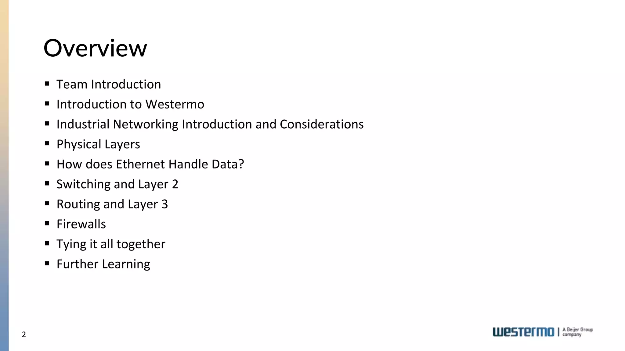
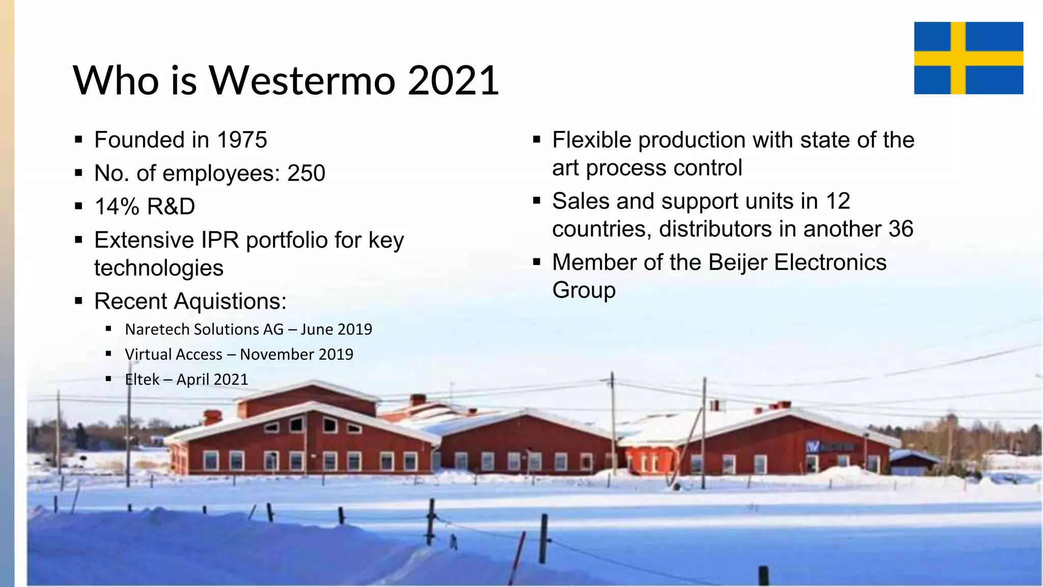
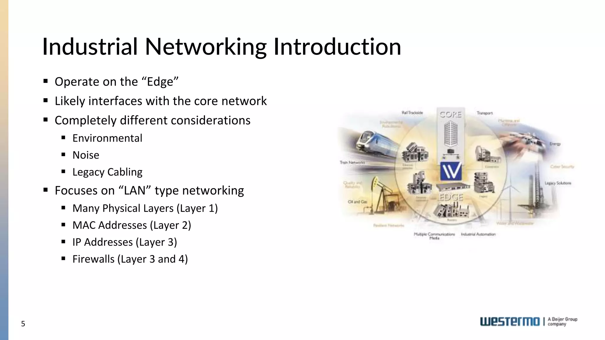
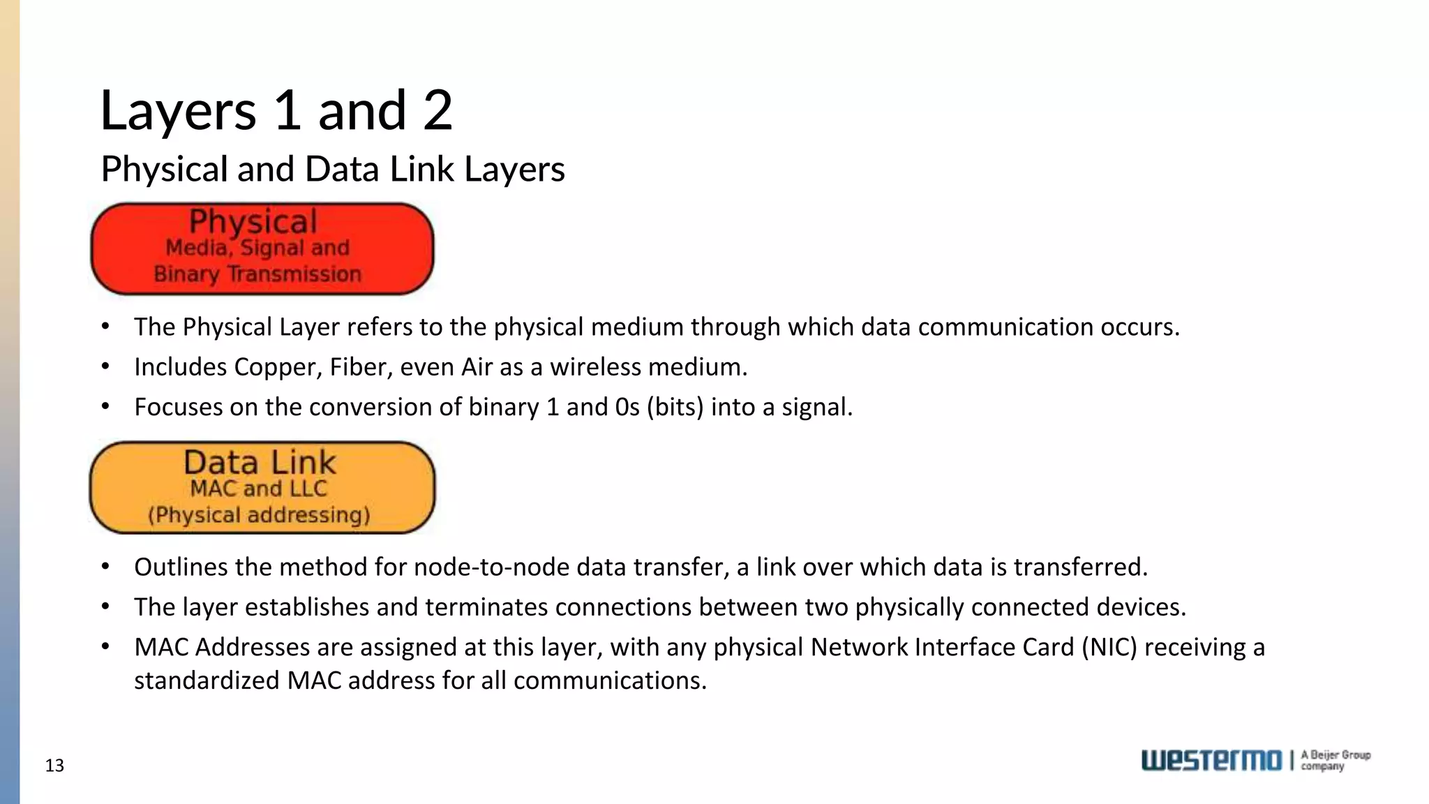
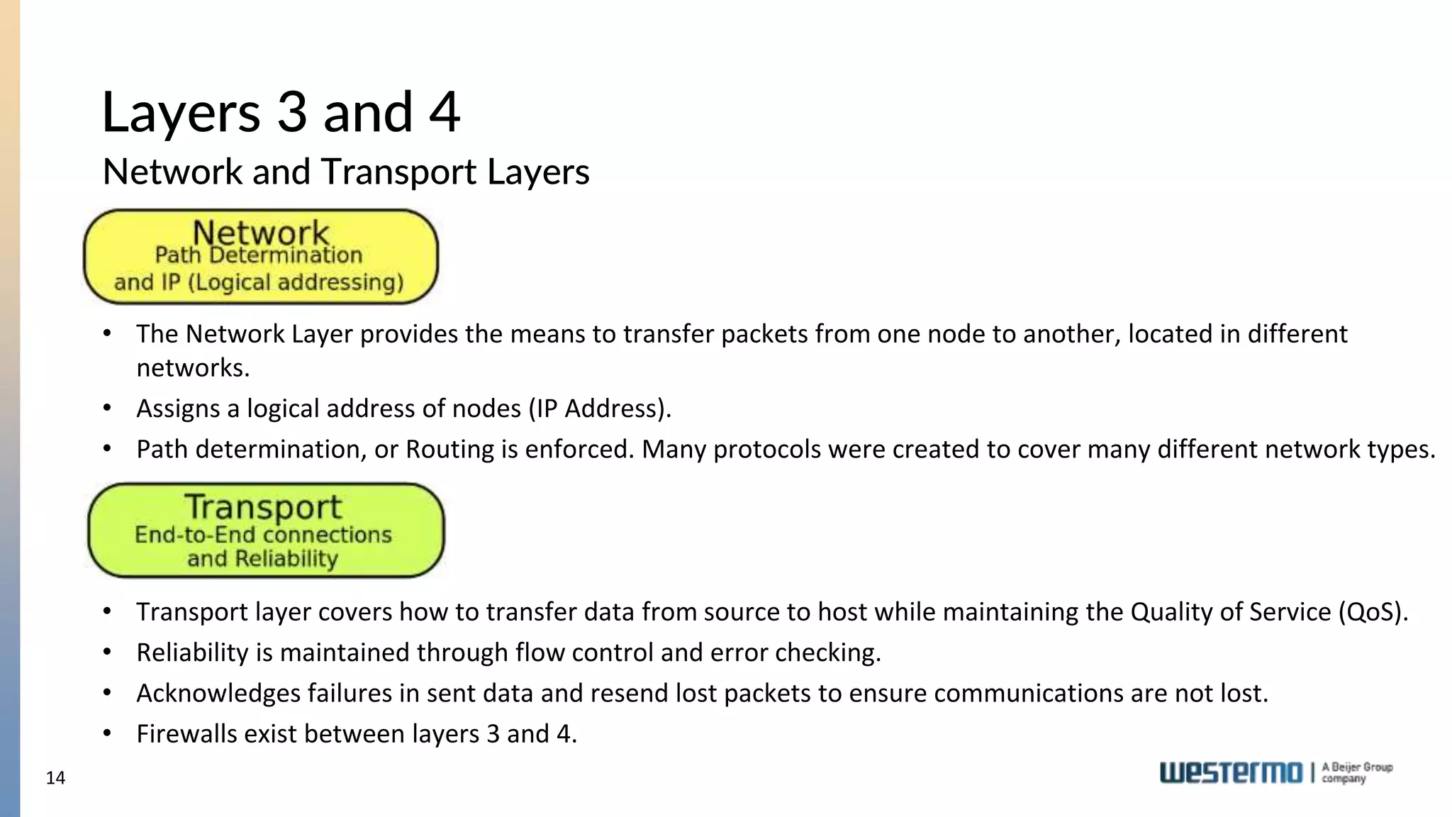
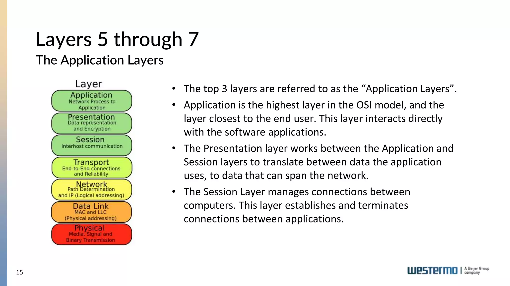
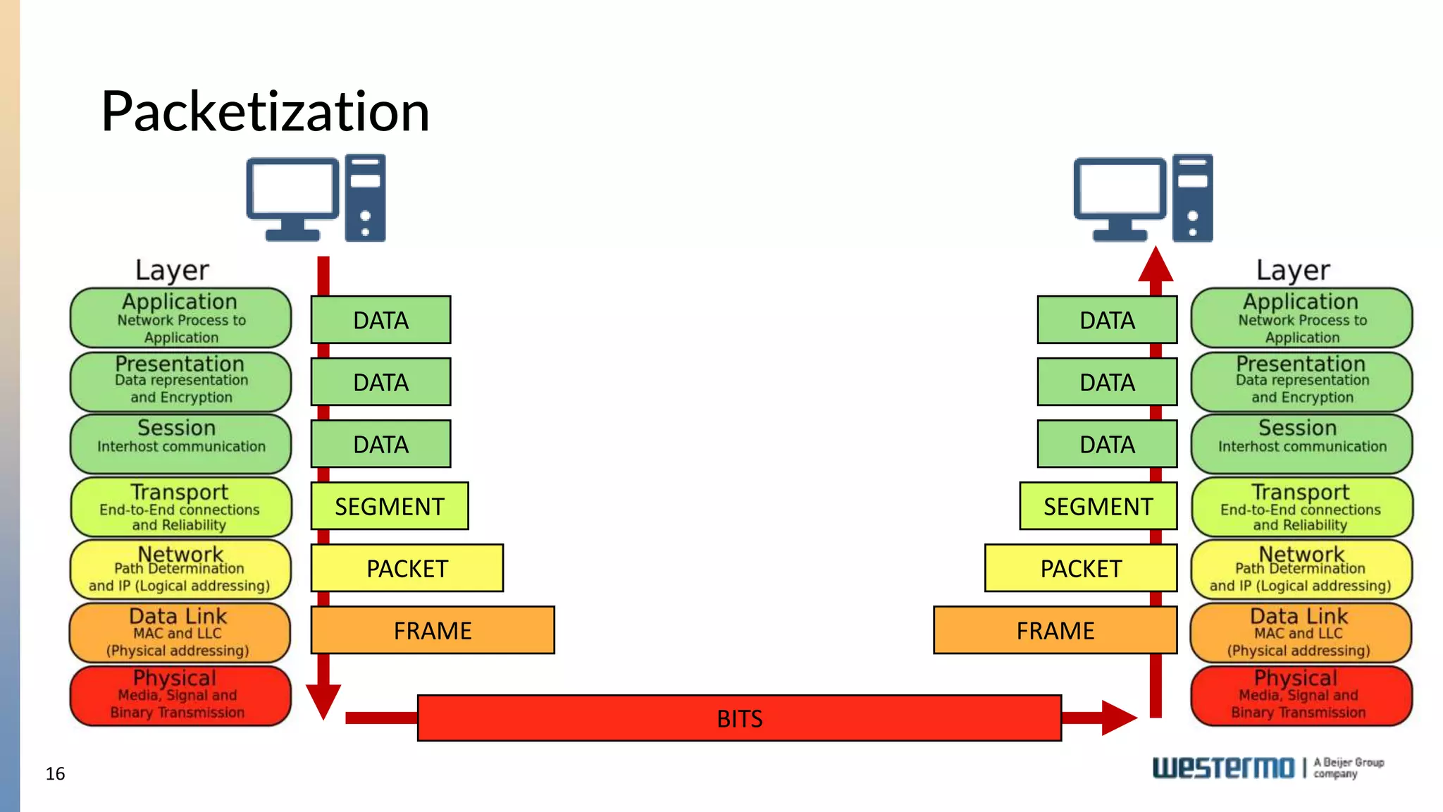
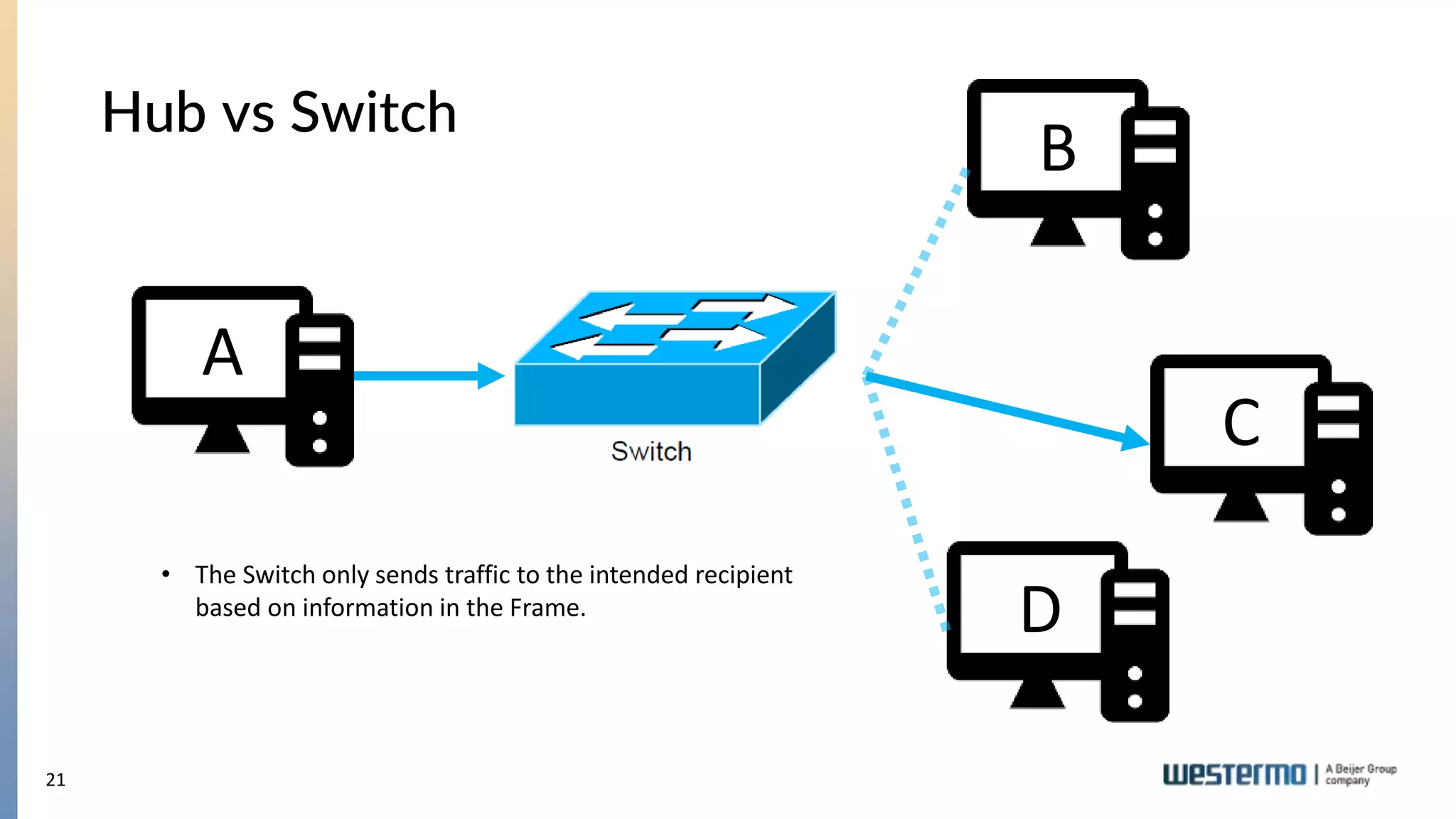
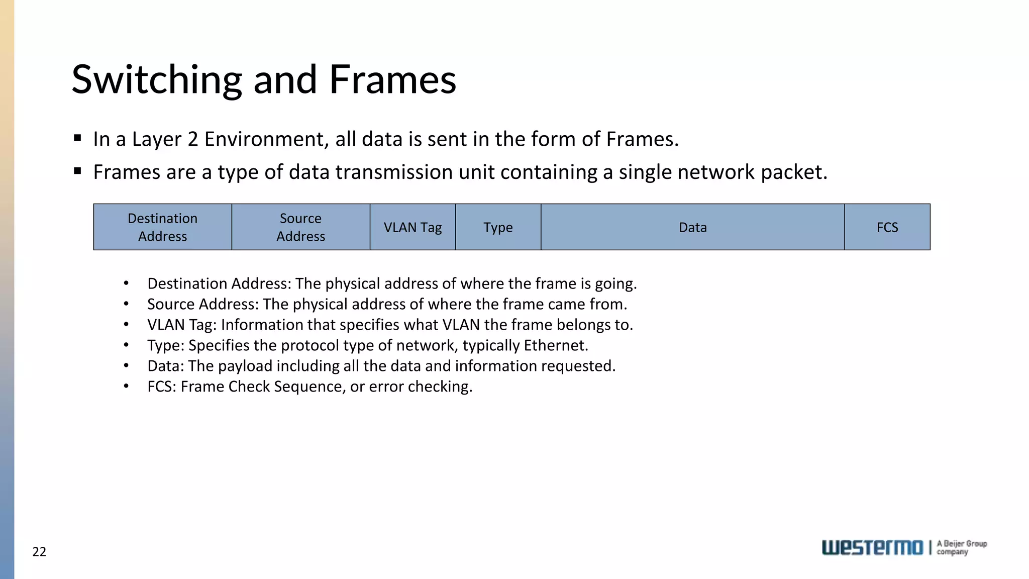
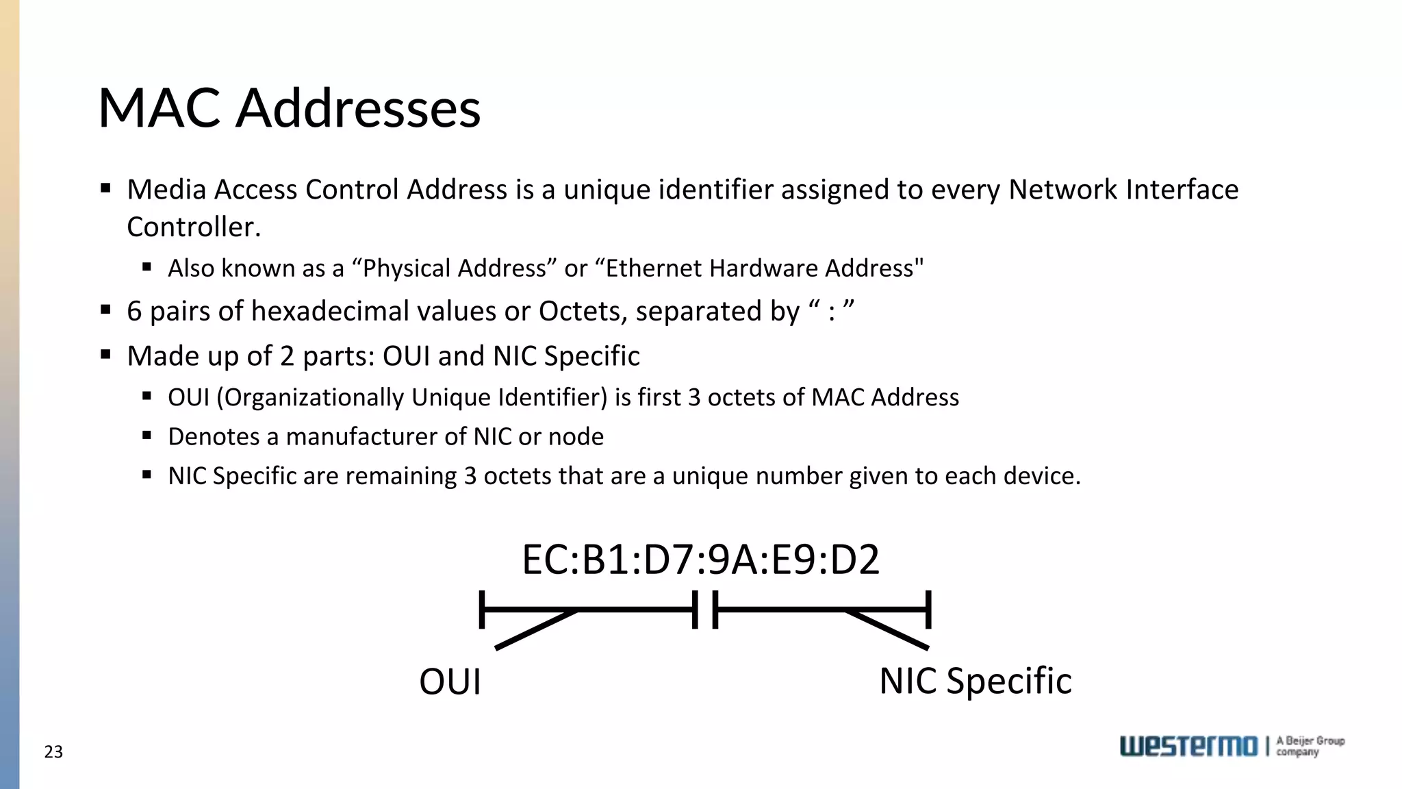
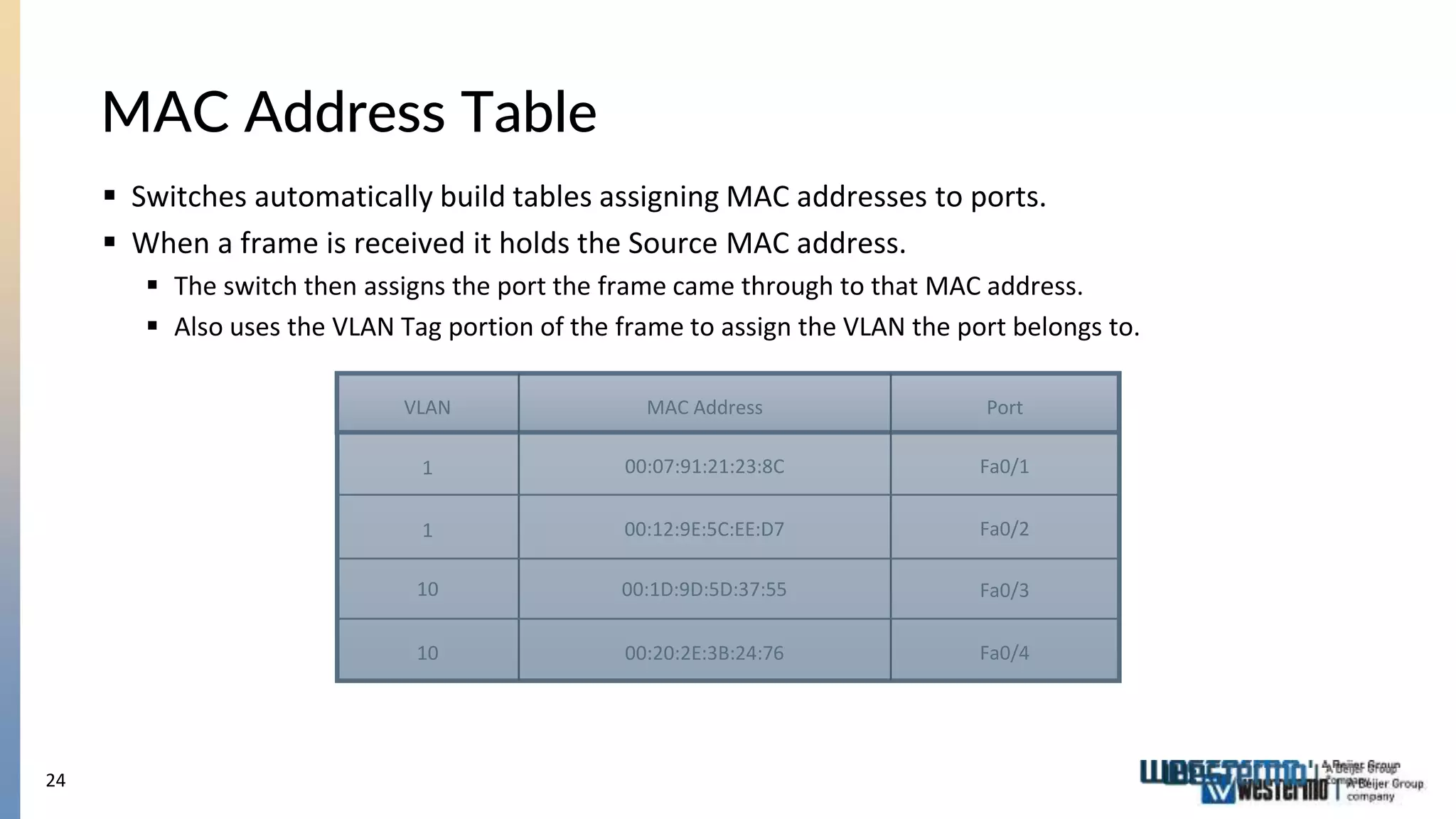
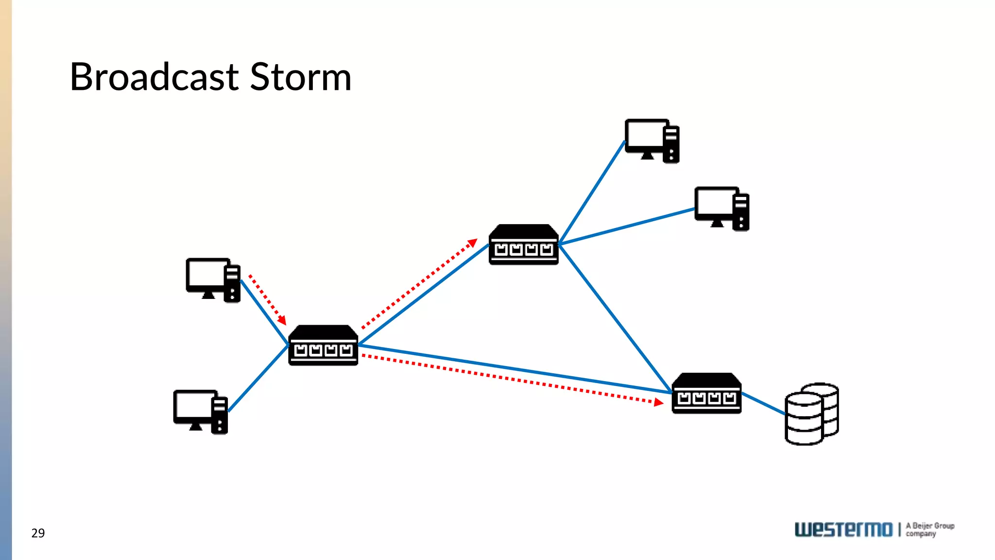
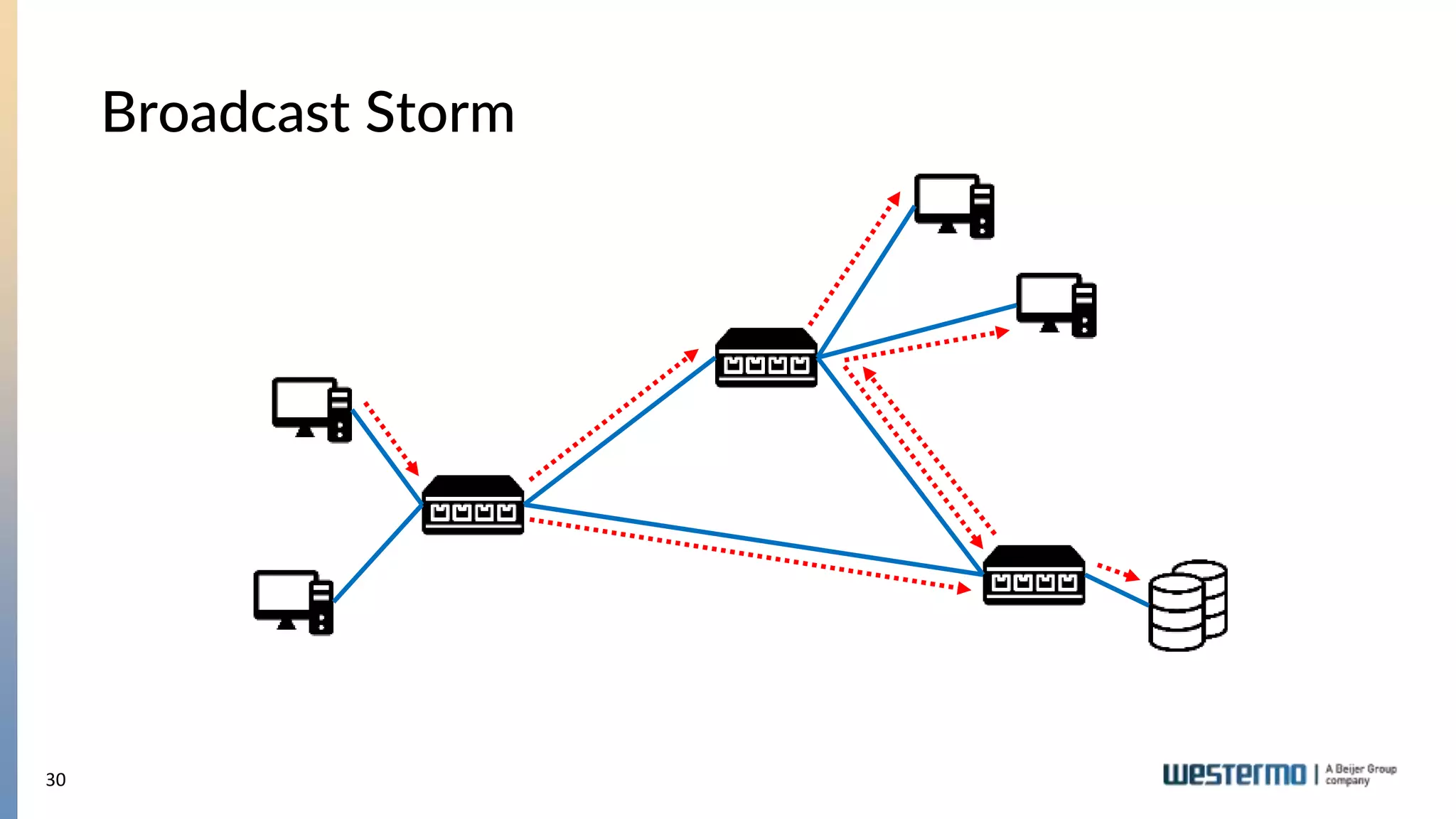
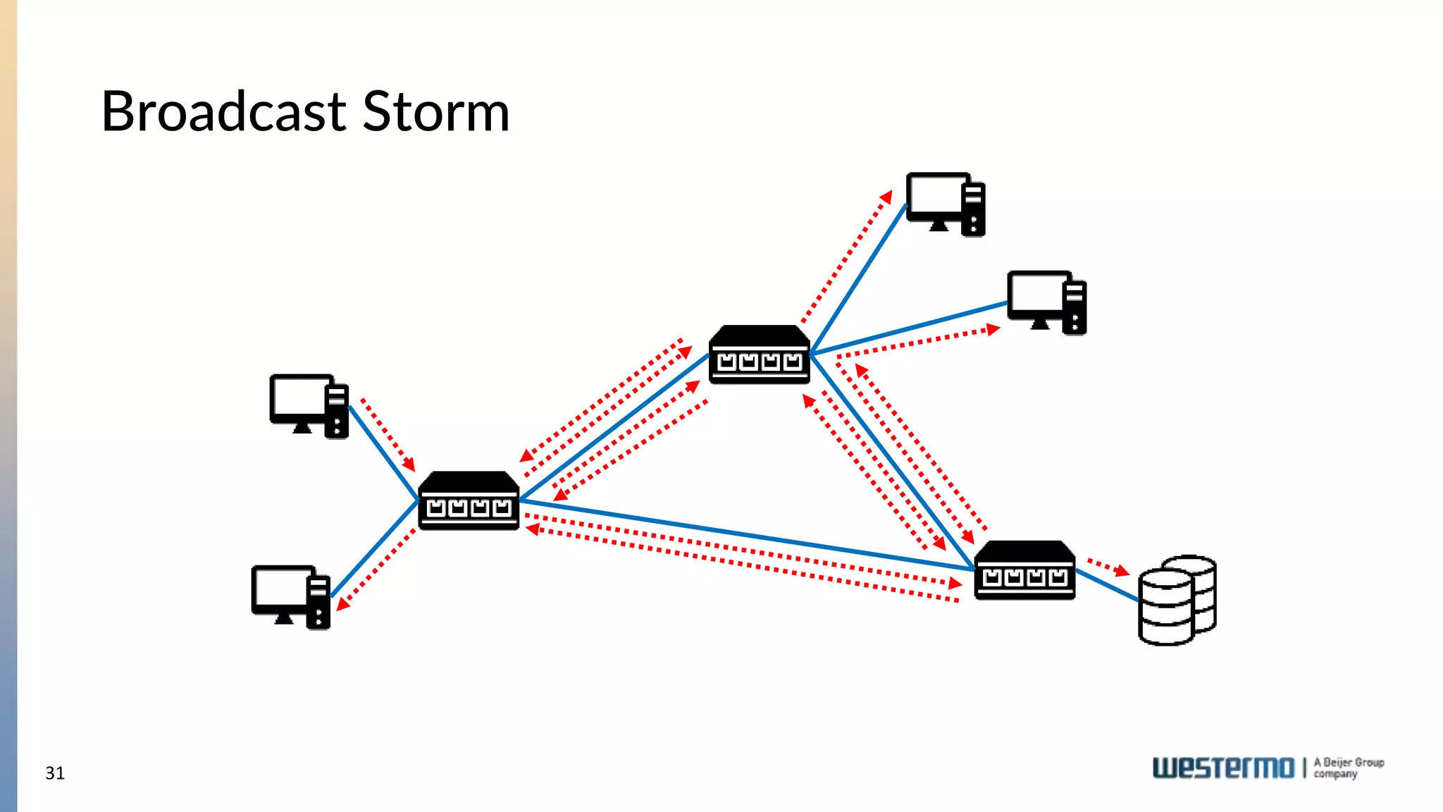
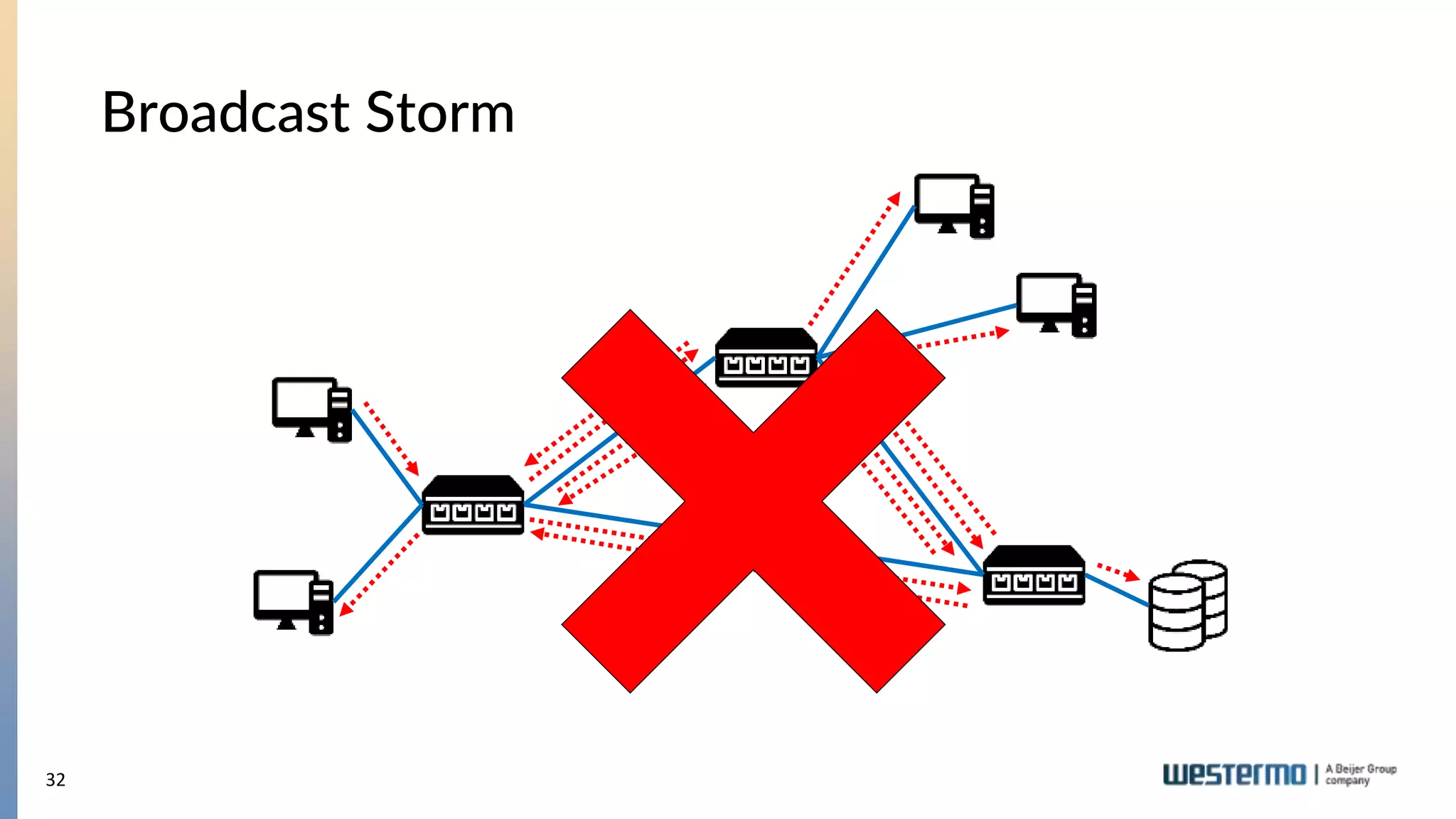

The document provides an overview of Ethernet networking, covering key concepts such as industrial networking, physical layers, data handling, switching, routing, and firewalls. It introduces Westermo, its historical context, and industry presence, and discusses the importance of environmental considerations in industrial settings. Further learning opportunities and training programs offered by Westermo are also presented.


![Vibe Coding vs. Spec-Driven Development [Free Meetup]](https://cdn.slidesharecdn.com/ss_thumbnails/vibecodingvsspecdrivendevelopment-251209105622-43f455e7-thumbnail.jpg?width=640&height=640&fit=bounds)


