Downloaded 1,003 times
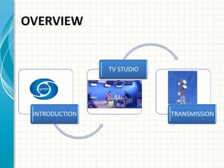
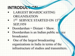
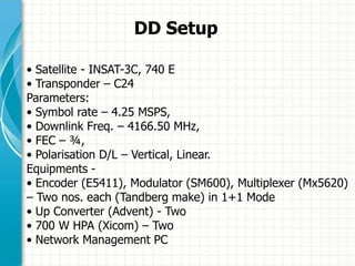


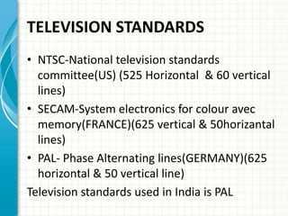


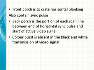
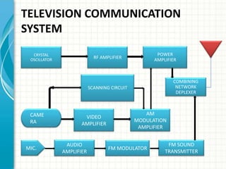


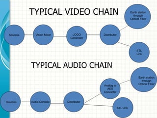

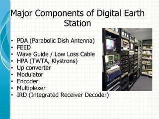
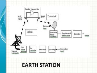

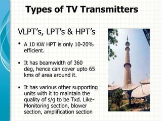
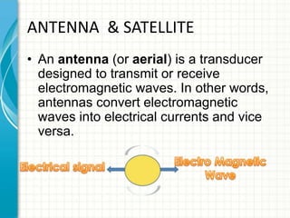


This document provides an overview of Doordarshan, the public service broadcaster of India. It discusses the history and establishment of Doordarshan, describing how it began terrestrial television broadcasts in 1959. The document outlines the key components of Doordarshan's infrastructure, including studios, transmitters, earth stations, and various television equipment. It also provides technical details on television standards, encoding, transmission systems, and the role of different types of antennas and satellites in broadcast distribution.