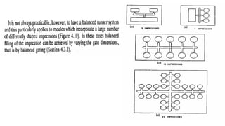
This document discusses various aspects of injection mold design including:
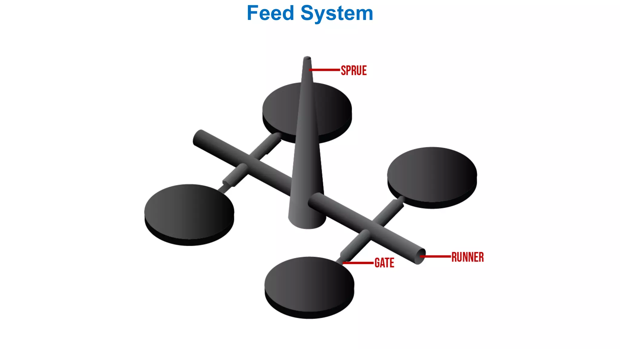
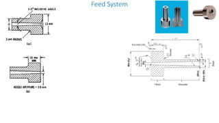
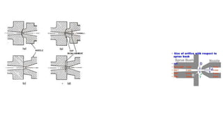
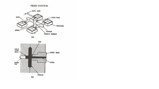
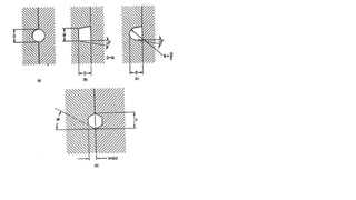
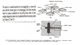
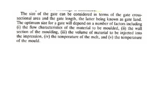
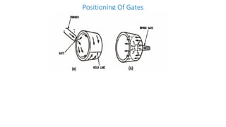
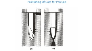
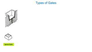
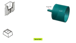
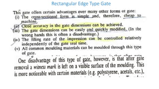
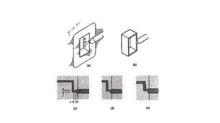
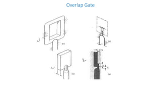
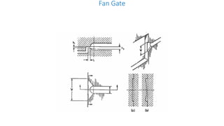
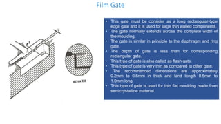
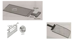
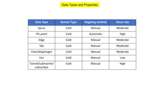
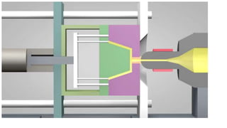
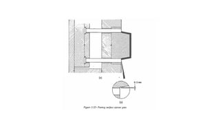
1. Feed systems, runner designs, and types of gates like sprue gates, edge gates, overlap gates, and pin gates.
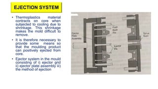
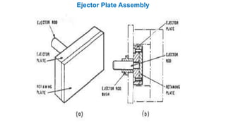
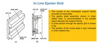
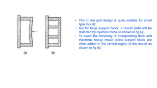
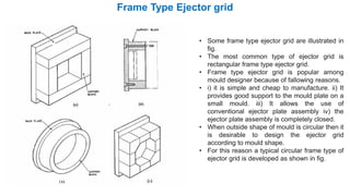
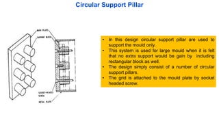
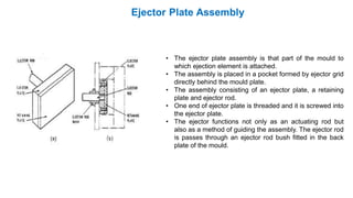
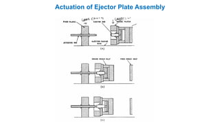
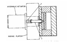
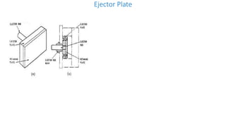
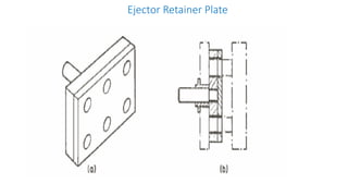
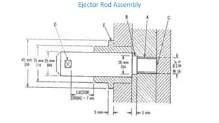
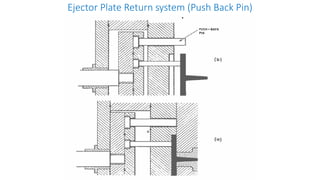
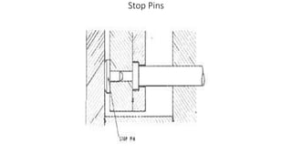
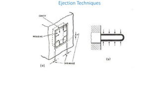
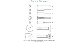
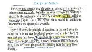
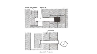
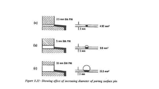
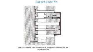
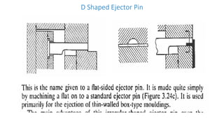
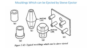
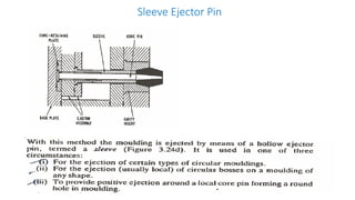
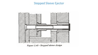
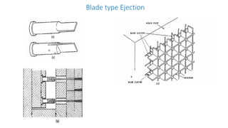
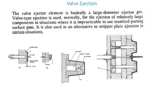
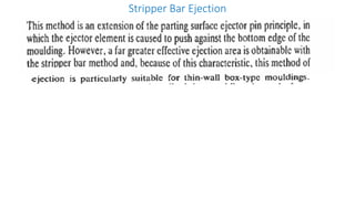
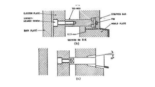
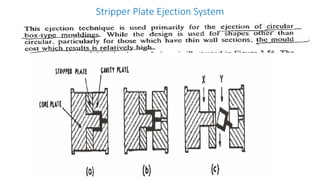
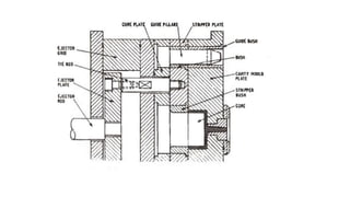
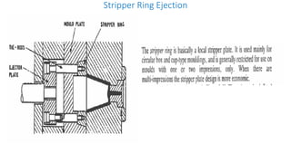
2. Ejection systems including ejector grids, ejector plate assemblies, and different ejection techniques like pin ejection and stripper plate ejection.
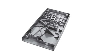
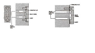
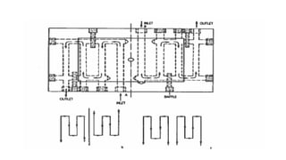
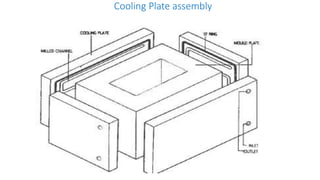
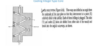
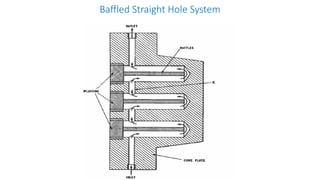
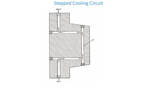
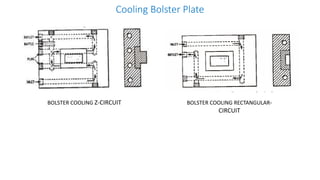
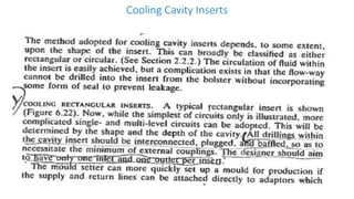
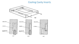
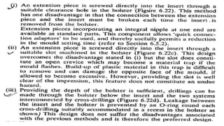
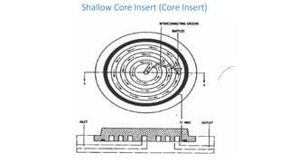
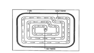
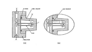
3. Cooling systems for molds including cooling of cavity plates, cores, bolster plates, and cavity inserts to efficiently cool molded parts.