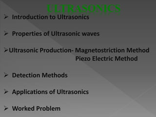
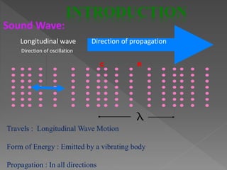
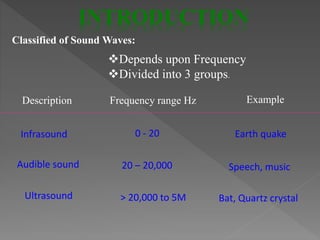
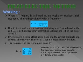
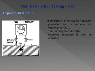
This document discusses ultrasonics and its applications. It begins with an introduction to ultrasonic waves, including their properties and production methods such as magnetostriction and piezoelectric methods. Next, it describes common detection methods and applications of ultrasonics such as non-destructive testing to detect flaws in metals using ultrasonic beams. In closing, it provides a brief example of using ultrasonics for non-destructive testing to examine reflected echoes on an oscilloscope and detect flaws in materials.
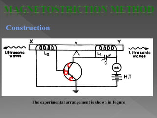


![ultrasonic interferometer pankaj yadav (4)_FPI[1][1].pptx](https://cdn.slidesharecdn.com/ss_thumbnails/ultrasonicinterferometerpankajyadav4fpi11-221220043423-973d26b3-thumbnail.jpg?width=640&height=640&fit=bounds)


