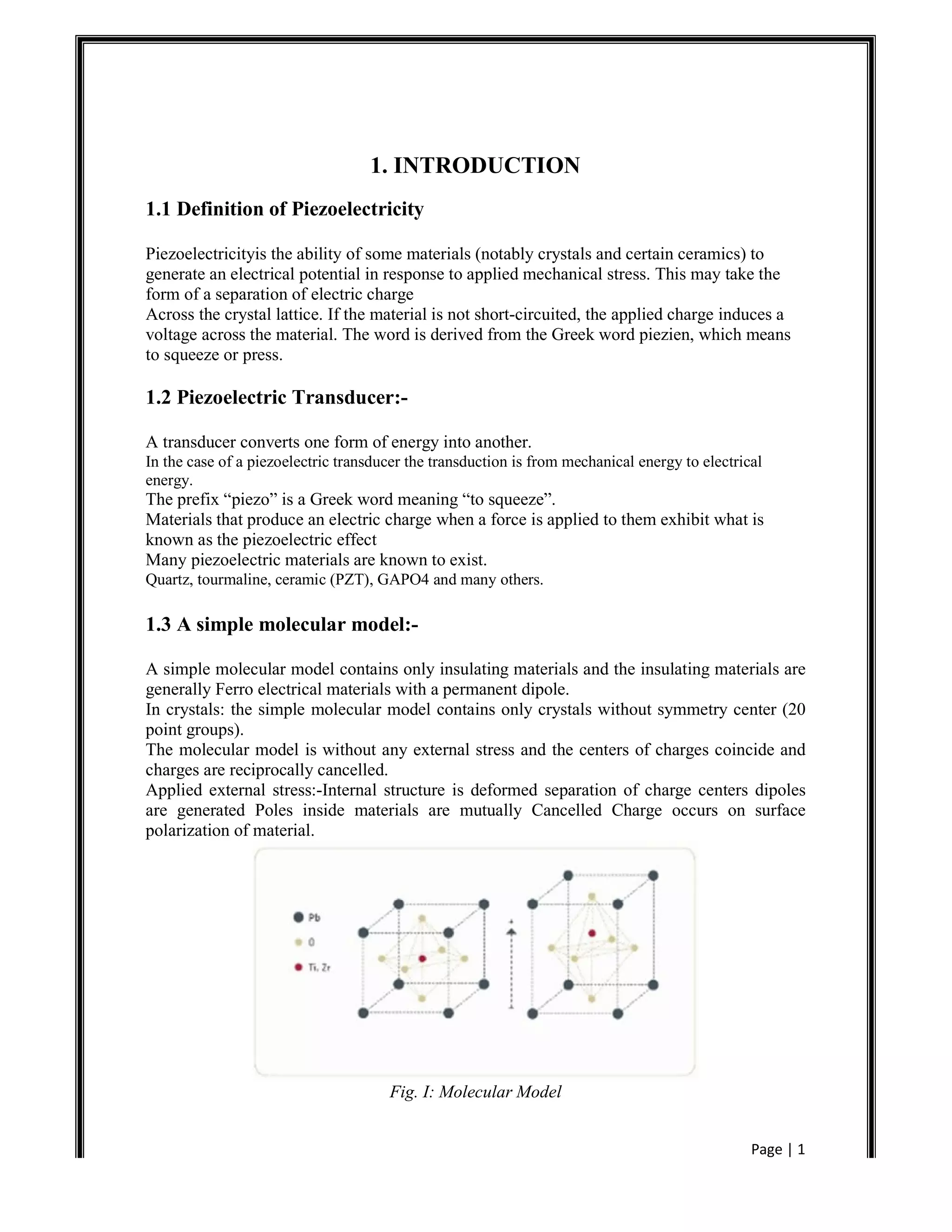
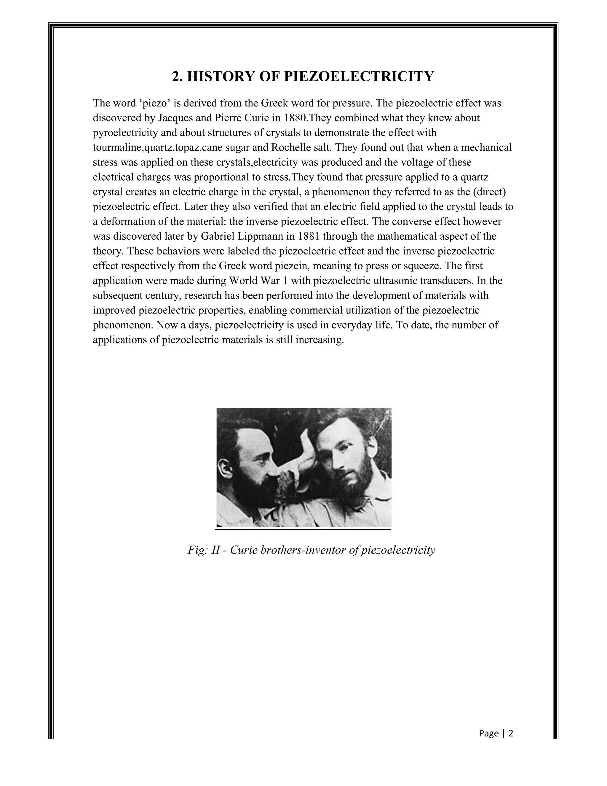
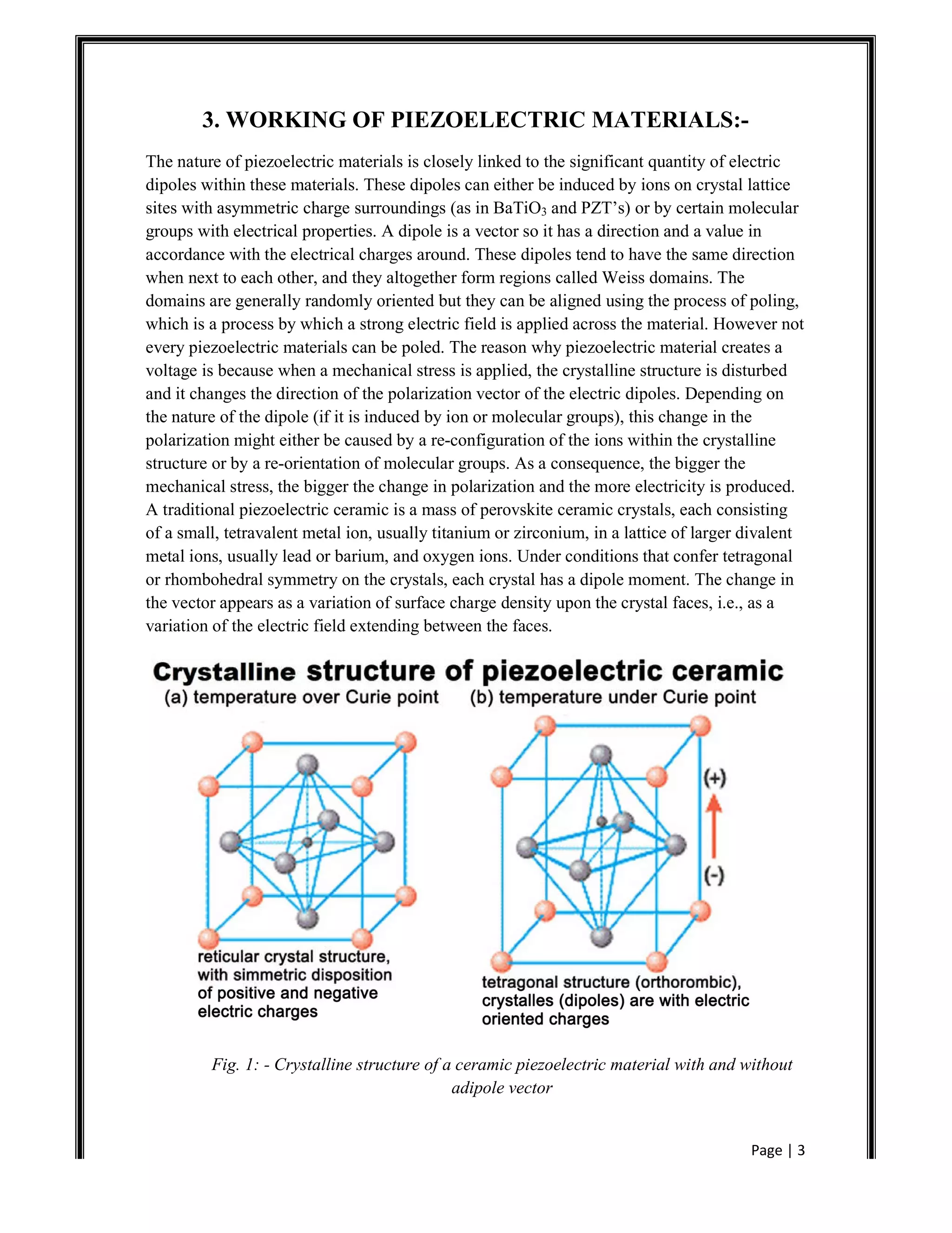
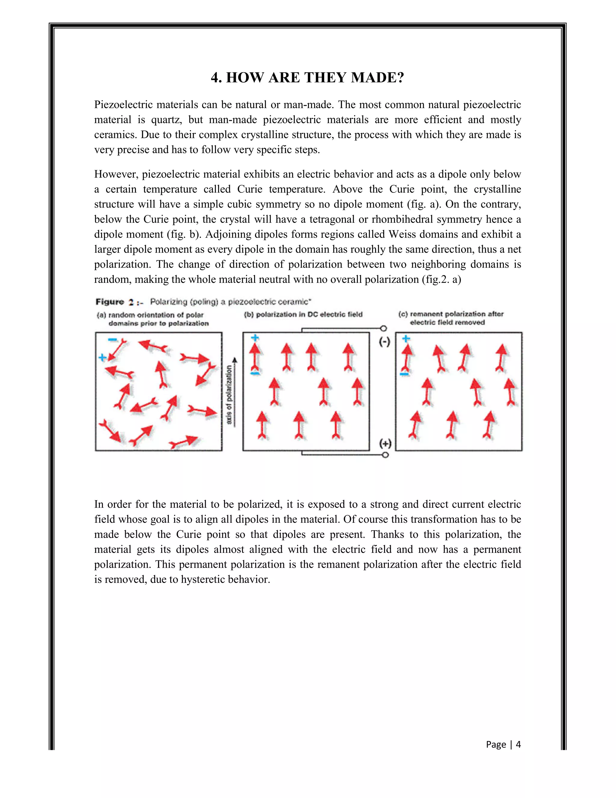
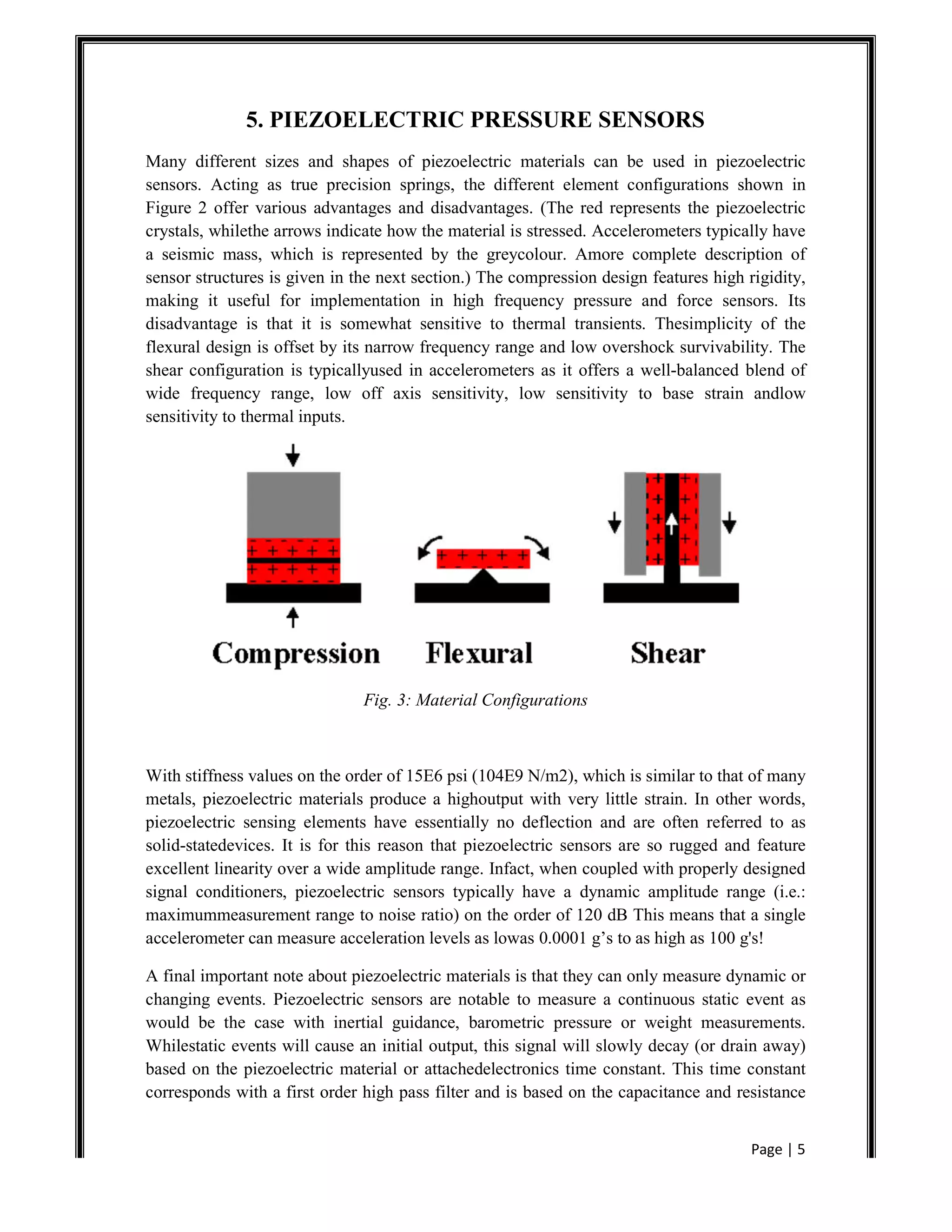
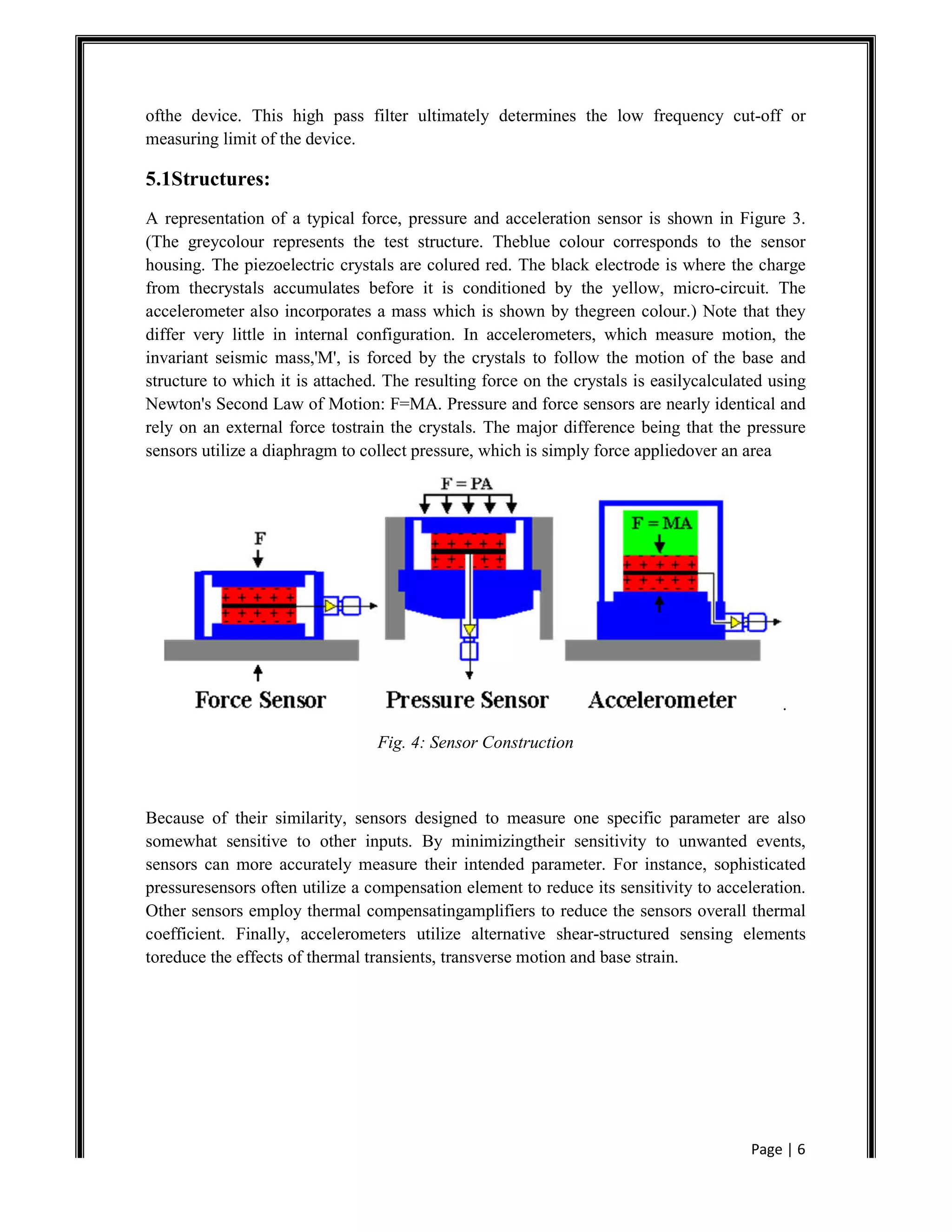
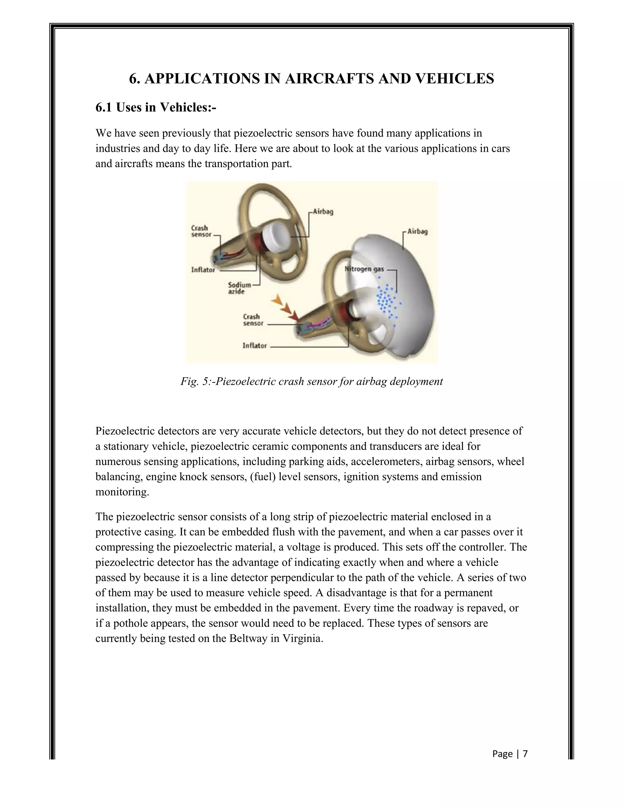
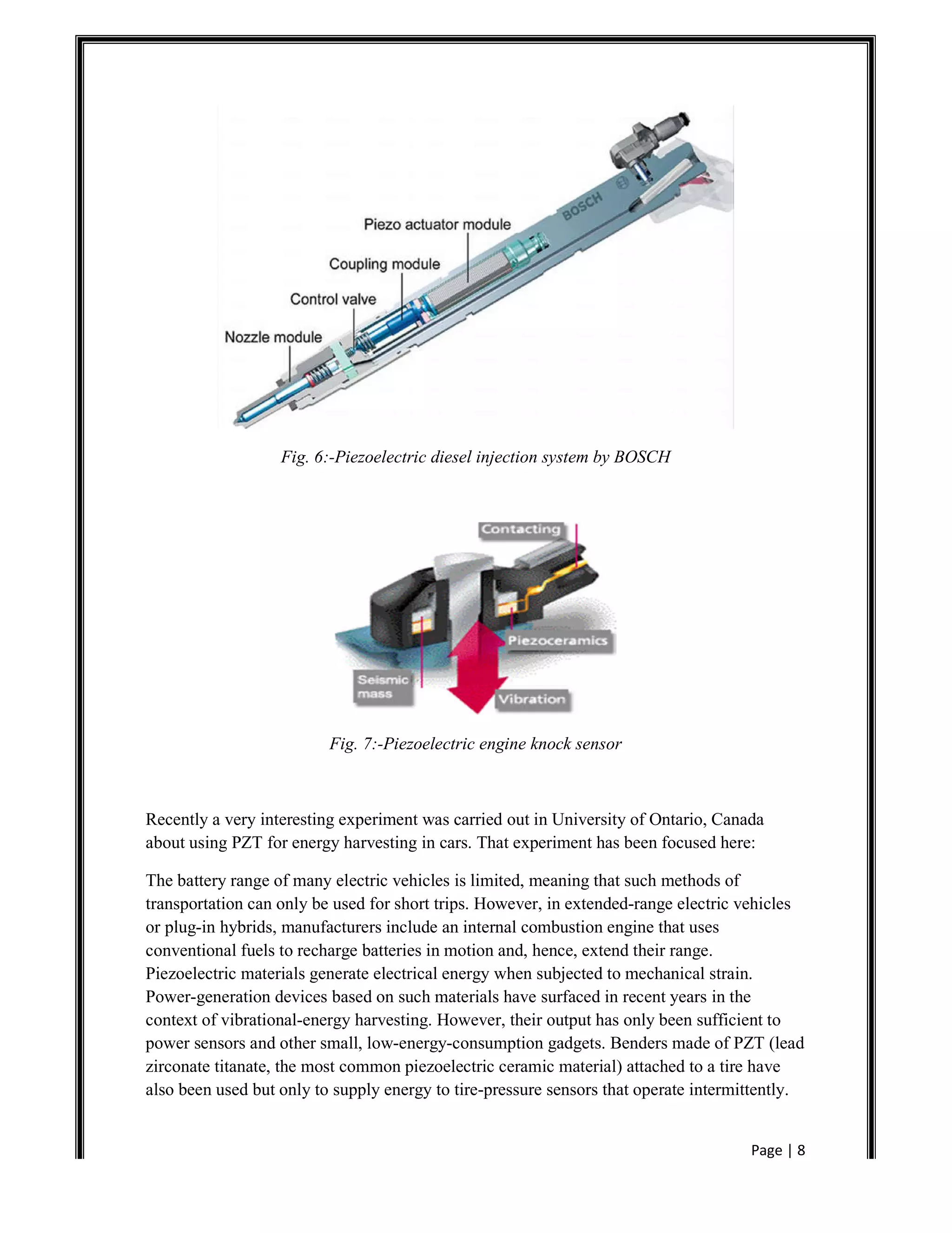
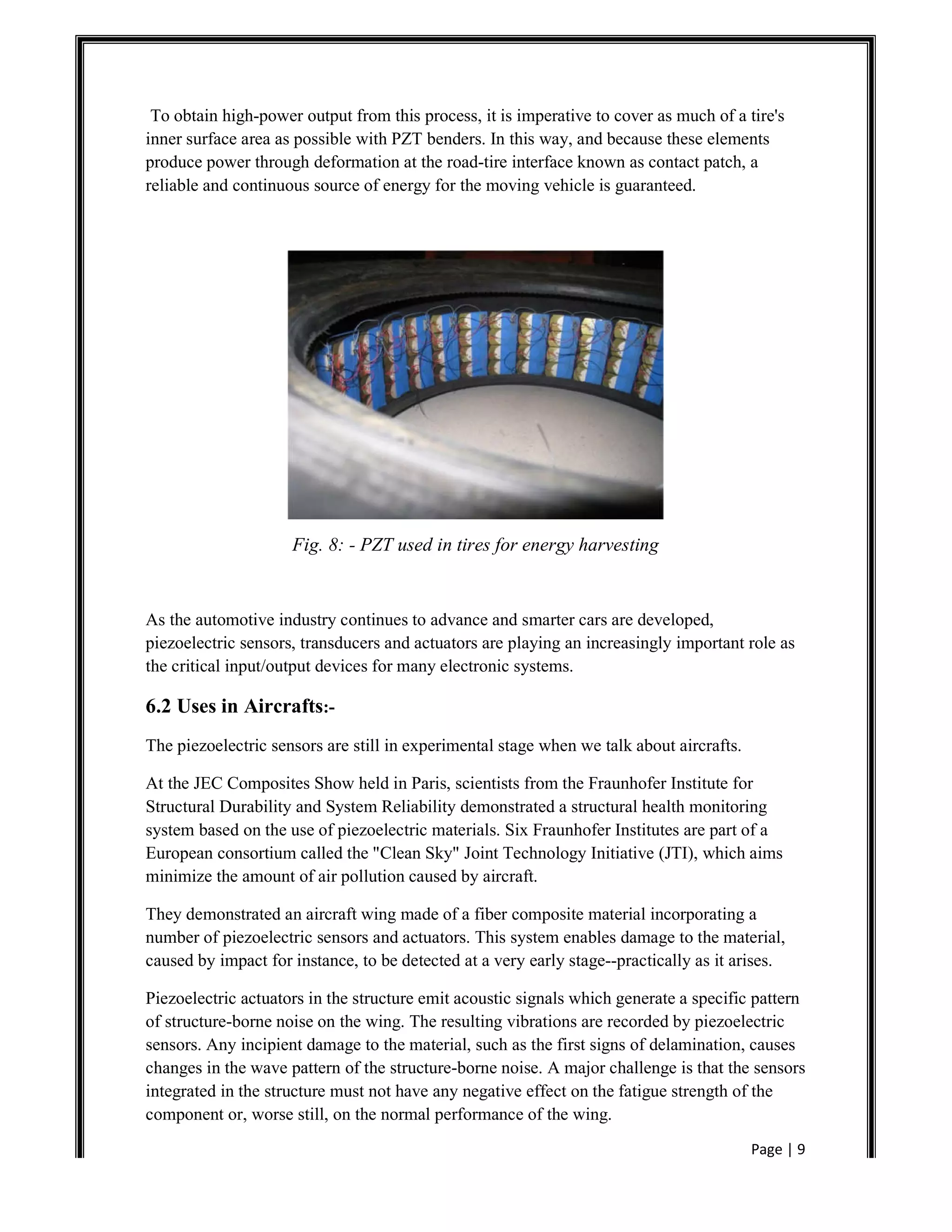
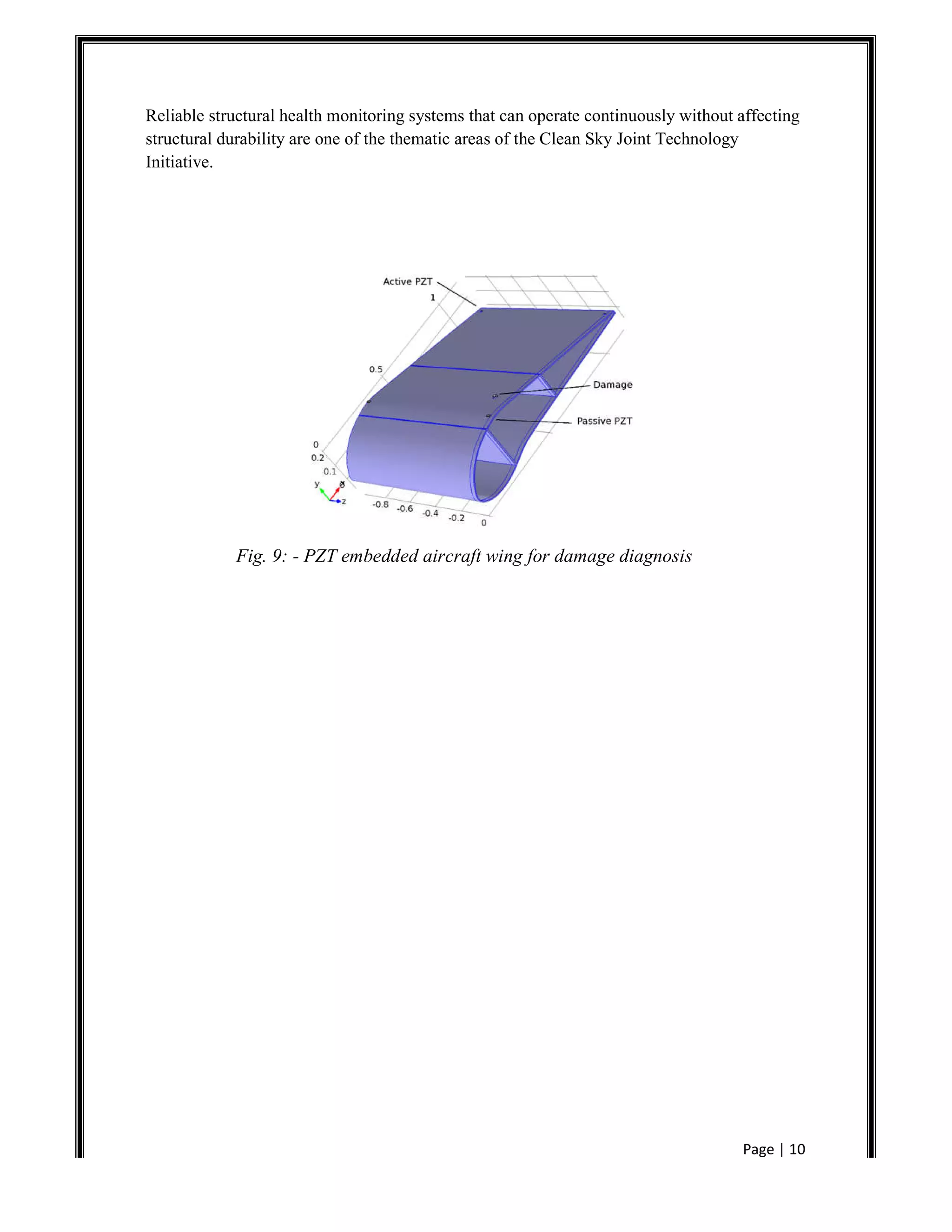
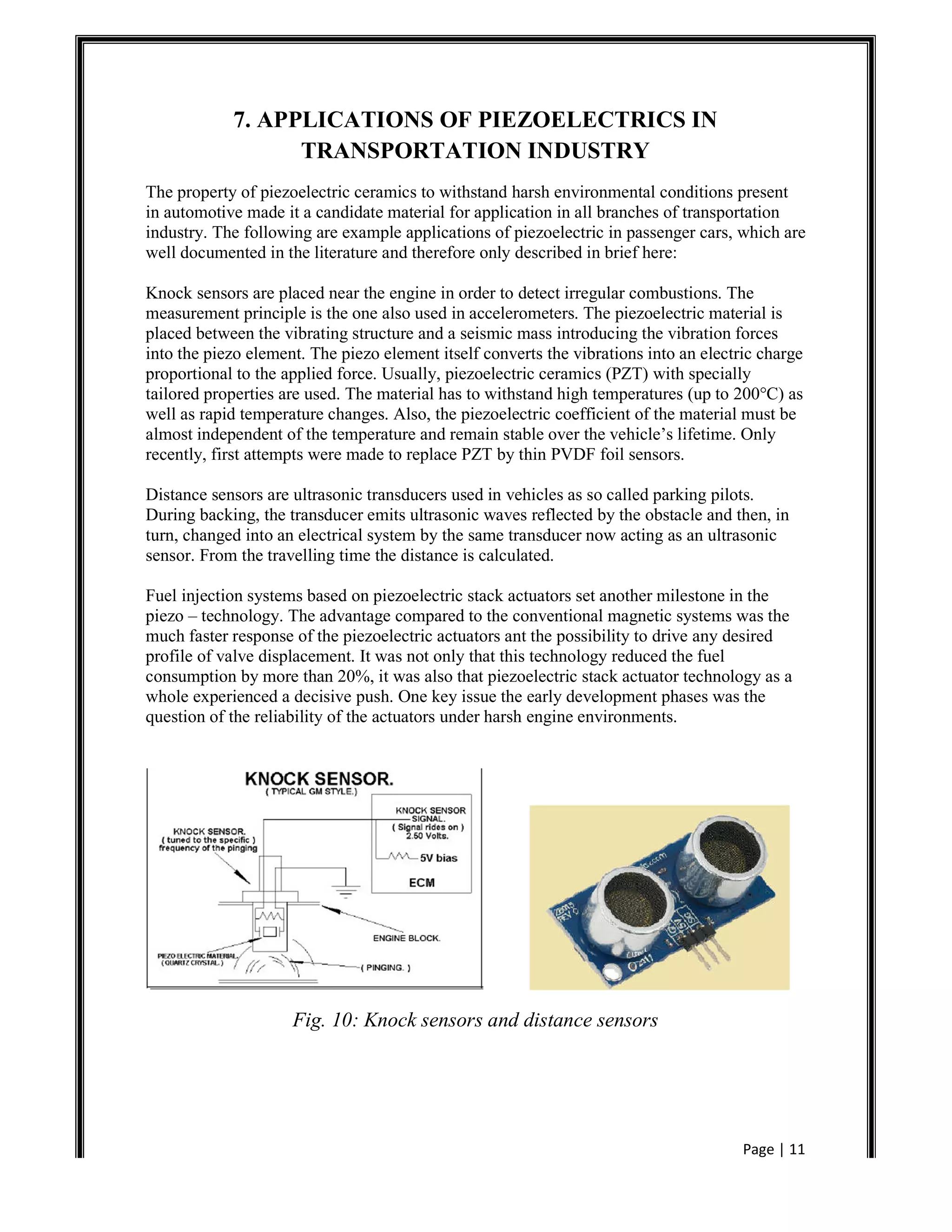
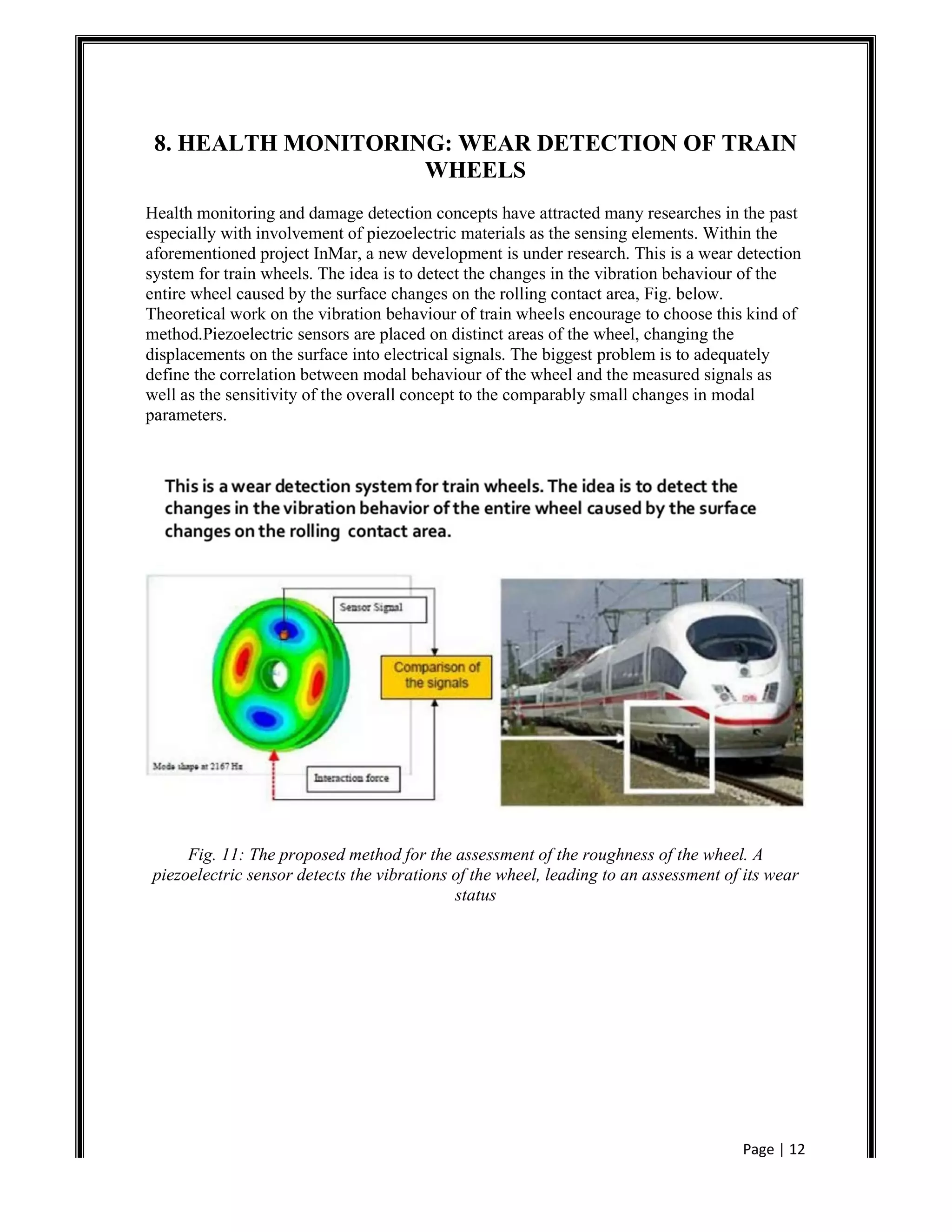
Page | 1
1. INTRODUCTION
1.1 Definition of Piezoelectricity
Piezoelectricityis the ability of some materials (notably crystals and certain ceramics) to
generate an electrical potential in response to applied mechanical stress. This may take the
form of a separation of electric charge
Across the crystal lattice. If the material is not short-circuited, the applied charge induces a
voltage across the material. The word is derived from the Greek word piezien, which means
to squeeze or press.
1.2 Piezoelectric Transducer:-
A transducer converts one form of energy into another.
In the case of a piezoelectric transducer the transduction is from mechanical energy to electrical
energy.
The prefix “piezo” is a Greek word meaning “to squeeze”.
Materials that produce an electric charge when a force is applied to them exhibit what is
known as the piezoelectric effect
Many piezoelectric materials are known to exist.
Quartz, tourmaline, ceramic (PZT), GAPO4 and many others.
1.3 A simple molecular model:-
A simple molecular model contains only insulating materials and the insulating materials are
generally Ferro electrical materials with a permanent dipole.
In crystals: the simple molecular model contains only crystals without symmetry center (20
point groups).
The molecular model is without any external stress and the centers of charges coincide and
charges are reciprocally cancelled.
Applied external stress:-Internal structure is deformed separation of charge centers dipoles
are generated Poles inside materials are mutually Cancelled Charge occurs on surface
polarization of material.
Fig. I: Molecular Model
Page | 2
2. HISTORY OF PIEZOELECTRICITY
The word ‘piezo’ is derived from the Greek word for pressure. The piezoelectric effect was
discovered by Jacques and Pierre Curie in 1880.They combined what they knew about
pyroelectricity and about structures of crystals to demonstrate the effect with
tourmaline,quartz,topaz,cane sugar and Rochelle salt. They found out that when a mechanical
stress was applied on these crystals,electricity was produced and the voltage of these
electrical charges was proportional to stress.They found that pressure applied to a quartz
crystal creates an electric charge in the crystal, a phenomenon they referred to as the (direct)
piezoelectric effect. Later they also verified that an electric field applied to the crystal leads to
a deformation of the material: the inverse piezoelectric effect. The converse effect however
was discovered later by Gabriel Lippmann in 1881 through the mathematical aspect of the
theory. These behaviors were labeled the piezoelectric effect and the inverse piezoelectric
effect respectively from the Greek word piezein, meaning to press or squeeze. The first
application were made during World War 1 with piezoelectric ultrasonic transducers. In the
subsequent century, research has been performed into the development of materials with
improved piezoelectric properties, enabling commercial utilization of the piezoelectric
phenomenon. Now a days, piezoelectricity is used in everyday life. To date, the number of
applications of piezoelectric materials is still increasing.
Fig: II - Curie brothers-inventor of piezoelectricity
Page | 3
3. WORKING OF PIEZOELECTRIC MATERIALS:-
The nature of piezoelectric materials is closely linked to the significant quantity of electric
dipoles within these materials. These dipoles can either be induced by ions on crystal lattice
sites with asymmetric charge surroundings (as in BaTiO3 and PZT’s) or by certain molecular
groups with electrical properties. A dipole is a vector so it has a direction and a value in
accordance with the electrical charges around. These dipoles tend to have the same direction
when next to each other, and they altogether form regions called Weiss domains. The
domains are generally randomly oriented but they can be aligned using the process of poling,
which is a process by which a strong electric field is applied across the material. However not
every piezoelectric materials can be poled. The reason why piezoelectric material creates a
voltage is because when a mechanical stress is applied, the crystalline structure is disturbed
and it changes the direction of the polarization vector of the electric dipoles. Depending on
the nature of the dipole (if it is induced by ion or molecular groups), this change in the
polarization might either be caused by a re-configuration of the ions within the crystalline
structure or by a re-orientation of molecular groups. As a consequence, the bigger the
mechanical stress, the bigger the change in polarization and the more electricity is produced.
A traditional piezoelectric ceramic is a mass of perovskite ceramic crystals, each consisting
of a small, tetravalent metal ion, usually titanium or zirconium, in a lattice of larger divalent
metal ions, usually lead or barium, and oxygen ions. Under conditions that confer tetragonal
or rhombohedral symmetry on the crystals, each crystal has a dipole moment. The change in
the vector appears as a variation of surface charge density upon the crystal faces, i.e., as a
variation of the electric field extending between the faces.
Fig. 1: - Crystalline structure of a ceramic piezoelectric material with and without
adipole vector
Page | 4
4. HOW ARE THEY MADE?
Piezoelectric materials can be natural or man-made. The most common natural piezoelectric
material is quartz, but man-made piezoelectric materials are more efficient and mostly
ceramics. Due to their complex crystalline structure, the process with which they are made is
very precise and has to follow very specific steps.
However, piezoelectric material exhibits an electric behavior and acts as a dipole only below
a certain temperature called Curie temperature. Above the Curie point, the crystalline
structure will have a simple cubic symmetry so no dipole moment (fig. a). On the contrary,
below the Curie point, the crystal will have a tetragonal or rhombihedral symmetry hence a
dipole moment (fig. b). Adjoining dipoles forms regions called Weiss domains and exhibit a
larger dipole moment as every dipole in the domain has roughly the same direction, thus a net
polarization. The change of direction of polarization between two neighboring domains is
random, making the whole material neutral with no overall polarization (fig.2. a)
In order for the material to be polarized, it is exposed to a strong and direct current electric
field whose goal is to align all dipoles in the material. Of course this transformation has to be
made below the Curie point so that dipoles are present. Thanks to this polarization, the
material gets its dipoles almost aligned with the electric field and now has a permanent
polarization. This permanent polarization is the remanent polarization after the electric field
is removed, due to hysteretic behavior.
Page | 5
5. PIEZOELECTRIC PRESSURE SENSORS
Many different sizes and shapes of piezoelectric materials can be used in piezoelectric
sensors. Acting as true precision springs, the different element configurations shown in
Figure 2 offer various advantages and disadvantages. (The red represents the piezoelectric
crystals, whilethe arrows indicate how the material is stressed. Accelerometers typically have
a seismic mass, which is represented by the greycolour. Amore complete description of
sensor structures is given in the next section.) The compression design features high rigidity,
making it useful for implementation in high frequency pressure and force sensors. Its
disadvantage is that it is somewhat sensitive to thermal transients. Thesimplicity of the
flexural design is offset by its narrow frequency range and low overshock survivability. The
shear configuration is typicallyused in accelerometers as it offers a well-balanced blend of
wide frequency range, low off axis sensitivity, low sensitivity to base strain andlow
sensitivity to thermal inputs.
Fig. 3: Material Configurations
With stiffness values on the order of 15E6 psi (104E9 N/m2), which is similar to that of many
metals, piezoelectric materials produce a highoutput with very little strain. In other words,
piezoelectric sensing elements have essentially no deflection and are often referred to as
solid-statedevices. It is for this reason that piezoelectric sensors are so rugged and feature
excellent linearity over a wide amplitude range. Infact, when coupled with properly designed
signal conditioners, piezoelectric sensors typically have a dynamic amplitude range (i.e.:
maximummeasurement range to noise ratio) on the order of 120 dB This means that a single
accelerometer can measure acceleration levels as lowas 0.0001 g’s to as high as 100 g's!
A final important note about piezoelectric materials is that they can only measure dynamic or
changing events. Piezoelectric sensors are notable to measure a continuous static event as
would be the case with inertial guidance, barometric pressure or weight measurements.
Whilestatic events will cause an initial output, this signal will slowly decay (or drain away)
based on the piezoelectric material or attachedelectronics time constant. This time constant
corresponds with a first order high pass filter and is based on the capacitance and resistance
Page | 6
ofthe device. This high pass filter ultimately determines the low frequency cut-off or
measuring limit of the device.
5.1Structures:
A representation of a typical force, pressure and acceleration sensor is shown in Figure 3.
(The greycolour represents the test structure. Theblue colour corresponds to the sensor
housing. The piezoelectric crystals are colured red. The black electrode is where the charge
from thecrystals accumulates before it is conditioned by the yellow, micro-circuit. The
accelerometer also incorporates a mass which is shown by thegreen colour.) Note that they
differ very little in internal configuration. In accelerometers, which measure motion, the
invariant seismic mass,'M', is forced by the crystals to follow the motion of the base and
structure to which it is attached. The resulting force on the crystals is easilycalculated using
Newton's Second Law of Motion: F=MA. Pressure and force sensors are nearly identical and
rely on an external force tostrain the crystals. The major difference being that the pressure
sensors utilize a diaphragm to collect pressure, which is simply force appliedover an area
.
Fig. 4: Sensor Construction
Because of their similarity, sensors designed to measure one specific parameter are also
somewhat sensitive to other inputs. By minimizingtheir sensitivity to unwanted events,
sensors can more accurately measure their intended parameter. For instance, sophisticated
pressuresensors often utilize a compensation element to reduce its sensitivity to acceleration.
Other sensors employ thermal compensatingamplifiers to reduce the sensors overall thermal
coefficient. Finally, accelerometers utilize alternative shear-structured sensing elements
toreduce the effects of thermal transients, transverse motion and base strain.
Page | 7
6. APPLICATIONS IN AIRCRAFTS AND VEHICLES
6.1 Uses in Vehicles:-
We have seen previously that piezoelectric sensors have found many applications in
industries and day to day life. Here we are about to look at the various applications in cars
and aircrafts means the transportation part.
Fig. 5:-Piezoelectric crash sensor for airbag deployment
Piezoelectric detectors are very accurate vehicle detectors, but they do not detect presence of
a stationary vehicle, piezoelectric ceramic components and transducers are ideal for
numerous sensing applications, including parking aids, accelerometers, airbag sensors, wheel
balancing, engine knock sensors, (fuel) level sensors, ignition systems and emission
monitoring.
The piezoelectric sensor consists of a long strip of piezoelectric material enclosed in a
protective casing. It can be embedded flush with the pavement, and when a car passes over it
compressing the piezoelectric material, a voltage is produced. This sets off the controller. The
piezoelectric detector has the advantage of indicating exactly when and where a vehicle
passed by because it is a line detector perpendicular to the path of the vehicle. A series of two
of them may be used to measure vehicle speed. A disadvantage is that for a permanent
installation, they must be embedded in the pavement. Every time the roadway is repaved, or
if a pothole appears, the sensor would need to be replaced. These types of sensors are
currently being tested on the Beltway in Virginia.
Page | 8
Fig. 6:-Piezoelectric diesel injection system by BOSCH
Fig. 7:-Piezoelectric engine knock sensor
Recently a very interesting experiment was carried out in University of Ontario, Canada
about using PZT for energy harvesting in cars. That experiment has been focused here:
The battery range of many electric vehicles is limited, meaning that such methods of
transportation can only be used for short trips. However, in extended-range electric vehicles
or plug-in hybrids, manufacturers include an internal combustion engine that uses
conventional fuels to recharge batteries in motion and, hence, extend their range.
Piezoelectric materials generate electrical energy when subjected to mechanical strain.
Power-generation devices based on such materials have surfaced in recent years in the
context of vibrational-energy harvesting. However, their output has only been sufficient to
power sensors and other small, low-energy-consumption gadgets. Benders made of PZT (lead
zirconate titanate, the most common piezoelectric ceramic material) attached to a tire have
also been used but only to supply energy to tire-pressure sensors that operate intermittently.
Page | 9
To obtain high-power output from this process, it is imperative to cover as much of a tire's
inner surface area as possible with PZT benders. In this way, and because these elements
produce power through deformation at the road-tire interface known as contact patch, a
reliable and continuous source of energy for the moving vehicle is guaranteed.
Fig. 8: - PZT used in tires for energy harvesting
As the automotive industry continues to advance and smarter cars are developed,
piezoelectric sensors, transducers and actuators are playing an increasingly important role as
the critical input/output devices for many electronic systems.
6.2 Uses in Aircrafts:-
The piezoelectric sensors are still in experimental stage when we talk about aircrafts.
At the JEC Composites Show held in Paris, scientists from the Fraunhofer Institute for
Structural Durability and System Reliability demonstrated a structural health monitoring
system based on the use of piezoelectric materials. Six Fraunhofer Institutes are part of a
European consortium called the "Clean Sky" Joint Technology Initiative (JTI), which aims
minimize the amount of air pollution caused by aircraft.
They demonstrated an aircraft wing made of a fiber composite material incorporating a
number of piezoelectric sensors and actuators. This system enables damage to the material,
caused by impact for instance, to be detected at a very early stage--practically as it arises.
Piezoelectric actuators in the structure emit acoustic signals which generate a specific pattern
of structure-borne noise on the wing. The resulting vibrations are recorded by piezoelectric
sensors. Any incipient damage to the material, such as the first signs of delamination, causes
changes in the wave pattern of the structure-borne noise. A major challenge is that the sensors
integrated in the structure must not have any negative effect on the fatigue strength of the
component or, worse still, on the normal performance of the wing.
Page | 10
Reliable structural health monitoring systems that can operate continuously without affecting
structural durability are one of the thematic areas of the Clean Sky Joint Technology
Initiative.
Fig. 9: - PZT embedded aircraft wing for damage diagnosis
Page | 11
7. APPLICATIONS OF PIEZOELECTRICS IN
TRANSPORTATION INDUSTRY
The property of piezoelectric ceramics to withstand harsh environmental conditions present
in automotive made it a candidate material for application in all branches of transportation
industry. The following are example applications of piezoelectric in passenger cars, which are
well documented in the literature and therefore only described in brief here:
Knock sensors are placed near the engine in order to detect irregular combustions. The
measurement principle is the one also used in accelerometers. The piezoelectric material is
placed between the vibrating structure and a seismic mass introducing the vibration forces
into the piezo element. The piezo element itself converts the vibrations into an electric charge
proportional to the applied force. Usually, piezoelectric ceramics (PZT) with specially
tailored properties are used. The material has to withstand high temperatures (up to 200°C) as
well as rapid temperature changes. Also, the piezoelectric coefficient of the material must be
almost independent of the temperature and remain stable over the vehicle’s lifetime. Only
recently, first attempts were made to replace PZT by thin PVDF foil sensors.
Distance sensors are ultrasonic transducers used in vehicles as so called parking pilots.
During backing, the transducer emits ultrasonic waves reflected by the obstacle and then, in
turn, changed into an electrical system by the same transducer now acting as an ultrasonic
sensor. From the travelling time the distance is calculated.
Fuel injection systems based on piezoelectric stack actuators set another milestone in the
piezo – technology. The advantage compared to the conventional magnetic systems was the
much faster response of the piezoelectric actuators ant the possibility to drive any desired
profile of valve displacement. It was not only that this technology reduced the fuel
consumption by more than 20%, it was also that piezoelectric stack actuator technology as a
whole experienced a decisive push. One key issue the early development phases was the
question of the reliability of the actuators under harsh engine environments.
Fig. 10: Knock sensors and distance sensors
Page | 12
8. HEALTH MONITORING: WEAR DETECTION OF TRAIN
WHEELS
Health monitoring and damage detection concepts have attracted many researches in the past
especially with involvement of piezoelectric materials as the sensing elements. Within the
aforementioned project InMar, a new development is under research. This is a wear detection
system for train wheels. The idea is to detect the changes in the vibration behaviour of the
entire wheel caused by the surface changes on the rolling contact area, Fig. below.
Theoretical work on the vibration behaviour of train wheels encourage to choose this kind of
method.Piezoelectric sensors are placed on distinct areas of the wheel, changing the
displacements on the surface into electrical signals. The biggest problem is to adequately
define the correlation between modal behaviour of the wheel and the measured signals as
well as the sensitivity of the overall concept to the comparably small changes in modal
parameters.
Fig. 11: The proposed method for the assessment of the roughness of the wheel. A
piezoelectric sensor detects the vibrations of the wheel, leading to an assessment of its wear
status
Page | 13
9. SHOE-MOUNTED PVDF PIEZOELECTRIC TRANSDUCER
9.1 Design:
The predominantly compressive forces of a heel strike have been harnessed to provide the
tensile forces best suited to excite the PVDF by means of a heel insert. The advantage of
situating the transducer beneath the heel of the foot instead of farther forward near the ball,
lies in the fact that there is more energy dissipated in this location. The wearer's body weight
initially falls wholly on the heel and is only gradually transferred forward with the step. The
heel insert was constructed around a horseshoe-shaped piece of rubber material cut out from
the heel of a sneaker. Two horizontal heel-shaped polycarbonate plates were glued at their
curved edges to the top and bottom rubber edges of the shoe's heel cut-out. Fifteen elongated,
rectangular unimorph strips were in turn glued vertically between the two plates, along
shallow front-to-back grooves cut in the polycarbonate. The rubber cut-out serves both to
protect the strips from excess compression, i.e. to dissipate the forces which the strips do not
absorb, and to maintain the natural feel of the shoe. Indeed, there is little to no difference in
the sensation of walking with the transducer mounted in the sneaker.
During a heel strike, the polycarbonate plates are compressed together, in turn
bending all of the PET strips aligned between them. The bending plastic strips induce a strain
in the bonded PVDF film, which is offset from the neutral axis. Compared to bending solitary
strips, this unimorph configuration substantially increases the electrical response of the
PVDF.
Each piece of film was glued to the substrate in the same orientation, with the stretch
direction aligned vertically and the positively poled side of the film facing away from the
substrate. A narrow copper wire was bonded to the innerelectrode of each laminate with
conductive epoxy. Another wire was taped to the outer electrode. These leads from each strip
were connected to two copper terminals on the outer edge of the shoe insert so that all of the
charge generators would act in a parallel configuration to maximize the generated current.
The back ends of the unimorph strips were purposefully cut slightly too large to fit
perfectly straight between the two polycarbonate plates, causing them to remain very slightly
bent when the shoe insert is not in compression. This pre-bending ensures that each of the
strips bends in the same direction under compression so that each piece of film undergoes a
tensile strain and the sign of the voltage produced from each strip is equivalent. This is
important because a strip bending out of unison will cancel the voltage produced by another,
decreasing the effectiveness of the transducer.
Fig.12. Shoe insert composed of (1) rubber cut-out, (2) polycarbonate plates, (3) copper
terminals, and (4) unimorph strips
Page | 14
9.2 Discussion about shoe mounted piezo: -
An image of the shoe insert assembled in the heel of the sneaker is included in Figure. As the
total power generated from this design is on the order of a few dozen microwatts, it is
impractical for use as a power source for conventional personal electronics such as cell
phones or audio players. However, it is sufficient for many MEMS, microelectronic devices
and other very low power applications.
Fig.13. Complete shoe with transducer inserted in the heel and capacitor circuit attached.
The logical next step to increase the output of this kind of system is to add more PVDF
material between the plates. An attempt was made to bond multiple laminates to a single
substrate, but this approach suffered from slippage between the layers (reducing strain) and
from difficulties maintaining electrical insulation. Consequently, increasing the number
ofunimorph strips remains the best option.
The width of the space inside the insert is 60 mm, and with a conservative total strip
width of 0.5 mm, 120 individual strips could potentially be fit into the cut-out. The eight fold
increase in voltage that this could easily allow would provide about 4 mW of power.
Moreover, this would bring the efficiency up to 8%. The additional strips would have little
effect on the feel of the shoe as the force required to compress each is relatively small. Even
more promising, the vertical strips might be situated throughout the sole of the shoe,
harnessing the full force of a footstep and perhaps replacing the function of the dissipative
rubber sole. However, an increase in complexity of this type would require very accurate
construction, not to mention assembly of large numbers of individual strips.
Page | 15
An increase in PVDF material such as that described would bring the total active area
to only about 0.1 square meters.Indeed, the ratio of the square root of average generated
power per unit area can be considered a metric for the comparison of piezoelectric PVDF
energy harvesting systems. This ratio for the cut-out transducer is more than double the value
calculated for a PVDF stave, an increase that agrees with the other efficiency calculations
above.
Besides adding to the concentration and mechanical efficiency of PVDF in
piezoelectric transducers, efficient electrical energy conversion is vital to obtaining useful
power from piezoelectric energy harvesting. Advances in moreefficient power conditioning
and electrical power interfaces better storage devices and low power consumption electronics
will undoubtedly lend more focus to this area.
Fig: 14 - Use of shoe mounted piezoelectric transducer
Page | 16
10.PIEZO TECHNOLOGY – APPLICATIONS AND MARKETS
Piezo technology is used in high‐end technology markets, such as medical technology,
mechanical and automotive engineering or semiconductor technology, but is also present in
everyday life, for example as generator of ultrasonic vibrations in a cleaning bath for glasses
and jewelry or in medical tooth cleaning.
Piezo‐based ultrasonic sensors are used as park distance control and monitor the heartbeats of
babies prior to birth.
Ultrasound is defined as sound at frequencies above the human hearing frequency range, i.e.
starting from around 16 kHz.
Industry, medical technology and research use this frequency range for many purposes.
Applications range from distance measurement and object recognition, filling level or flow
rate metering, to ultrasonic welding or bonding, high‐resolution material tests, and medical
diagnostics and therapy.
10.1 Metrology:
Ultrasonic sensors emit high‐frequency sound pulses beyond the human hearing threshold
and receive signals reflected from objects. The time the echo signals take to arrive is
processed electronically and can be used for a wide range of applications in metrology.
Fig. 15: Capacitive Sensors (Metrology)
Page | 17
10.2 Ultrasonic Technology:
Piezoceramics can be used to generate ultrasonic waves in the frequency range of power
ultrasound (20 to 800 kHz). They can be used in different diagnostic and therapeutic
applications, for example in tartar removal or lithotripsy, but also in ultrasonic technology.
Fig. 16: Sensors used in Ultrasonic technology
10.3 Scientific Instrumentation:
Piezo components have become firmly established in modern science as drives and ultrasonic
transducers. They work reliably even under extreme conditions such as magnetic fields,
cryogenic temperatures or ultrahigh vacuum, which they have proven worldwide in many
applications in space, in laboratories and in large‐scale research installations such as
synchrotrons. High‐precision measurement and testing systems in industry also rely on piezo
components as drives.
Fig. 17: Graph
Page | 18
10.4 Pumping and Dosing:
Piezo elements pump and meter small liquid or gas volumes reliably and precisely in the
range of a few hundred millilitres to a few nanolitres. Different types of pumps, such as
membrane or peristaltic hose pumps, are actuated by different drive principles. The piezo
elements can be adapted perfectly to each specific application environment, for example
miniaturized lab‐on‐a‐chip solutions for mobile analytical instruments.
Fig. 18: Sensors used in pumping
10.5 Medical Technology:
Medical technology and related life‐science disciplines require drive components that have to
be fast, reliable and energy‐saving. In these fields as well, progress goes hand in hand with
increasing miniaturization. Piezoceramic drives combine exactly these characteristics. The
piezo components and piezo actuators used are as different as their applications. Ultrasonic
applications that use simple disks are in use, for example, in cosmetics, but also in medical
tooth cleaning and for metering tasks.
Fig. 19: Sensors used in medical field
Page | 19
10.6 Energy Harvesting:
The term "energy harvesting" refers to the generation of energy from sources such as ambient
temperature, vibration or air flow. Converting the available energy from the environment
allows a self‐sufficient energy supply for small electric loads such as sensors or radio
transmitters.
Fig. 20: Power Cells
10.7 Adaptive Systems Technology:
The development of adaptive systems is increasing in significance for modern industry.
Intelligent materials, so‐called “smart materials”, which possess both sensor and actuator
characteristics, are becoming more and more important.
Fig. 21: Smart materials
Page | 20
11. FUTURE REVIEWS
New Materials likely to be used:PZN-PT, PMN-PT, Li2B4O7, thin films
New Structures likely to be made:multi-functional, micro-sensors which will be
resistant to harsh environment.
Fig. 22:New Structures
Smart Sensors which are likely to be available will be system integration and coupled with
actuators to process self-treatment
Smart Network which are likely to be installed will be multi-dimensional and wireless.
Fig. 23: Smart Network
Page | 21
12. CONCLUSION
So here we conclude our project on piezoelectric sensors. We have looked at various types
and applications of piezoelectric sensors. But the fact is that piezoelectric sensors are under
research and development. They offer unique capabilities which are typically not found in
other sensing technologies. Piezo sensors also provide safety measures in vehicles and
aircrafts which prevent any calamities. Now a days piezo sensors are also used for household
purposes. They are also used to save electricity in many forms.
As discussed, there are certain advantages (such as wide frequency and amplitude
range) and disadvantages (no static measuring capability) depending on the particular
application. Therefore, when choosing a specific sensor or sensor technology, it is important
to pay close attention to the performance specifications.
Page | 22
13. BIBLIOGRAPHY
1. Transducer Instrumentation by D.V.S. Murty
2. Sensors and Transducers by D. Patronobis
3. Theory of Piezoelectric Materials and Their Application by Antoine Ledoux Crystal
4. Chemistry of Piezoelectric Materials by S. Trolier-McKinstry
14. WEBLIOGRAPHY
1. http://sstl.cee.illinois.edu/apss/files/21-Piezoelectric%2520Sensors.
2. http://en.wikipedia.org/wiki/Piezoelectric_sensor
3. http://www.inmar.info/press/InMAR_Reliability_TRANSFAC_2006.
4. http://www.google.co.in/search?q=piezoelectric+sensors
5. http://www.reseachgate.net/publictopics.PublicPostFileLoader.html
6. http://www.google.com

Peizolelectric Sensors Explained

  • 1.
    Page | 1 1.INTRODUCTION 1.1 Definition of Piezoelectricity Piezoelectricityis the ability of some materials (notably crystals and certain ceramics) to generate an electrical potential in response to applied mechanical stress. This may take the form of a separation of electric charge Across the crystal lattice. If the material is not short-circuited, the applied charge induces a voltage across the material. The word is derived from the Greek word piezien, which means to squeeze or press. 1.2 Piezoelectric Transducer:- A transducer converts one form of energy into another. In the case of a piezoelectric transducer the transduction is from mechanical energy to electrical energy. The prefix “piezo” is a Greek word meaning “to squeeze”. Materials that produce an electric charge when a force is applied to them exhibit what is known as the piezoelectric effect Many piezoelectric materials are known to exist. Quartz, tourmaline, ceramic (PZT), GAPO4 and many others. 1.3 A simple molecular model:- A simple molecular model contains only insulating materials and the insulating materials are generally Ferro electrical materials with a permanent dipole. In crystals: the simple molecular model contains only crystals without symmetry center (20 point groups). The molecular model is without any external stress and the centers of charges coincide and charges are reciprocally cancelled. Applied external stress:-Internal structure is deformed separation of charge centers dipoles are generated Poles inside materials are mutually Cancelled Charge occurs on surface polarization of material. Fig. I: Molecular Model
  • 2.
    Page | 2 2.HISTORY OF PIEZOELECTRICITY The word ‘piezo’ is derived from the Greek word for pressure. The piezoelectric effect was discovered by Jacques and Pierre Curie in 1880.They combined what they knew about pyroelectricity and about structures of crystals to demonstrate the effect with tourmaline,quartz,topaz,cane sugar and Rochelle salt. They found out that when a mechanical stress was applied on these crystals,electricity was produced and the voltage of these electrical charges was proportional to stress.They found that pressure applied to a quartz crystal creates an electric charge in the crystal, a phenomenon they referred to as the (direct) piezoelectric effect. Later they also verified that an electric field applied to the crystal leads to a deformation of the material: the inverse piezoelectric effect. The converse effect however was discovered later by Gabriel Lippmann in 1881 through the mathematical aspect of the theory. These behaviors were labeled the piezoelectric effect and the inverse piezoelectric effect respectively from the Greek word piezein, meaning to press or squeeze. The first application were made during World War 1 with piezoelectric ultrasonic transducers. In the subsequent century, research has been performed into the development of materials with improved piezoelectric properties, enabling commercial utilization of the piezoelectric phenomenon. Now a days, piezoelectricity is used in everyday life. To date, the number of applications of piezoelectric materials is still increasing. Fig: II - Curie brothers-inventor of piezoelectricity
  • 3.
    Page | 3 3.WORKING OF PIEZOELECTRIC MATERIALS:- The nature of piezoelectric materials is closely linked to the significant quantity of electric dipoles within these materials. These dipoles can either be induced by ions on crystal lattice sites with asymmetric charge surroundings (as in BaTiO3 and PZT’s) or by certain molecular groups with electrical properties. A dipole is a vector so it has a direction and a value in accordance with the electrical charges around. These dipoles tend to have the same direction when next to each other, and they altogether form regions called Weiss domains. The domains are generally randomly oriented but they can be aligned using the process of poling, which is a process by which a strong electric field is applied across the material. However not every piezoelectric materials can be poled. The reason why piezoelectric material creates a voltage is because when a mechanical stress is applied, the crystalline structure is disturbed and it changes the direction of the polarization vector of the electric dipoles. Depending on the nature of the dipole (if it is induced by ion or molecular groups), this change in the polarization might either be caused by a re-configuration of the ions within the crystalline structure or by a re-orientation of molecular groups. As a consequence, the bigger the mechanical stress, the bigger the change in polarization and the more electricity is produced. A traditional piezoelectric ceramic is a mass of perovskite ceramic crystals, each consisting of a small, tetravalent metal ion, usually titanium or zirconium, in a lattice of larger divalent metal ions, usually lead or barium, and oxygen ions. Under conditions that confer tetragonal or rhombohedral symmetry on the crystals, each crystal has a dipole moment. The change in the vector appears as a variation of surface charge density upon the crystal faces, i.e., as a variation of the electric field extending between the faces. Fig. 1: - Crystalline structure of a ceramic piezoelectric material with and without adipole vector
  • 4.
    Page | 4 4.HOW ARE THEY MADE? Piezoelectric materials can be natural or man-made. The most common natural piezoelectric material is quartz, but man-made piezoelectric materials are more efficient and mostly ceramics. Due to their complex crystalline structure, the process with which they are made is very precise and has to follow very specific steps. However, piezoelectric material exhibits an electric behavior and acts as a dipole only below a certain temperature called Curie temperature. Above the Curie point, the crystalline structure will have a simple cubic symmetry so no dipole moment (fig. a). On the contrary, below the Curie point, the crystal will have a tetragonal or rhombihedral symmetry hence a dipole moment (fig. b). Adjoining dipoles forms regions called Weiss domains and exhibit a larger dipole moment as every dipole in the domain has roughly the same direction, thus a net polarization. The change of direction of polarization between two neighboring domains is random, making the whole material neutral with no overall polarization (fig.2. a) In order for the material to be polarized, it is exposed to a strong and direct current electric field whose goal is to align all dipoles in the material. Of course this transformation has to be made below the Curie point so that dipoles are present. Thanks to this polarization, the material gets its dipoles almost aligned with the electric field and now has a permanent polarization. This permanent polarization is the remanent polarization after the electric field is removed, due to hysteretic behavior.
  • 5.
    Page | 5 5.PIEZOELECTRIC PRESSURE SENSORS Many different sizes and shapes of piezoelectric materials can be used in piezoelectric sensors. Acting as true precision springs, the different element configurations shown in Figure 2 offer various advantages and disadvantages. (The red represents the piezoelectric crystals, whilethe arrows indicate how the material is stressed. Accelerometers typically have a seismic mass, which is represented by the greycolour. Amore complete description of sensor structures is given in the next section.) The compression design features high rigidity, making it useful for implementation in high frequency pressure and force sensors. Its disadvantage is that it is somewhat sensitive to thermal transients. Thesimplicity of the flexural design is offset by its narrow frequency range and low overshock survivability. The shear configuration is typicallyused in accelerometers as it offers a well-balanced blend of wide frequency range, low off axis sensitivity, low sensitivity to base strain andlow sensitivity to thermal inputs. Fig. 3: Material Configurations With stiffness values on the order of 15E6 psi (104E9 N/m2), which is similar to that of many metals, piezoelectric materials produce a highoutput with very little strain. In other words, piezoelectric sensing elements have essentially no deflection and are often referred to as solid-statedevices. It is for this reason that piezoelectric sensors are so rugged and feature excellent linearity over a wide amplitude range. Infact, when coupled with properly designed signal conditioners, piezoelectric sensors typically have a dynamic amplitude range (i.e.: maximummeasurement range to noise ratio) on the order of 120 dB This means that a single accelerometer can measure acceleration levels as lowas 0.0001 g’s to as high as 100 g's! A final important note about piezoelectric materials is that they can only measure dynamic or changing events. Piezoelectric sensors are notable to measure a continuous static event as would be the case with inertial guidance, barometric pressure or weight measurements. Whilestatic events will cause an initial output, this signal will slowly decay (or drain away) based on the piezoelectric material or attachedelectronics time constant. This time constant corresponds with a first order high pass filter and is based on the capacitance and resistance
  • 6.
    Page | 6 ofthedevice. This high pass filter ultimately determines the low frequency cut-off or measuring limit of the device. 5.1Structures: A representation of a typical force, pressure and acceleration sensor is shown in Figure 3. (The greycolour represents the test structure. Theblue colour corresponds to the sensor housing. The piezoelectric crystals are colured red. The black electrode is where the charge from thecrystals accumulates before it is conditioned by the yellow, micro-circuit. The accelerometer also incorporates a mass which is shown by thegreen colour.) Note that they differ very little in internal configuration. In accelerometers, which measure motion, the invariant seismic mass,'M', is forced by the crystals to follow the motion of the base and structure to which it is attached. The resulting force on the crystals is easilycalculated using Newton's Second Law of Motion: F=MA. Pressure and force sensors are nearly identical and rely on an external force tostrain the crystals. The major difference being that the pressure sensors utilize a diaphragm to collect pressure, which is simply force appliedover an area . Fig. 4: Sensor Construction Because of their similarity, sensors designed to measure one specific parameter are also somewhat sensitive to other inputs. By minimizingtheir sensitivity to unwanted events, sensors can more accurately measure their intended parameter. For instance, sophisticated pressuresensors often utilize a compensation element to reduce its sensitivity to acceleration. Other sensors employ thermal compensatingamplifiers to reduce the sensors overall thermal coefficient. Finally, accelerometers utilize alternative shear-structured sensing elements toreduce the effects of thermal transients, transverse motion and base strain.
  • 7.
    Page | 7 6.APPLICATIONS IN AIRCRAFTS AND VEHICLES 6.1 Uses in Vehicles:- We have seen previously that piezoelectric sensors have found many applications in industries and day to day life. Here we are about to look at the various applications in cars and aircrafts means the transportation part. Fig. 5:-Piezoelectric crash sensor for airbag deployment Piezoelectric detectors are very accurate vehicle detectors, but they do not detect presence of a stationary vehicle, piezoelectric ceramic components and transducers are ideal for numerous sensing applications, including parking aids, accelerometers, airbag sensors, wheel balancing, engine knock sensors, (fuel) level sensors, ignition systems and emission monitoring. The piezoelectric sensor consists of a long strip of piezoelectric material enclosed in a protective casing. It can be embedded flush with the pavement, and when a car passes over it compressing the piezoelectric material, a voltage is produced. This sets off the controller. The piezoelectric detector has the advantage of indicating exactly when and where a vehicle passed by because it is a line detector perpendicular to the path of the vehicle. A series of two of them may be used to measure vehicle speed. A disadvantage is that for a permanent installation, they must be embedded in the pavement. Every time the roadway is repaved, or if a pothole appears, the sensor would need to be replaced. These types of sensors are currently being tested on the Beltway in Virginia.
  • 8.
    Page | 8 Fig.6:-Piezoelectric diesel injection system by BOSCH Fig. 7:-Piezoelectric engine knock sensor Recently a very interesting experiment was carried out in University of Ontario, Canada about using PZT for energy harvesting in cars. That experiment has been focused here: The battery range of many electric vehicles is limited, meaning that such methods of transportation can only be used for short trips. However, in extended-range electric vehicles or plug-in hybrids, manufacturers include an internal combustion engine that uses conventional fuels to recharge batteries in motion and, hence, extend their range. Piezoelectric materials generate electrical energy when subjected to mechanical strain. Power-generation devices based on such materials have surfaced in recent years in the context of vibrational-energy harvesting. However, their output has only been sufficient to power sensors and other small, low-energy-consumption gadgets. Benders made of PZT (lead zirconate titanate, the most common piezoelectric ceramic material) attached to a tire have also been used but only to supply energy to tire-pressure sensors that operate intermittently.
  • 9.
    Page | 9 Toobtain high-power output from this process, it is imperative to cover as much of a tire's inner surface area as possible with PZT benders. In this way, and because these elements produce power through deformation at the road-tire interface known as contact patch, a reliable and continuous source of energy for the moving vehicle is guaranteed. Fig. 8: - PZT used in tires for energy harvesting As the automotive industry continues to advance and smarter cars are developed, piezoelectric sensors, transducers and actuators are playing an increasingly important role as the critical input/output devices for many electronic systems. 6.2 Uses in Aircrafts:- The piezoelectric sensors are still in experimental stage when we talk about aircrafts. At the JEC Composites Show held in Paris, scientists from the Fraunhofer Institute for Structural Durability and System Reliability demonstrated a structural health monitoring system based on the use of piezoelectric materials. Six Fraunhofer Institutes are part of a European consortium called the "Clean Sky" Joint Technology Initiative (JTI), which aims minimize the amount of air pollution caused by aircraft. They demonstrated an aircraft wing made of a fiber composite material incorporating a number of piezoelectric sensors and actuators. This system enables damage to the material, caused by impact for instance, to be detected at a very early stage--practically as it arises. Piezoelectric actuators in the structure emit acoustic signals which generate a specific pattern of structure-borne noise on the wing. The resulting vibrations are recorded by piezoelectric sensors. Any incipient damage to the material, such as the first signs of delamination, causes changes in the wave pattern of the structure-borne noise. A major challenge is that the sensors integrated in the structure must not have any negative effect on the fatigue strength of the component or, worse still, on the normal performance of the wing.
  • 10.
    Page | 10 Reliablestructural health monitoring systems that can operate continuously without affecting structural durability are one of the thematic areas of the Clean Sky Joint Technology Initiative. Fig. 9: - PZT embedded aircraft wing for damage diagnosis
  • 11.
    Page | 11 7.APPLICATIONS OF PIEZOELECTRICS IN TRANSPORTATION INDUSTRY The property of piezoelectric ceramics to withstand harsh environmental conditions present in automotive made it a candidate material for application in all branches of transportation industry. The following are example applications of piezoelectric in passenger cars, which are well documented in the literature and therefore only described in brief here: Knock sensors are placed near the engine in order to detect irregular combustions. The measurement principle is the one also used in accelerometers. The piezoelectric material is placed between the vibrating structure and a seismic mass introducing the vibration forces into the piezo element. The piezo element itself converts the vibrations into an electric charge proportional to the applied force. Usually, piezoelectric ceramics (PZT) with specially tailored properties are used. The material has to withstand high temperatures (up to 200°C) as well as rapid temperature changes. Also, the piezoelectric coefficient of the material must be almost independent of the temperature and remain stable over the vehicle’s lifetime. Only recently, first attempts were made to replace PZT by thin PVDF foil sensors. Distance sensors are ultrasonic transducers used in vehicles as so called parking pilots. During backing, the transducer emits ultrasonic waves reflected by the obstacle and then, in turn, changed into an electrical system by the same transducer now acting as an ultrasonic sensor. From the travelling time the distance is calculated. Fuel injection systems based on piezoelectric stack actuators set another milestone in the piezo – technology. The advantage compared to the conventional magnetic systems was the much faster response of the piezoelectric actuators ant the possibility to drive any desired profile of valve displacement. It was not only that this technology reduced the fuel consumption by more than 20%, it was also that piezoelectric stack actuator technology as a whole experienced a decisive push. One key issue the early development phases was the question of the reliability of the actuators under harsh engine environments. Fig. 10: Knock sensors and distance sensors
  • 12.
    Page | 12 8.HEALTH MONITORING: WEAR DETECTION OF TRAIN WHEELS Health monitoring and damage detection concepts have attracted many researches in the past especially with involvement of piezoelectric materials as the sensing elements. Within the aforementioned project InMar, a new development is under research. This is a wear detection system for train wheels. The idea is to detect the changes in the vibration behaviour of the entire wheel caused by the surface changes on the rolling contact area, Fig. below. Theoretical work on the vibration behaviour of train wheels encourage to choose this kind of method.Piezoelectric sensors are placed on distinct areas of the wheel, changing the displacements on the surface into electrical signals. The biggest problem is to adequately define the correlation between modal behaviour of the wheel and the measured signals as well as the sensitivity of the overall concept to the comparably small changes in modal parameters. Fig. 11: The proposed method for the assessment of the roughness of the wheel. A piezoelectric sensor detects the vibrations of the wheel, leading to an assessment of its wear status
  • 13.
    Page | 13 9.SHOE-MOUNTED PVDF PIEZOELECTRIC TRANSDUCER 9.1 Design: The predominantly compressive forces of a heel strike have been harnessed to provide the tensile forces best suited to excite the PVDF by means of a heel insert. The advantage of situating the transducer beneath the heel of the foot instead of farther forward near the ball, lies in the fact that there is more energy dissipated in this location. The wearer's body weight initially falls wholly on the heel and is only gradually transferred forward with the step. The heel insert was constructed around a horseshoe-shaped piece of rubber material cut out from the heel of a sneaker. Two horizontal heel-shaped polycarbonate plates were glued at their curved edges to the top and bottom rubber edges of the shoe's heel cut-out. Fifteen elongated, rectangular unimorph strips were in turn glued vertically between the two plates, along shallow front-to-back grooves cut in the polycarbonate. The rubber cut-out serves both to protect the strips from excess compression, i.e. to dissipate the forces which the strips do not absorb, and to maintain the natural feel of the shoe. Indeed, there is little to no difference in the sensation of walking with the transducer mounted in the sneaker. During a heel strike, the polycarbonate plates are compressed together, in turn bending all of the PET strips aligned between them. The bending plastic strips induce a strain in the bonded PVDF film, which is offset from the neutral axis. Compared to bending solitary strips, this unimorph configuration substantially increases the electrical response of the PVDF. Each piece of film was glued to the substrate in the same orientation, with the stretch direction aligned vertically and the positively poled side of the film facing away from the substrate. A narrow copper wire was bonded to the innerelectrode of each laminate with conductive epoxy. Another wire was taped to the outer electrode. These leads from each strip were connected to two copper terminals on the outer edge of the shoe insert so that all of the charge generators would act in a parallel configuration to maximize the generated current. The back ends of the unimorph strips were purposefully cut slightly too large to fit perfectly straight between the two polycarbonate plates, causing them to remain very slightly bent when the shoe insert is not in compression. This pre-bending ensures that each of the strips bends in the same direction under compression so that each piece of film undergoes a tensile strain and the sign of the voltage produced from each strip is equivalent. This is important because a strip bending out of unison will cancel the voltage produced by another, decreasing the effectiveness of the transducer. Fig.12. Shoe insert composed of (1) rubber cut-out, (2) polycarbonate plates, (3) copper terminals, and (4) unimorph strips
  • 14.
    Page | 14 9.2Discussion about shoe mounted piezo: - An image of the shoe insert assembled in the heel of the sneaker is included in Figure. As the total power generated from this design is on the order of a few dozen microwatts, it is impractical for use as a power source for conventional personal electronics such as cell phones or audio players. However, it is sufficient for many MEMS, microelectronic devices and other very low power applications. Fig.13. Complete shoe with transducer inserted in the heel and capacitor circuit attached. The logical next step to increase the output of this kind of system is to add more PVDF material between the plates. An attempt was made to bond multiple laminates to a single substrate, but this approach suffered from slippage between the layers (reducing strain) and from difficulties maintaining electrical insulation. Consequently, increasing the number ofunimorph strips remains the best option. The width of the space inside the insert is 60 mm, and with a conservative total strip width of 0.5 mm, 120 individual strips could potentially be fit into the cut-out. The eight fold increase in voltage that this could easily allow would provide about 4 mW of power. Moreover, this would bring the efficiency up to 8%. The additional strips would have little effect on the feel of the shoe as the force required to compress each is relatively small. Even more promising, the vertical strips might be situated throughout the sole of the shoe, harnessing the full force of a footstep and perhaps replacing the function of the dissipative rubber sole. However, an increase in complexity of this type would require very accurate construction, not to mention assembly of large numbers of individual strips.
  • 15.
    Page | 15 Anincrease in PVDF material such as that described would bring the total active area to only about 0.1 square meters.Indeed, the ratio of the square root of average generated power per unit area can be considered a metric for the comparison of piezoelectric PVDF energy harvesting systems. This ratio for the cut-out transducer is more than double the value calculated for a PVDF stave, an increase that agrees with the other efficiency calculations above. Besides adding to the concentration and mechanical efficiency of PVDF in piezoelectric transducers, efficient electrical energy conversion is vital to obtaining useful power from piezoelectric energy harvesting. Advances in moreefficient power conditioning and electrical power interfaces better storage devices and low power consumption electronics will undoubtedly lend more focus to this area. Fig: 14 - Use of shoe mounted piezoelectric transducer
  • 16.
    Page | 16 10.PIEZOTECHNOLOGY – APPLICATIONS AND MARKETS Piezo technology is used in high‐end technology markets, such as medical technology, mechanical and automotive engineering or semiconductor technology, but is also present in everyday life, for example as generator of ultrasonic vibrations in a cleaning bath for glasses and jewelry or in medical tooth cleaning. Piezo‐based ultrasonic sensors are used as park distance control and monitor the heartbeats of babies prior to birth. Ultrasound is defined as sound at frequencies above the human hearing frequency range, i.e. starting from around 16 kHz. Industry, medical technology and research use this frequency range for many purposes. Applications range from distance measurement and object recognition, filling level or flow rate metering, to ultrasonic welding or bonding, high‐resolution material tests, and medical diagnostics and therapy. 10.1 Metrology: Ultrasonic sensors emit high‐frequency sound pulses beyond the human hearing threshold and receive signals reflected from objects. The time the echo signals take to arrive is processed electronically and can be used for a wide range of applications in metrology. Fig. 15: Capacitive Sensors (Metrology)
  • 17.
    Page | 17 10.2Ultrasonic Technology: Piezoceramics can be used to generate ultrasonic waves in the frequency range of power ultrasound (20 to 800 kHz). They can be used in different diagnostic and therapeutic applications, for example in tartar removal or lithotripsy, but also in ultrasonic technology. Fig. 16: Sensors used in Ultrasonic technology 10.3 Scientific Instrumentation: Piezo components have become firmly established in modern science as drives and ultrasonic transducers. They work reliably even under extreme conditions such as magnetic fields, cryogenic temperatures or ultrahigh vacuum, which they have proven worldwide in many applications in space, in laboratories and in large‐scale research installations such as synchrotrons. High‐precision measurement and testing systems in industry also rely on piezo components as drives. Fig. 17: Graph
  • 18.
    Page | 18 10.4Pumping and Dosing: Piezo elements pump and meter small liquid or gas volumes reliably and precisely in the range of a few hundred millilitres to a few nanolitres. Different types of pumps, such as membrane or peristaltic hose pumps, are actuated by different drive principles. The piezo elements can be adapted perfectly to each specific application environment, for example miniaturized lab‐on‐a‐chip solutions for mobile analytical instruments. Fig. 18: Sensors used in pumping 10.5 Medical Technology: Medical technology and related life‐science disciplines require drive components that have to be fast, reliable and energy‐saving. In these fields as well, progress goes hand in hand with increasing miniaturization. Piezoceramic drives combine exactly these characteristics. The piezo components and piezo actuators used are as different as their applications. Ultrasonic applications that use simple disks are in use, for example, in cosmetics, but also in medical tooth cleaning and for metering tasks. Fig. 19: Sensors used in medical field
  • 19.
    Page | 19 10.6Energy Harvesting: The term "energy harvesting" refers to the generation of energy from sources such as ambient temperature, vibration or air flow. Converting the available energy from the environment allows a self‐sufficient energy supply for small electric loads such as sensors or radio transmitters. Fig. 20: Power Cells 10.7 Adaptive Systems Technology: The development of adaptive systems is increasing in significance for modern industry. Intelligent materials, so‐called “smart materials”, which possess both sensor and actuator characteristics, are becoming more and more important. Fig. 21: Smart materials
  • 20.
    Page | 20 11.FUTURE REVIEWS New Materials likely to be used:PZN-PT, PMN-PT, Li2B4O7, thin films New Structures likely to be made:multi-functional, micro-sensors which will be resistant to harsh environment. Fig. 22:New Structures Smart Sensors which are likely to be available will be system integration and coupled with actuators to process self-treatment Smart Network which are likely to be installed will be multi-dimensional and wireless. Fig. 23: Smart Network
  • 21.
    Page | 21 12.CONCLUSION So here we conclude our project on piezoelectric sensors. We have looked at various types and applications of piezoelectric sensors. But the fact is that piezoelectric sensors are under research and development. They offer unique capabilities which are typically not found in other sensing technologies. Piezo sensors also provide safety measures in vehicles and aircrafts which prevent any calamities. Now a days piezo sensors are also used for household purposes. They are also used to save electricity in many forms. As discussed, there are certain advantages (such as wide frequency and amplitude range) and disadvantages (no static measuring capability) depending on the particular application. Therefore, when choosing a specific sensor or sensor technology, it is important to pay close attention to the performance specifications.
  • 22.
    Page | 22 13.BIBLIOGRAPHY 1. Transducer Instrumentation by D.V.S. Murty 2. Sensors and Transducers by D. Patronobis 3. Theory of Piezoelectric Materials and Their Application by Antoine Ledoux Crystal 4. Chemistry of Piezoelectric Materials by S. Trolier-McKinstry 14. WEBLIOGRAPHY 1. http://sstl.cee.illinois.edu/apss/files/21-Piezoelectric%2520Sensors. 2. http://en.wikipedia.org/wiki/Piezoelectric_sensor 3. http://www.inmar.info/press/InMAR_Reliability_TRANSFAC_2006. 4. http://www.google.co.in/search?q=piezoelectric+sensors 5. http://www.reseachgate.net/publictopics.PublicPostFileLoader.html 6. http://www.google.com