Download to read offline
![HNXGL)NL]Q
N=G
+NNMUKHNXGZMNV
1,
1ÊÊ](https://image.slidesharecdn.com/india-national-building-code-nbc-2016-vol-2-220512114536-12622fb6/85/india-national-building-code-nbc-2016-vol-2-pdf-1-320.jpg)
![HNXGL)NL]Q
N=G
+NNMUKHNXGZMNV
1,
1ÊÊ](https://image.slidesharecdn.com/india-national-building-code-nbc-2016-vol-2-220512114536-12622fb6/75/india-national-building-code-nbc-2016-vol-2-pdf-1-2048.jpg)


![(iv)
Important Explanatory Note for Users of the Code
In any Part/Section of this Code, where reference is made to ‘good practice’ in
relation to design, constructional procedures or other related information, and where
reference is made to ‘accepted standard’ in relation to material specification,
testing, or other related information, the Indian Standards listed at the end of the
Part/Section shall be used as a guide to the interpretation.
At the time of publication, the editions indicated in the standards were valid. All
standards are subject to revision and parties to agreements based on any Part/
Section are encouraged to investigate the possibility of applying the most recent
editions of the standards.
In the list of standards given at the end of a Part/Section, the number appearing
within parentheses in the first column indicates the number of the reference of the
standard in the Part/Section. For example:
a) Good practice [7(2)] refers to the Indian Standard given at serial number (2)
of the list of standards given at the end of Part 7, that is, IS 16416 : 2016
‘Construction project management: Project formulation and appraisal —
Guidelines’.
b) Good practice [8-1(6)] refers to the Indian Standard given at serial number
(6) of the list of standards given at the end of Section 1 of Part 8, that is,
IS 3362 : 1977 ‘Code of practice for natural ventilation of residential buildings
(first revision)’.
c) Good practice [8-3(16)] refers to the Indian Standard given at serial number
(16) of the list of standards given at the end of Section 3 of Part 8, that is,
IS 4831 : 1968 ‘Recommendation on units and symbols for refrigeration’.
d) Accepted standard [8-5A(6)] refers to the Indian Standard given at serial
number (6) of the list of standards given at the end of Subsection 5A of
Part 8, that is, IS 14665 (Part 3/Sec 1 and 2) : 2000 ‘Electric traction lifts:
Part 3 Safety rules, Section 1 Passenger and goods lifts, Section 2 Service
lifts’.
e) Accepted standards [8-6(2)] refers to the Indian Standards given at serial
number (2) of the list of standards given at the end of Section 6 of Part 8,
that is, IS 9537 (Part 3) : 1983 ‘Specification for conduits for electrical
installations: Part 3 Rigid plain conduits for insulating materials’ and
IS 3419 : 1989 ‘Specification for fittings for rigid non-metallic conduits
(second revision)’.
f) Accepted standard [9-1(1)] refers to the Indian Standard given at serial
number (1) of the list of standards given at the end of Section 1 of Part 9,
that is, IS 10446 : 1983 ‘Glossary of terms relating to water supply and
sanitation’.
Supplied
by
Book
Supply
Bureau
Under
the
License
from
BIS
for
LARSEN
AND
TOUBRO
CONSTRUCTION
-
MANAPAKKAM,
CHENNAI
ON
17-03-2017
09:00:59
(123.63.24.35)
valid
upto31-12-2017
ook Supply Bureau Under the License from BIS for LARSEN AND TOUBRO CONSTRUCTION - MANAPAKKAM, CHENNAI ON 17-03-2017 09:00:59 (123.63.24.35) valid up](https://image.slidesharecdn.com/india-national-building-code-nbc-2016-vol-2-220512114536-12622fb6/85/india-national-building-code-nbc-2016-vol-2-pdf-8-320.jpg)


![PART 7 CONSTURCTION MANAGEMENT, PRACTICES AND SAFETY 7
NATIONAL BUILDING CODE OF INDIA
PART 7 CONSTRUCTION MANAGEMENT, PRACTICES AND SAFETY
1 SCOPE
1.1 This Code (Part 7) covers construction project
management; construction planning, site management
and building construction practices; storage, stacking
and handling of materials; and safety of personnel
during construction operations for all elements of a
building and demolition of buildings; and habitat and
welfare requirements for workers. It also covers
guidelines relating to repairs, retrofitting and
strengthening of buildings.
1.2 The provisions in respect of sustainable building
construction practices are covered in Part 11 ‘Approach
to Sustainability’ of the Code which shall be used in
conjunction with this Part.
1.3 Provisions relating to maintenance management are
covered in Part 12 ‘Asset and Facility Management’ of
the Code which has been referred to in this Part.
2 TERMINOLOGY
For the purpose of this Part, the following definitions
shall apply, and for other terms those given in the
accepted standards [7(1)] shall apply.
2.1 Authority Having Jurisdiction
The authority which has been created by a statute and
which for the purpose of administering the Code/Part,
may authorize a committee or an official to act on its
behalf; hereinafter called the ‘Authority’.
2.2 Definitions Relating to Safety in Construction
2.2.1 Construction Equipment — All equipment,
machinery, tools and temporary retaining structures and
working platforms, that is, tools, derricks, staging,
scaffolds, runways, ladders and all material, handling
equipment including safety devices.
2.2.2 Floor Hole — An opening measuring less than
300 mm but more than 25 mm in its least dimension, in
any floor, platform, pavement, or yard, through which
materials but not persons may fall; such as, a belt hole,
pipe opening or slot opening.
2.2.3 Floor Opening — An opening measuring 300 mm
or more in its least dimension, in any floor, platform,
pavement or yard through which person may fall; such
as hatch way, stair or ladder opening, pit or large
manhole.
2.2.4 Guard Railing — A barrier erected along exposed
edges of an open side floor opening, wall opening,
ramp, platform, or catwalk or balcony, etc, to prevent
fall of persons.
2.2.5 Materials Handling Hoists — A platform, bucket
or similar enclosure exclusively meant for the lifting
or lowering of construction material, the hoists being
operated from a point outside the conveyance.
2.2.6 Pile Rig — The complete pile driving equipment
comprising piling frame, leader, hammer, extractor
winch and power unit. Complete pile driving rig may
be mounted on rafts or pontoon or rails. Pile rig may
also be a mobile unit mounted on trailers or trucks, or
a special full revolving rig for raking piles.
2.2.7 Platform — A working space for persons, elevated
above the surrounding floor or ground, such as balcony
or platform for the operation of machinery and
equipment.
2.2.8 Scaffold — A temporary structure consisting of
standards, putlogs, ledgers, generally of bamboo,
Ballies, timber or metal to provide a working platform
for workers and materials in the course of construction,
maintenance, repairs and demolition, and also to
support or allow hoisting and lowering of workers, their
tools and materials.
2.2.9 Toe Board — A vertical barrier erected along
exposed edge of a floor opening, wall opening,
platform, catwalk or ramp to prevent fall of materials
or persons.
2.2.10 Wall Hole — An opening in any wall or partition
having height of less than 750 mm but more than 25 mm
and width unrestricted.
2.2.11 Wall Opening — An opening in any wall or
partition having both height of at least 750 mm and
width of at least 450 mm.
3 GENERAL
3.1 A general overview of construction project
management and information regarding the applicable
tools and techniques are covered in Section 1
‘Construction Management’ of this Part, which also
demarcates various stages of a construction project and
activities thereunder. Section 1 gives brief guidelines
on project formulation and appraisal, and various
construction project management functions; and for
detailed guidelines on each of these, gives reference to
the available good practices.
Construction planning and site management, plays an
Supplied
by
Book
Supply
Bureau
Under
the
License
from
BIS
for
LARSEN
AND
TOUBRO
CONSTRUCTION
-
MANAPAKKAM,
CHENNAI
ON
17-03-2017
09:00:59
(123.63.24.35)
valid
upto31-12-2017
ook Supply Bureau Under the License from BIS for LARSEN AND TOUBRO CONSTRUCTION - MANAPAKKAM, CHENNAI ON 17-03-2017 09:00:59 (123.63.24.35) valid up](https://image.slidesharecdn.com/india-national-building-code-nbc-2016-vol-2-220512114536-12622fb6/85/india-national-building-code-nbc-2016-vol-2-pdf-17-320.jpg)
![8 NATIONAL BUILDING CODE OF INDIA 2016
important role in smooth progress of a building
construction activity and are covered in Section 2
‘Construction Planning and Site Management’. The
knowledge of actual technical provisions in regard to
practices relating to various building components
starting from sub-structure to super-structure, play a
key role in achieving the quality of building
construction. Also, temporary enabling works; proper
stacking and storage of materials; and well planned
handling operations, have important role in proper, safe
and smooth progress in construction work at site. The
provisions in respect of these are covered in Section 3
‘Construction Practices’.
The objectives of sound construction of buildings
having requisite quality, durability and finish has to be
duly dovetailed with the goals of safety whether during
construction of a new building or addition/alteration
to an existing building part thereof or during demolition
of an existing building. Section 4 ‘Safety in
Construction’ covers provisions to these effects.
Section 5 ‘Repairs, Retrofitting and Strengthening of
Buildings’ covers repair, retrofitting and strengthening
of existing buildings and Section 6 ‘Habitat and Welfare
Requirements for Workers’ deals with habitat and other
welfare requirements for construction workers at site.
3.2 The objective of universal design and accessibility
is to ensure that all users, including those with
disabilities and elderly people are able to access all the
facilities within the built environment including in the
public buildings, on an equal basis. Requirements for
accessibility in built environment for the elderly and
for persons with disabilities as given in 13 of Part 3
‘Development Control Rules and General Building
Requirements’ of the Code shall be complied with at
all stages of the construction project.
SECTION 1 CONSTRUCTION
MANAGEMENT
4 CONSTRUCTION PROJECT MANAGEMENT
4.1 General
4.1.1 A project is generally a non-recurring task having
a definable beginning and end, with a definite mission
and has a set of objectives and achievements. Project
management is application of knowledge, skills, tools
and techniques to achieve the objectives of a defined
project with the aim to ensure that a project is completed
within the scheduled time, authorized cost and to the
requirement of quality standards. Construction project
management refers to such project management when
applied to construction of built facility. Project
objectives depend on the requirements of the built
facility. From the point of view of construction project
management, project objectives may be defined in
terms of scope, time, cost and quality. This may usually
take place in project appraisal stage and shall be done
in accordance with the good practice [7(2)].
Information and guidelines given under 4.1.2 to 4.1.6
shall be appropriately utilized under different stages
of construction project.
4.1.2 Stakeholder
Stakeholder is a person, group of persons or
organizations who are actively involved in the project
or those who have an interest in the success of a project
and its environment. Generally in a construction project,
besides the owner/client, the project manager,
consultants, construction agencies and the users are the
stakeholders. In addition, depending on the nature of
the project, there may be other stakeholders such as
financer, government and public at large.
4.1.3 Construction Project Life Cycle
Construction project life cycle consists of project
formulation and appraisal, project development,
planning for construction, tender action, construction,
and commissioning and handing over, as main stages.
These stages involve defined decisions, deliverables
and completion of mile-stones for control of project,
ensuring that the adverse impact of uncertainties is
overcome at each stage in the progress. Accordingly,
the responsibilities of project team should be defined
and measured for acceptance, and liabilities determined
objectively.
Project objectives, drawn out of feasibility established
in the appraisal stage, are achieved progressively
through each of the project life cycle stages. The stage-
wise break-up of project objectives, tasks, compliance
and authorization to proceed further in the next stage
should be structured comprehensively through various
stages of life cycle. Each stage of construction project
life cycle may be considered as a subproject, thus
making overall complexities of a project more
manageable.
A typical construction project life cycle is given in
Fig. 1.
4.1.4 Construction Project Delivery Models
Project delivery model determines the manner in which
the project is planned, designed, executed and contract
administration carried out. It also determines the
contractual relationships between the owner/client,
design consultants and construction agency. The
delivery model shall define the span of control and role
and responsibilities of each of the above parties. The
main types of project delivery models that are in vogue
in construction projects are: (a) Traditional design-bid-
build, (b) Design-build with variants, (c) Turn-key and
(d) Build, operate and transfer and its variants. Each
Supplied
by
Book
Supply
Bureau
Under
the
License
from
BIS
for
LARSEN
AND
TOUBRO
CONSTRUCTION
-
MANAPAKKAM,
CHENNAI
ON
17-03-2017
09:00:59
(123.63.24.35)
valid
upto31-12-2017
ook Supply Bureau Under the License from BIS for LARSEN AND TOUBRO CONSTRUCTION - MANAPAKKAM, CHENNAI ON 17-03-2017 09:00:59 (123.63.24.35) valid up](https://image.slidesharecdn.com/india-national-building-code-nbc-2016-vol-2-220512114536-12622fb6/85/india-national-building-code-nbc-2016-vol-2-pdf-18-320.jpg)
![PART 7 CONSTURCTION MANAGEMENT, PRACTICES AND SAFETY 9
of the delivery models can adopt different types of
contracts depending upon the suitability of the contract
type in relation to the nature and type of projects,
project objectives and other project specific
considerations.
4.1.5 Construction Methodologies and Techniques
Suitable construction methodologies and techniques,
such as, conventional, prefabrication, systems building
approach, mixed/composite construction, mechanization
in construction and other innovative technologies, shall
be defined considering design principles adopted and
also considering the project objectives in terms offactors,
like, scope, time, cost and quality requirements. Method
statement may be made for all critical items of work.
4.1.6 Organizational Structures
Organizational structure depends on the project delivery
model. As an example, a typical organization chart for
Design-Bid-Build model is given in Fig. 2.
4.1.6.1 Construction project management
organizational teams
For any given project delivery model, an appropriate
organizationalstructureshallbeselectedsoastofacilitate
constitution of teams across various agencies involved.
Such teams are fundamental functional units generally
specific to each of the life cycle stages of a project.
Health, Safety and Environment (HSE) and quality set
up shall directly report to the Project Manager.
4.2 Stages of a Construction Project
4.2.1 Typically a construction project (whether small
or large) may be considered to involve the following
distinct broad stages:
a) Project formulation and appraisal stage:
1) Inception,
2) Feasibility, and
3) Strategic planning.
b) Pre-construction stage:
1) Project development,
2) Planning for construction, and
3) Tender action.
c) Construction stage, and
d) Commissioning and handing over stage.
4.2.2 Project Formulation and Appraisal Stage
For successful management of construction projects,
the earlier stages when the construction project is
conceived, formulated and its feasibility assessed,
leading to decision to implement the project, are equally
important. The guidelines given in the good practice
[7(2)] should be employed during project formulation
and appraisal stage of a construction project.
NOTE — This stage of a construction project is basically the
preliminary stage covering activities up to the stage of
preparation of proposals for obtaining approval for
implementing the project including financial approval and
includes inception, pre-feasibility, feasibility, related project
strategic planning and viability assessment and review prior to
approval of project.
For all other above stages, the relevant construction
management function guidelines given in 4.3 should
be employed for achieving the intended objectives.
4.2.3 Pre-Construction
4.2.3.1 Project development
This shall involve the following:
FIG. 1 TYPICAL CONSTRUCTION PROJECT LIFE CYCLE
Supplied
by
Book
Supply
Bureau
Under
the
License
from
BIS
for
LARSEN
AND
TOUBRO
CONSTRUCTION
-
MANAPAKKAM,
CHENNAI
ON
17-03-2017
09:00:59
(123.63.24.35)
valid
upto31-12-2017
ook Supply Bureau Under the License from BIS for LARSEN AND TOUBRO CONSTRUCTION - MANAPAKKAM, CHENNAI ON 17-03-2017 09:00:59 (123.63.24.35) valid up](https://image.slidesharecdn.com/india-national-building-code-nbc-2016-vol-2-220512114536-12622fb6/85/india-national-building-code-nbc-2016-vol-2-pdf-19-320.jpg)
![PART 7 CONSTURCTION MANAGEMENT, PRACTICES AND SAFETY 11
project scheduling and used for small and
complex projects and in preliminary planning
and tender-stages of major projects. A typical
bar chart form of project schedule depicts the
various activities on a calendar time scale in
the form of bars in their relative positions with
start and finish dates and length of bar
indicating probable activity duration. Linked
bars represent the interdependencies between
the activities. Bar chart type of schedule shall
be used to comprehend, summarize and
display the results of complex project network
analysis and further monitoring and
controlling process.
c) Network techniques and scheduling
1) Network diagramming methods —
Network based project schedule shall be
used for major and complex projects. In
this method, the network of project
activities identified through WBS is
developed incorporating their logical
relationships and interdependencies. The
two available approaches for network
diagramming techniques are arrow
diagramming method (ADM) and
precedence diagramming method (PDM).
2) Network analysis and scheduling — The
project network incorporating the activity
durations and logical relationships shall
be analyzed with forward and backward
pass schedule calculations to establish
early and late start and finish time of
activities with their available floats,
critical activities, critical path and overall
project duration. The project schedule is
prepared in terms of calendar dates of
start and finish of activities with available
floats. The network schedule shall also
be presented in the form of linked bar
chart or in tabular format.
For details on network preparation and
analysis, reference shall be made to good
practices [7(3)]. Network schedule shall be
prepared for all disciplines and they shall be
integrated into a master control schedule.
4.2.3.2.3 Resource planning
This shall involve the following:
a) Resource allocation — The feasibility of the
network shall be checked with respect to
manpower, equipment, materials, other
resources required at the site.
b) Resource levelling — It shall be done by re-
allocating the slack resources from non-
critical path to critical path activity in order
to obtain a reduction of time or by shifting
the activities within the floats available with
them, to obtain optimum uniform resource
requirements.
c) Resource schedule — Schedule of following
resource requirements with respect to time
shall be prepared on the basis of network
developed and kept in the database for project
control purposes:
1) Technology,
2) Manpower:
i) Technical staff,
ii) Skilled labour,
iii) Unskilled labour,
3) Machinery,
4) Materials, and
5) Cash flow.
Resource schedule shall be prepared separately for
client, consultant and construction agency.
4.2.3.2.4 Time cost trade off
Time cost trade off analysis shall be done to obtain a
minimum total cost of the project within the specified
time. This shall be done taking into consideration direct
cost and indirect cost of the project.
4.2.3.3 Tender action
4.2.3.3.1 Preparation of tender documents
The bill of quantities, specifications, drawings and
conditions of contract should be prepared on the basis
of design and details finalized in project proposal
development stage (see 4.2.3.1) keeping in view the
construction project delivery model selected. The
format, terminologies and terms and conditions should
be as per the standard engineering practices. In case of
any special item or condition, the same shall be
described clearly to avoid any ambiguity.
4.2.3.3.2 Selection of construction agency
Selection of construction agency shall be done by either:
a) Open competitive bidding — In this case,
tender notice should be publicized adequately
to obtain competitive tenders from competent
agencies for the project; or
NOTE — Electronic tendering could also be considered.
b) Limited competitive bidding — In large,
specialized and important works,
prequalification of contractors shall be done
considering their financial capability, bid
capacity, experience of similar type of works,
past performance, technical staff, and plants
and machinery available.
Supplied
by
Book
Supply
Bureau
Under
the
License
from
BIS
for
LARSEN
AND
TOUBRO
CONSTRUCTION
-
MANAPAKKAM,
CHENNAI
ON
17-03-2017
09:00:59
(123.63.24.35)
valid
upto31-12-2017
ook Supply Bureau Under the License from BIS for LARSEN AND TOUBRO CONSTRUCTION - MANAPAKKAM, CHENNAI ON 17-03-2017 09:00:59 (123.63.24.35) valid up](https://image.slidesharecdn.com/india-national-building-code-nbc-2016-vol-2-220512114536-12622fb6/85/india-national-building-code-nbc-2016-vol-2-pdf-21-320.jpg)
![12 NATIONAL BUILDING CODE OF INDIA 2016
4.2.3.3.3 Bid evaluation, negotiation and award of
work
After due evaluation and negotiation with the bidders,
if required, the work shall be awarded to the
construction agency based on competitive technical and
financial bids.
4.2.4 Construction
This is one of the most important stages of construction
management where pre-construction stage outputs are
realized into physical tangible form within the
constraints of time and cost. The intent or need for
functional and physical characteristics, defined in the
pre-construction stage outputs through specifications,
drawings and consolidated project brief is realized
through various construction project management
functions described in 4.3 and particularly through
procurement management, time management, cost
management, quality management and health, safety
and environment management.
4.2.5 Commissioning and Handing Over
After all construction activities of the project are
complete as per specifications and designs, project
commissioning and handing over stage follows. It shall
need the compliance of the following:
a) Clearing of site,
b) Removal of all defects at the time of
completion and during defect liability period,
c) Preparation of list of inventories,
d) Certification and settlement of construction
agency’s final bills for payment,
e) Obtaining completion certificate from local
government bodies/departments,
f) Preparation of maintenance manual,
g) Performance compliance verification of built
facility,
h) Handing over all other required documents,
including guarantees, to the client/owner,
j) Restoration of surroundings, and
k) Preparation and handing over all as-built
drawings.
4.3 Construction Project Management Functions
Construction project management consists of number
of processes and these can be grouped under the
following management functions:
a) Scope management,
b) Procurement management,
c) Time management,
d) Cost management,
e) Quality management,
f) Risk management,
g) Communication management,
h) Human resources management,
j) Health and safety management,
k) Sustainability management,
m) Integration management, and
n) Other management processes.
The project management functions briefly described
below may be employed for effective management of
construction project during its different stages as
applicable. Some of the processes may, however,
overlap more than one function.
4.3.1 Scope Management
It should be ensured that project concept, details and
functions which are established and recorded during
the finalization stage, remain same except minor
changes and/or authorized variations. Scope
management includes the processes of scope planning,
scope definition, scope verification, scope monitoring,
and change control.
Scope planning, scope definition and scope verification
are associated with the preconstruction phase of the
project. Scope monitoring and change control are
critical to the construction/installation stage in order
to control time and cost over-runs. The work break
down structure of the project shall be the basic tool for
defining the scope baseline. Scope control should aim
to identify factors influencing scope change, determine
the impact of scope changes and establish the system
for scope change approval and revision of scope
baseline. Accordingly, a detailed scope management
plan should be drawn to lay down all the necessary
practices including technical and organizational
interfaces.
For detailed guidelines, reference shall be made to good
practice [7(4)].
4.3.2 Procurement Management
Procurement management includes processes for
purchase of materials, equipment, products, soliciting
services of consultants and engaging agencies for
execution of works under a contract. Project
procurement processes, which depend on type of
project delivery model include identification of
procurement needs, preparation for procurement,
soliciting proposals, selection of suppliers/consultants/
works contractors, administering of contract, contract
management and closure of contract. Project manager
is charged with the responsibility to help structure and
develop contract to suit the specific needs of the project.
As contract, which is an output of project procurement
management processes, is a legal document, the
procurement processes should follow detailed
Supplied
by
Book
Supply
Bureau
Under
the
License
from
BIS
for
LARSEN
AND
TOUBRO
CONSTRUCTION
-
MANAPAKKAM,
CHENNAI
ON
17-03-2017
09:00:59
(123.63.24.35)
valid
upto31-12-2017
ook Supply Bureau Under the License from BIS for LARSEN AND TOUBRO CONSTRUCTION - MANAPAKKAM, CHENNAI ON 17-03-2017 09:00:59 (123.63.24.35) valid up](https://image.slidesharecdn.com/india-national-building-code-nbc-2016-vol-2-220512114536-12622fb6/85/india-national-building-code-nbc-2016-vol-2-pdf-22-320.jpg)
![PART 7 CONSTURCTION MANAGEMENT, PRACTICES AND SAFETY 13
procedures with adequate review and stakeholder
appraisal opportunities.
One of the fundamental issues in construction projects,
managed through project managers, is to determine
what needs may be met by procuring products, services
and works from external agencies and what should be
accomplished by the project team. This decision is best
arrived at the earlier stages of the project (so that the
opportunities of procurement initiation at earlier stages
is not lost) and reviewed at each of the subsequent life
cycle stages of the project. Such decisions should draw
inputs from the time, cost, quality and scope
management processes. Various procurement routes
should be analysed on their suitability to both time and
cost criteria of project. As a strategy for procurement,
a project procurement management plan should be
developed to document: contract types to be used;
procurement documents; coordination of procurement
with schedules; constraints and assumptions; risk
mitigation activities (performance bonds, insurances,
etc); and pre-qualification of suppliers. In addition,
specifications, quality standards, performance data at
work locations, etc, which are part of project scope
statement, should be described. Inventory management
plays an important role in the procurement management
process.
Provision of establishment of suitable dispute redressal
system should be inbuilt to take care of any disputes
that may arise.
For detailed guidelines, reference shall be made to good
practice [7(5)].
4.3.3 Time Management
Time management aims to complete the project within
the stipulated time period. Time management essentially
involves the following processes:
a) Defining project scope in the form of work
breakdown structure to generate activity
identification and listing,
b) Activity duration estimating,
c) Activity sequencing with interactivity
dependencies,
d) Project schedule development, and
e) Project schedule control.
Work breakdown structure should be used as a tool to
prepare the project schedule by defining the project
scope and identifying and listing of the activities in the
work packages. For the quantum of work involved in
the activities, the activity durations are estimated based
on the standard productivity norms for different trades
of work. Past-documented experience and expertise
should also be used for determination of the activity
durations with the construction technology adopted and
manpower and equipment resources used. Based on the
construction methodology proposed with the
consideration of project specific constraints, the
sequencing and interdependencies of the activities are
determined and the graphical representation of activities
in the form of network should be prepared. The network
thus prepared should be analysed to develop the project
schedule with information on early and late start and
finishing of activities with their available floats and
the critical path/critical activities on the network.
Incorporating the calendar dates, the baseline schedule
may be finalized with the incorporation of milestones
for subsequent schedule monitoring and control
processes.
During the construction stage, schedule monitoring
involves methods of tracking and comparing the actual
schedule with the baseline schedule and schedule
control activities should ensure to remove deficiencies
and slippages corrected to acceptable levels.
Project scheduling and monitoring is a dynamic process
and periodic schedule updating should be done for
effective monitoring and control process. In the process,
the status of each activity should be examined. For
completed activities, actual durations utilized, are
incorporated; and for activities in progress, balance to
complete revised durations and estimated finish dates
are determined and incorporated. If the actual schedule
lags behind the baseline schedule, various options
should be considered to control and bring back the
schedule to acceptable levels. The possible control
actions, which may be considered, are: possible
reduction in activity duration of future activities with
alternate technology options, increasing the resources,
alteration in the construction logic and activity
sequencing, etc.
For detailed guidelines, reference shall be made to good
practice [7(6)].
4.3.4 Cost Management
The objective of the project cost management is to
ensure that the project is completed within the
authorized budget. The major processes involved in
the cost management are: resource planning, cost
estimation, cost budgeting/cost planning and cost
monitoring and control. The resource planning involves
determination of various types of resources, such as
appropriate technology, workforce, materials,
equipment and infrastructure facilities, their quantum
and their requirements during different stages of the
project. Preliminary cost estimate with defined scope
of work is required for obtaining the project sanction.
Detailed item wise cost estimates with bill of quantities
and specifications should be made for tendering and
subsequent project execution. The type of contract
Supplied
by
Book
Supply
Bureau
Under
the
License
from
BIS
for
LARSEN
AND
TOUBRO
CONSTRUCTION
-
MANAPAKKAM,
CHENNAI
ON
17-03-2017
09:00:59
(123.63.24.35)
valid
upto31-12-2017
ook Supply Bureau Under the License from BIS for LARSEN AND TOUBRO CONSTRUCTION - MANAPAKKAM, CHENNAI ON 17-03-2017 09:00:59 (123.63.24.35) valid up](https://image.slidesharecdn.com/india-national-building-code-nbc-2016-vol-2-220512114536-12622fb6/85/india-national-building-code-nbc-2016-vol-2-pdf-23-320.jpg)
![14 NATIONAL BUILDING CODE OF INDIA 2016
adopted such as item rate, percentage rate, lump sum
and cost plus, influences the cost management strategy.
Most of the cost optimization techniques through value
engineering studies are achieved during the
preconstruction stage of the project. Value engineering
is a useful technique for application in cost
management. It is a systematic multi-disciplinary effort
directed towards analyzing the functions of project or
item for the purpose of achieving the best value at the
lowest overall life cycle project cost. It is an established
technique for determining value based decisions rather
than cost reduction based on change in specifications.
Suitability of construction techniques, selection of
equipment for specific purposes, considering
alternative materials and other design changes are some
of the areas of application of value engineering.
During construction stage, the efforts are more on
control mode for adherence to the budgeted cost. For
the purpose of cost control during execution, the time
based cost baseline of the project which forms the basis
for the measurement and monitoring of cost
performance, should be generated. The cost baseline
is generated by allocating the overall cost estimate to
individual project activities based on the project
schedule. Using the cost baseline, the cost control,
which comprises the following, should be exercised:
a) Periodical cost reporting,
b) Comparison of the actual cost against the
planned cost,
c) Obtaining early warning for corrective actions,
d) Control and monitoring cost changes,
e) Forecasting of final cost at completion based
on cost trend and cost changes, and
f) Modification of the cost baseline for
authorized cost changes and preparation of
revised estimates.
For detailed guidelines, reference shall be made to good
practice [7(7)].
4.3.5 Quality Management
Quality management in construction aims to achieve
required functional and physical characteristics of a
constructed facility through management actions
including planning, direction and control. Quality is
the key determinant of requirements which is expressed
through drawings and specifications. Main function of
quality management is to achieve quality objective of
satisfying requirements through performance evaluation
of construction processes and ensure that they are
directed towards overall quality. Quality management
during construction stage assumes that the design and
specifications comprehensively incorporate
requirements of users and other stakeholders. Prior to
setting out for the construction, the client should
completely understand the implications of changes to
the design and specifications during the construction
stage, which may affect quality.
Although quality is an all-encompassing concept which
also has bearing on time and cost aspects, the specific
scope of quality management may be limited to its key
functions of quality planning, quality assurance and
quality control. Quality planning refers to the
identification of relevant quality standards and
determining how to satisfy them. Quality assurance
activities include consistent evaluation of project
performance to provide confidence that the project
satisfies the relevant quality standards. Quality control
monitors project results related to the compliance to
quality standards and identifying means to eliminate
non-conformity.
On-site operations constitute most of the construction
processes. Scope of quality management for on-site
operations may be categorized broadly in three distinct
stages. In the receiving stage, materials and supplies
are inspected and tested for conformance to the
specified standards. During ‘in-process stage’, materials
and supplies are processed to form project product
components wherein process control ensures
conformance to the specified standards. In the ‘final
stage’, inspections and tests monitor the functional and
physical performance of the product/service to ensure
that they satisfy the requirements.
Planning being an integral part of the quality
management, may also consider efficient site layout
and its management for on-site operations. In addition
to time and cost implications of the site management,
the quality performance improves by efficient
organization of activities by way of providing adequate
and appropriate conditions for the work processes. Site
management needs to consider construction technology
constraints with reference to aspects related to space
availability such as permanent services, access to site,
temporary services, location of material stores, stacking
and storage areas and plants, fencing and other
temporary structures.
The various organizations connected with the project
should have their own quality management systems.
For detailed guidelines, reference shall be made to good
practice [7(8)].
4.3.6 Risk Management
Project risks have an impact on the project objectives
and need a planned response. Project risk management
processes ensure proper planning, identification,
analysis, monitoring and control to the best interest of
the project.
Supplied
by
Book
Supply
Bureau
Under
the
License
from
BIS
for
LARSEN
AND
TOUBRO
CONSTRUCTION
-
MANAPAKKAM,
CHENNAI
ON
17-03-2017
09:00:59
(123.63.24.35)
valid
upto31-12-2017
ook Supply Bureau Under the License from BIS for LARSEN AND TOUBRO CONSTRUCTION - MANAPAKKAM, CHENNAI ON 17-03-2017 09:00:59 (123.63.24.35) valid up](https://image.slidesharecdn.com/india-national-building-code-nbc-2016-vol-2-220512114536-12622fb6/85/india-national-building-code-nbc-2016-vol-2-pdf-24-320.jpg)
![PART 7 CONSTURCTION MANAGEMENT, PRACTICES AND SAFETY 15
Risk management planning processes develop an
approach to risk management activities which include
planning, execution and monitoring. A risk management
plan should define lead and support role responsibilities
of project team in relation to management, budgeting,
risk responsive scheduling, classification of risk
activities based on risk break-down structure and
explanation of probability and impact for risk context.
Risk response planning determines actions required for
reducing impact of risks. Risk responses are established
and assigned to appropriate project participants.
Suitable risk mitigation measures should be evolved
for identified risks.
For detailed guidelines, reference shall be made to good
practice [7(9)].
4.3.7 Communication Management
For communication management, Management
Information System (MIS) is used as an important tool
for systemized approach to furnish information. It
comprises a system that collects, stores, sorts and
analyses data to generate and communicate information.
It may be a combination of manual and computerized
systems.
At the construction stage of a project, there are many
agencies involved like client, architect, engineer,
project manager, various consultants, material
suppliers, construction agencies and sub-contractors.
Each agency is divided into top level management
taking policy decisions, middle level management
monitoring the project and lower level management
involved in day to day operations of the project.
Each level of management requires information of
varying details, at different periodicities and in different
formats. Project progress information flows from lower
level to the top level management and policy decisions
flow from top level to the lower level management.
MIS integrates the work and information flow within
each agency and flow of information between different
agencies.
In construction stage of the projects, the information
may be in the form of data reflecting status of project
in terms of actual execution time for each activity, cost
incurred, resources used, quality control, material
management, bills, organization management and other
administrative aspects like disputes that may come up.
This data should be analysed to understand the overall
progress achieved and to update schedules of the
project.
Basic objectives of MIS of a construction project may
be summarized as:
a) Providing benchmark against which to
measure or compare progress and costs, like
time network schedules, cost estimates,
material and labour schedules, specifications,
working drawings.
b) Providing an organized and efficient means
of measuring, collecting, verifying and
reflecting the progress and status of operations
on the project with respect to progress, cost,
resources and quality.
c) Providing an organized, accurate and efficient
means of converting the data from operations
into information.
d) Reporting the correct and necessary
information in the required format and at the
required level of detail to managers at all
levels and to the supervisors.
e) Identifying and isolating the most important
and critical information at various stages to
be communicated to the managers and
supervisors for taking decisions.
f) Communicating the information to the
managers and supervisors in time so that
decisions may be taken at the right time.
Total MIS configuration of the construction project may
be divided into the following modules:
1) Planning and scheduling module,
2) Cost control and accounting module,
3) Trend and forecast module,
4) Project administrative and financial module,
and
5) Historical and documentation module.
All modules should be interlinked in flow of
information and generation of reports.
For large public projects, suitable mechanism may be
established for communication of relevant information
to public at large.
For detailed guidelines, reference shall be made to good
practice [7(10)].
4.3.8 Human Resource Management
All construction projects involve large number of
skilled/unskilled persons. Human resources in a project
should be adequately qualified, trained and competent.
Quality of construction work depends on the quality of
labour resource. For skilled and un-skilled labour, the
requirement for technical knowledge, skill and general
awareness are varied for different construction
processes. Labourers are required to understand their
respective responsibilities especially towards the work.
Therefore, construction management practices should
emphasize on development of competence of this
critical human resource through training programmes.
Supplied
by
Book
Supply
Bureau
Under
the
License
from
BIS
for
LARSEN
AND
TOUBRO
CONSTRUCTION
-
MANAPAKKAM,
CHENNAI
ON
17-03-2017
09:00:59
(123.63.24.35)
valid
upto31-12-2017
ook Supply Bureau Under the License from BIS for LARSEN AND TOUBRO CONSTRUCTION - MANAPAKKAM, CHENNAI ON 17-03-2017 09:00:59 (123.63.24.35) valid up](https://image.slidesharecdn.com/india-national-building-code-nbc-2016-vol-2-220512114536-12622fb6/85/india-national-building-code-nbc-2016-vol-2-pdf-25-320.jpg)
![16 NATIONAL BUILDING CODE OF INDIA 2016
The critical activities should be identified from the point
of view of technological innovations, workmanship and
environmental conditions which determine labour
behaviour and performance. In each construction
project, there are certain work related peculiarities
which call for job specific orientation. There should
be a clearly defined competence requirement for the
workers. Progressively, a formal training or a certified
course undertaken should be a preferred selection
criterion for the workers. All efforts should also be made
to impart on site skilling/training of construction
workers for specific tasks. A periodic review of the
performance may be made to establish the nature of
training required and methods for imparting training.
There is a need to address the motivational aspects, for
better performance.
For detailed guidelines, reference shall be made to good
practice [7(11)].
4.3.9 Health and Safety Management
4.3.9.1 Health management issues include looking into
the risk factors to health of construction personnel and
providing hygienic conditions at construction sites and
methods of their management. It includes managing,
a) occupational/physical health hazards.
b) short term as well as long-term ill effects of
the activities and the working environment of
the construction sites.
c) provision of personal protective equipment
required for specific health hazards.
d) laying down of construction hygiene control
methods.
4.3.9.2 Safety management issues include managing
work processes, equipment and material handling at
site for striving to achieve zero accident status at site.
For prevention and management of accidents, a proper
organizational and administrative mechanism is
required. Following steps should be taken for achieving
the same:
a) Laying down of safety regulations or
mandatory prescriptions concerning different
work processes.
b) Standardization of work processes and
management actions.
c) Regular and stipulated inspection of works and
machinery/equipment for enforcement of
mandatory regulations.
d) Providing education and training to workers
on safety issues.
e) Publicity and appeal to develop safety
consciousness.
f) Insurance of built facilities, construction
personnel and third party.
g) Regular safety audit of construction sites and
post audit actions.
h) Effective post-accident action including
accident analysis and reporting.
j) Effective post-accident management including
corrective measures to avoid repetition of such
accidents.
Safety Officer shall be appointed in accordance with
the concerned provisions of the Building and Other
Construction Workers (Regulation of Employment and
Conditions of Service) Act, 1996. Safety officer who is
posted at a medium to major construction site shall:
1) Look after the safety of the personnel, safe
handling of materials and machinery, safe
work practices and standard operating
procedures.
2) Be responsible for compliance of all statutory
obligations of the employer in regard to safety
of personnel and structures.
3) Guide and assist the site managers/engineers
to make their sites safe and accident free.
4) Train personnel in construction safety, conduct
safety surveys and design suitable documents
for recording and promoting safety on sites
and in the construction industry.
5) Arrange for safety briefing for all the persons
entering the construction area.
For detailed guidelines, reference shall be made to good
practice [7(12)].
4.3.10 Sustainability Management
4.3.10.1 Sustainability management issues include the
following:
a) Minimizing adverse environmental impact of
activities, products and services.
b) Limiting any adverse impact within the laws/
prescribed norms and their monitoring.
c) Safety of environment while working with
hazardous materials and maintaining material
safety data sheets.
d) Management of disposal of waste from the
construction sites.
e) Considering positive environmental
contribution particularly after completion of
construction.
f) Mechanism to review concerns of interested
parties.
For detailed guidelines, reference shall be made to good
practice [7(13)].
4.3.11 Integration Management
Integration management aims to provide processes
Supplied
by
Book
Supply
Bureau
Under
the
License
from
BIS
for
LARSEN
AND
TOUBRO
CONSTRUCTION
-
MANAPAKKAM,
CHENNAI
ON
17-03-2017
09:00:59
(123.63.24.35)
valid
upto31-12-2017
ook Supply Bureau Under the License from BIS for LARSEN AND TOUBRO CONSTRUCTION - MANAPAKKAM, CHENNAI ON 17-03-2017 09:00:59 (123.63.24.35) valid up](https://image.slidesharecdn.com/india-national-building-code-nbc-2016-vol-2-220512114536-12622fb6/85/india-national-building-code-nbc-2016-vol-2-pdf-26-320.jpg)
![PART 7 CONSTURCTION MANAGEMENT, PRACTICES AND SAFETY 17
necessary for coordination amongst various
organizations and their teams involved. It ensures that
various organizational teams perform in an integrated
manner, with their actions coordinated to the mutual
interests towards the project. Integrated management
processes provide opportunities for resolving conflicts
and competing interests through appropriate tradeoffs.
Integration is necessary where processes interact,
especially when process responsibilities belong to
different organizational groups. Such process
interactions need organizational interfaces to be defined
and resolved at an overall level.
Integration management may also be required for
specific situations when impact of one management
function is a cause for concern for other management
functions. For example, if there is a time delay in
performing a particular construction process, it may
often have impact on the cost aspects of not only that
process but other processes involving other
organizational groups; the rescheduling may affect
coordination amongst performing groups in the down-
stream processes and activities.
For detailed guidelines, reference shall be made to good
practice [7(14)].
SECTION 2 CONSTRUCTION PLANNING
AND SITE MANAGEMENT
5 PLANNING ASPECTS
Construction planning aspects aim to identify and
develop various stages of project execution on site
which should be consistent with the management
considerations. Planning aspects evolve out of the
objectives of project and requirements of the final
completed constructed facility. These objectives could
relate to the time constraints, cost considerations,
quality standards, safety standards, environmental
considerations and health considerations. Construction
practices would, then have to satisfy these objectives
during construction phase of the project.
Having established objectives of the construction phase,
planning determines processes, resources (including
materials, equipment, human and environmental) and
monitoring system to ensure that the practices are
appropriately aligned. Adequate knowledge about
preconstruction phase evolution of project, especially
related to customer’s requirements, is an essential
prerequisite for construction planning.
5.1 Preconstruction Phase
5.1.1 Besides the design aspects, preconstruction phase
should also address all the issues related to the
implementation of the design at the site through suitable
construction strategy. During the design stage, the site
conditions should be fully understood with anticipated
difficulties and avoid the risk of subsequent delays and
changes after the construction has started.
5.1.2 The selection of construction methods, building
systems and materials, components, manpower and
equipment and techniques are best done in the
preconstruction phase. Such selection is influenced by
the local conditions like terrain, climate, vulnerability
for disasters, etc.
5.1.3 Construction in busy localities of cities needs
special considerations and meticulous planning due to
restricted space, adjoining structures, underground
utilities, traffic restrictions, noise and environmental
pollution and other specific site constraints.
5.1.4 The constructability aspects of the proposed
construction methods needs to be carefully evaluated
at the planning stage to ensure ease of construction
besides optimizing the construction schedule and
achieving quality, reliability and maintainability of the
constructed facilities.
5.1.5 Construction practices in hilly regions needs to
take into considerations the problem of landslides, slope
stability, drainage, etc, besides ensuring no adverse
impact on the fragile environmental conditions.
5.1.6 Durability of constructions in corrosive
atmospheric conditions like coastal regions and
aggressive ground situations with high chlorides and
sulphates should also be taken care of with appropriate
construction practices.
5.1.7 Construction practices in disaster prone areas need
specific planning. The type of construction, use of
materials, construction techniques require special
considerations in such areas.
5.1.8 Adverse weather conditions have strong bearing
on construction phase. Situations wherein constructions
are to be carried out in adverse weather conditions,
such as heavy and continuous rain fall, extreme hot or
cold weather, dust storms, etc, the practices have to
address the relevant aspects. Accordingly, suiting the
site conditions, the design and field operations should
be adapted or redefined based on considerations, such
as the following:
a) Site layout which enables accessibility in
adverse weather.
b) Adequate protected storage for weather
sensitive materials/equipment.
c) Protection to personnel from extreme hot/cold
conditions.
d) Scheduling to allow maximization of outdoor
activities during fair weather conditions.
e) Special design and construction provisions for
Supplied
by
Book
Supply
Bureau
Under
the
License
from
BIS
for
LARSEN
AND
TOUBRO
CONSTRUCTION
-
MANAPAKKAM,
CHENNAI
ON
17-03-2017
09:00:59
(123.63.24.35)
valid
upto31-12-2017
ook Supply Bureau Under the License from BIS for LARSEN AND TOUBRO CONSTRUCTION - MANAPAKKAM, CHENNAI ON 17-03-2017 09:00:59 (123.63.24.35) valid up](https://image.slidesharecdn.com/india-national-building-code-nbc-2016-vol-2-220512114536-12622fb6/85/india-national-building-code-nbc-2016-vol-2-pdf-27-320.jpg)

![PART 7 CONSTURCTION MANAGEMENT, PRACTICES AND SAFETY 19
stairway shall be provided in usable condition at all
times. This stairway shall be extended upward as each
floor is completed. There shall be a handrail on the
staircase.
5.3.2.4 Electrical installations
Electrical installations, both permanent and temporary,
for construction and demolition sites, including
electrical installations for transportable construction
buildings (site sheds) shall be in accordance with 12 of
Part 8 ‘Building Services, Section 2 Electrical and
Allied Installations’ of the Code.
5.3.3 Construction Strategy and Construction
Sequence
Construction strategy and construction methods are to
be evolved at the planning and design stage specific to
the conditions and constraints of the project site and
implemented by the site management personnel to
ensure ease of construction and smooth flow of
construction activities. Sites of high water table
conditions with aggressive chemical contents of subsoil
needs special design considerations. Buildings with
basement in sites of high water table should be planned
with dewatering scheme with appropriate construction
sequence. Duration of dewatering should continue till
sufficient dead loads are achieved to stabilize the
buoyancy loads with adequate factor of safety. The
construction sequence should be planned taking into
consideration the following aspects:
a) Availability of resources (men, material and
equipment);
b) Construction methods employed including
prefabrication;
c) Planned construction time;
d) Design requirements and load transfer
mechanism;
e) Stability of ground like in hilly terrain;
f) Ensuring slope stability with retaining
structure before the main construction;
g) Installation and movement of heavy
equipment like cranes and piling equipment;
h) Effect of weather; and
j) Minimum time to be spent on working below
ground level.
SECTION 3 CONSTRUCTION PRACTICES
6 CONSTRUCTION CONTROL AND
PRACTICES
6.1 Professional Services and Responsibilities
The responsibility of professionals with regard to
planning, designing and supervision of building
construction work, etc and that of the owner shall be in
accordance with Part 2 ‘Administration’ of the Code.
All applications for permits and issuance of certificates,
etc shall be as given in Part 2 ‘Administration’ of the
Code. Employment of trained workers shall be
encouraged for building construction activity.
6.2 Site Preparation
6.2.1 While preparing the site for construction, bush
and other wood, debris, etc, shall be removed and
promptly disposed of so as to minimise the attendant
hazards.
6.2.2 Temporary buildings for construction offices and
storage shall be so located as to cause the minimum
fire hazards and shall be constructed from non-
combustible materials as far as possible.
6.3 Habitat for Construction Workers at Site
The habitat and other welfare measures for construction
workers shall meet the requirements specified in 14.
6.4 Construction of All Elements
6.4.1 Construction of all elements of a building shall
be in accordance with good practice [7(15)]. It shall
also be ensured that the elements of structure satisfy
the appropriate fire resistance requirements as specified
in Part 4 ‘Fire and Life Safety’ of the Code, and quality
of building materials/components used shall be in
accordance with Part 5 ‘Building Materials’ of the
Code.
6.4.2 Construction of all accessibility features/elements
in a building and its built environment shall be as per
the requirements given in 13 of Part 3 ‘Development
Control Rules and General Building Requirements’ of
the Code.
6.4.3 All mechanical, electrical and plumbing (MEP)
and other services in a building shall be installed in
accordance with approved designs as per Part 8
‘Building Services’ of the Code and Part 9 ‘Plumbing
Services including Solid Waste Management’ of the
Code. Proper sequencing of installation of various
services shall be done for ensuring smooth construction
activities.
6.4.4 Necessary temporary works required to enable
permanent works, shall be executed in accordance
with 7.
6.5 Low Income Housing
For low income housing, appropriate planning and
selection of building materials and techniques of
construction have to be judiciously done and applied
in practice. Requirements of low income housing
specified in Part 3 ‘Development Control Rules and
Supplied
by
Book
Supply
Bureau
Under
the
License
from
BIS
for
LARSEN
AND
TOUBRO
CONSTRUCTION
-
MANAPAKKAM,
CHENNAI
ON
17-03-2017
09:00:59
(123.63.24.35)
valid
upto31-12-2017
ook Supply Bureau Under the License from BIS for LARSEN AND TOUBRO CONSTRUCTION - MANAPAKKAM, CHENNAI ON 17-03-2017 09:00:59 (123.63.24.35) valid up](https://image.slidesharecdn.com/india-national-building-code-nbc-2016-vol-2-220512114536-12622fb6/85/india-national-building-code-nbc-2016-vol-2-pdf-29-320.jpg)
![22 NATIONAL BUILDING CODE OF INDIA 2016
suitable for the equipment involved, and check
that any assumptions made in the calculations
for the standard solution are valid for this
particular situation and the conditions on site.
On a simple job, the supplier’s data will allow
an experienced person to consider the
necessary issues without further calculation.
g) Propping using standard equipment such as
screw props (acrows) needs careful
consideration. To select the type, size, number
and decide spacing, information is needed
about the loads that will act on the props. This
will include the wall above and the additional
load from any other floor or roof beams, etc,
that enter the wall above or close to the
opening. Even with proprietary equipment,
the support system shall be worked out.
h) A local failure within the temporary
works should not initiate a global collapse of
the structure. Therefore, additional care should
be taken while removing temporary works.
The different types of temporary works can be
scaffolding, crane supports, falsework, formwork, and
trench support. Detailed knowledge about each type of
temporary work is necessary for safe construction. The
requirements as given in 7.2 to 7.6 shall be satisfied in
case of temporary works.
Proprietary equipment supplier should be identified and
approved. It should be ascertained, whether following
has been performed:
1) They have designed the foundations,
2) Any assumption made that have to be
confirmed/investigated,
3) Independent checking done and by whom,
4) Status of drawings, and
5) Procedures checked at site.
In management of temporary works, the owner/client
has to ensure,
i) checks on competence on designers;
ii) steps taken to ensure co-operation between the
permanent and temporary works designers;
iii) coordination at site meetings; and
iv) advise clients on the suitability of the initial
construction phase plan, that is, the
arrangements for controlling significant site
risks.
7.2 Scaffolding
Scaffolding includes providing a temporary safe
working platform for erection, maintenance,
construction, repair, access, and inspection. Scaffolding
and their erection shall be in accordance with the good
practice [7(16)].
7.3 Tower Cranes
Tower cranes are usually supplied on a hire basis, with
the client being responsible for the design and
construction of the base upon which the crane is erected.
Details of loading are provided by the crane supplier
and the base is most commonly designed as a temporary
structure, though sometimes a crane base is
incorporated into the permanent structure to save on
cost and time.
Loads are given in two forms, ‘in service’ loads, where
the crane is functioning and wind speeds are restricted
(that is, cranes will not operate at high wind speeds),
and ‘out of service’ loads, where the crane is not being
used but maximum wind speeds may occur.
The location for a crane should be carefully selected
to provide a maximum working radius, and when two
cranes are being used on the same site, mast heights
and jib lengths shall be considered.
Cranes should typically be structured around two rails
at their base between 4.5 m and 10 m apart with wheels
in each corner. Cranes should not normally be tied
down, so sufficient kentledge should be provided so as
to ensure that vertical loading from the crane passes
through the rails and into the foundation.
The foundation shall be so designed that the unfactored
loading from the crane and the unfactored pressure is
less than the allowable bearing pressure of the soil.
Various foundation types can be selected depending on
the ground conditions. Where possible a structural fill
can be compacted and used to support a crane with the
load spreading through layers of track support at 45°
in to the soil strata below. When loads from the crane
increase, reinforced concrete foundations may be
required. This can involve a series of reinforced
concrete beams used to support line loads as a result of
the crane loading.
When ground conditions are particularly poor,
pile foundations may be necessary. The design shall
ensure that reinforcement at the top of the pile top
should not cause problems for positioning the mast base
section of the crane.
Tower cranes shall embody all fundamental principles
of design in accordance with the good practice [7(17)]
so as to secure reliability and safety in operation. The
particular requirements for controls for tower cranes
and the arrangement of basic control used for
positioning loads shall be in accordance with the good
practice [7(18)].
7.4 Falsework
Falsework involves a temporary structure used to
Supplied
by
Book
Supply
Bureau
Under
the
License
from
BIS
for
LARSEN
AND
TOUBRO
CONSTRUCTION
-
MANAPAKKAM,
CHENNAI
ON
17-03-2017
09:00:59
(123.63.24.35)
valid
upto31-12-2017
ook Supply Bureau Under the License from BIS for LARSEN AND TOUBRO CONSTRUCTION - MANAPAKKAM, CHENNAI ON 17-03-2017 09:00:59 (123.63.24.35) valid up](https://image.slidesharecdn.com/india-national-building-code-nbc-2016-vol-2-220512114536-12622fb6/85/india-national-building-code-nbc-2016-vol-2-pdf-32-320.jpg)
![PART 7 CONSTURCTION MANAGEMENT, PRACTICES AND SAFETY 23
support other permanent structures until they can
support themselves. Falsework shall be designed and
erected in accordance with the good practice [7(19)].
7.5 Formwork
Formwork is the term used for a temporary mould into
which concrete is poured and formed. Traditional
formwork is fabricated using timber, but it can also be
constructed from steel, glass fiber reinforced plastics
and other materials.
Timber formwork is normally constructed on site
using timber and plywood. It is easy to produce,
although it can be time consuming for larger structures.
Re-usable plastic formwork is generally used for quick
pours of concrete. The formwork is assembled either
from interlocking panels or from a modular system and
is used for relatively simple concrete structures. It is
not as versatile as timber formwork due to the
prefabrication requirements and is best suited for low-
cost, repetitive structures such as mass housing
schemes.
Stay-in-place structural formwork is generally
assembled on site using prefabricated fibre-reinforced
plastic. It is used for concrete columns and piers and
stays in place, acting as permanent axial and shear
reinforcement for the structural member. It also
provides resistance to environmental damage to both
the concrete and reinforcing bars. Proprietary systems
are used to support vertical formwork while concrete
cures, consisting of series of tubes and ties.
When selecting formwork the type of concrete and
temperature of the pour are important considerations
as they both effect the pressure exerted on the
formwork. Striking of formwork shall be governed by
Part 6 ‘Structural Design, Section 5 Concrete:
Subsection 5A Plain and Reinforced Concrete’ of the
Code.
High quality workmanship and inspection are
necessary to ensure a high standard of work including
finish.
7.6 Trench Support
A trench is defined as an excavation when its length
greatly exceeds its depth. Shallow trenches are usually
considered to be less than 6 m deep and deep trenches
have depth greater than 6 m. Depending on the
dimensions of a trench, excavation can either be carried
out by hand or by using a mechanical digger. Trenches
are commonly required to allow services, pipelines
or foundations to be laid.
Water ingress into the trench is often a major issue and
ground water table locations and soil strata should be
investigated before any extensive excavation takes
place. Over short periods of time, for relatively shallow
depths most soil types will stand almost vertically
without any problems. However, trenches other than
those which are relatively shallow may require a trench
support scheme. Traditionally, trenching involved
using timber to support horizontal and vertical soil
loads and this technique is still used today. Timber
trenching is generally used for low risk, narrow
trenches, shafts or headings. The timber solutions
require good workmanship and are reasonably labour-
intensive; however, they are versatile and the
equipment required is easy to handle and transport.
Trench boxes are suitable for low-risk situations in
stable, dry ground and can be placed in pre-excavated
trenches or installed using the ‘dig and push’ technique.
The system requires at least two struts at each panel
for stability which should be considered when access
is required for construction work or piping.
Trench sheets are the most adaptable of the systems
available, and are most commonly used to retain poorer
soil. They can support deeper trenches with larger
surcharges and provide a continuous support. They
require multiple levels of strut support and the
slenderness of the sheets can often limit the depth of
the trench as they are installed by light machinery and
could buckle under large vertical loads.
While making deep excavation near an existing
structure, it is necessary that the lateral force caused
by the existing structure should be taken care of.
Trench supports shall be provided in accordance with
the good practice [7(20)].
8 STORAGE, STACKING AND HANDLING
PRACTICES
8.1 General
8.1.1 Planning and Storage Layout
8.1.1.1 For any site, there should be proper planning
of the layout for stacking and storage of different
materials, components and equipment with proper
access and proper manoeuvrability of the vehicles
carrying the material. While planning the layout, the
requirements of various materials, components and
equipment at different stages of construction shall be
considered.
8.1.1.2 Materials shall be segregated as to kind, size
and length and placed in neat, orderly piles that are
safe against falling. If piles are high they shall be
stepped back at suitable intervals in height. Piles of
materials shall be arranged so as to allow a passageway
of not less than 1 m width in between the piles or stacks
for inspection or removal. All passageways shall be
kept clear of dry vegetation.
Supplied
by
Book
Supply
Bureau
Under
the
License
from
BIS
for
LARSEN
AND
TOUBRO
CONSTRUCTION
-
MANAPAKKAM,
CHENNAI
ON
17-03-2017
09:00:59
(123.63.24.35)
valid
upto31-12-2017
ook Supply Bureau Under the License from BIS for LARSEN AND TOUBRO CONSTRUCTION - MANAPAKKAM, CHENNAI ON 17-03-2017 09:00:59 (123.63.24.35) valid up](https://image.slidesharecdn.com/india-national-building-code-nbc-2016-vol-2-220512114536-12622fb6/85/india-national-building-code-nbc-2016-vol-2-pdf-33-320.jpg)
![24 NATIONAL BUILDING CODE OF INDIA 2016
8.1.1.3 Materials shall be stored, stacked and handled
in such a manner as to prevent deterioration or intrusion
of foreign matter and to ensure the preservation of their
quality and fitness for the work.
8.1.1.4 Materials shall be stacked on well drained, firm
and unyielding surface. Materials shall not be stacked
so as to impose any undue stresses on walls or other
structures.
8.1.1.5 Materials shall be stacked in such a manner as
not to constitute a hazard to passerby. At such places
the stacks shall have suitable warning signs in day time
and red lights on and around them at night.
8.1.1.6 Stairways, passageways and gangways shall not
become obstructed by storage of building materials,
tools or accumulated rubbish.
8.1.2 Protection Against Atmospheric Agencies
Materials stored at site, depending upon the individual
characteristics, shall be protected from atmospheric
actions, such as rain, sun, winds and moisture, to avoid
deterioration.
8.1.3 Protection Against Fire and Other Hazards
8.1.3.1 Materials, like timber, bamboo, coal, paints,
etc, shall be stored in such a way that there may not be
any possibility of fire hazards. Inflammable materials
like kerosene and petrol, shall be stored in accordance
with the relevant rules and regulations so as to ensure
the desired safety during storage. Stacks shall not be
piled so high as to make them unstable under fire
fighting conditions and in general they shall not be more
than 4.5 m in height. The provisions given in good
practice [7(21)] shall be followed. Explosives like
detonators shall be stored in accordance with the
existing regulations of The Explosives Act, 1884.
8.1.3.2 Materials which are likely to be affected by
subsidence of soil like precast beams, slabs and timber
of sizes shall be stored by adopting suitable measures
to ensure unyielding supports.
8.1.3.3 Materials liable to be affected by floods, tides,
etc, shall be suitably stored to prevent their being
washed away or damaged due to floods, tides, etc.
8.1.4 Manual Handling
When heavy materials have to be handled manually
each workman shall be instructed by his foreman or
supervisor for the proper method of handling such
materials. Each workman shall be provided with
suitable equipment for his personal safety as necessary.
All workers shall wear adequate clothing to protect
themselves from direct sun-rays and other irritants.
Supervisors shall also take care to assign enough men
to each such job depending on the weight and the
distance involved.
8.2 Storage, Stacking and Handling of Materials
8.2.1 The storage, stacking and handling of materials
generally used in construction shall be as given in 8.2.2
to 8.2.31, which have been summarized in the form of
a check list in Annex A. Exposure to asbestos fibres/
dust is known to be harmful to health of human beings.
Prescribed guidelines in accordance with good practice
[7(22)] shall be followed for handling and usage of
asbestos cement products.
8.2.2 Cement
a) Storage and stacking — Cement shall be stored at
the work site in a building or a shed which is dry, leak-
proof and as moisture-proof as possible. The building
or shed for storage should have minimum number of
windows and close fitting doors and these should be
kept closed as far as possible.
Cement received in bags shall be kept in such a way
that the bags are kept free from the possibility of any
dampness or moisture coming in contact with them.
Cement bags shall be stacked off the floor on wooden
planks in such a way as to keep them about 150 mm to
200 mm clear above the floor. The floor may comprise
lean cement concrete or two layers of dry bricks laid
on a well consolidated earth. A space of 600 mm
minimum shall be left around between the exterior walls
and the stacks (see Fig. 3). In the stacks the cement
bags shall be kept close together to reduce circulation
of air as much as possible. Owing to pressure on bottom
layer of bags sometimes ‘warehouse pack’ is developed
in these bags. This can be removed easily by rolling
the bags when cement is taken out for use. Lumped
bags, if any should be removed and disposed of.
The height of stack shall not be more than 10 bags to
prevent the possibility of lumping up under pressure.
The width of the stack shall be not more than four bags
length or 3 m. In stacks more than 8 bags high, the
cement bags shall be arranged alternately length-wise
and cross-wise so as to tie the stacks together and
minimise the danger of toppling over. Cement bags shall
be stacked in a manner to facilitate their removal and
use in the order in which they are received; a table
showing date of receipt of cement shall be put on each
stack to know the age of cement.
For extra safety during monsoon, or when it is expected
to store for an unusually long period, the stack shall be
completely enclosed by a water proofing membrane
such as polyethylene, which shall close on the top of
the stack. Care shall be taken to see that the
waterproofing membrane is not damaged any time
during the use.
Cement in gunny bags, paper bags and polyethylene
bags shall be stored separately.
Supplied
by
Book
Supply
Bureau
Under
the
License
from
BIS
for
LARSEN
AND
TOUBRO
CONSTRUCTION
-
MANAPAKKAM,
CHENNAI
ON
17-03-2017
09:00:59
(123.63.24.35)
valid
upto31-12-2017
ook Supply Bureau Under the License from BIS for LARSEN AND TOUBRO CONSTRUCTION - MANAPAKKAM, CHENNAI ON 17-03-2017 09:00:59 (123.63.24.35) valid up](https://image.slidesharecdn.com/india-national-building-code-nbc-2016-vol-2-220512114536-12622fb6/85/india-national-building-code-nbc-2016-vol-2-pdf-34-320.jpg)


![32 NATIONAL BUILDING CODE OF INDIA 2016
overhead power lines:
1) 11 kV and below : 1.40 m
2) Above 11 and below 33 kV : 3.60 m
3) Above 33 and below 132 kV : 4.70 m
4) Above 132 and below 275 kV : 5.70 m
5) Above 275 and below 400 kV : 6.50 m
b) Handling — Removal of pipes from a pile
shall be accomplished by working from the
ends of the pipe. During transportation, the
pipes shall be so secured as to ensure against
displacement.
8.2.24 Piles and Poles
a) Storage and stacking — Piles and poles shall
be carefully stacked on solid, level sills so as
to prevent rolling or spreading of the pile.
The storage area shall be maintained free of
vegetation and flammable materials.
b) Handling — When placing piles or poles on
the stack, workers shall work from the ends
of the piles/poles. Similar precautions shall
be observed in removal of piles/poles from
the stack. Tag lines shall be used to control
piles and poles when handling for any purpose.
In stacking and handling of piles and poles, precautions
as laid down in 8.2.18 (a) shall be followed.
8.2.25 Paints, Varnishes and Thinners
a) Storage and stacking — Paints, varnishes,
lacquers, thinners and other flammable
materials shall be kept in properly sealed or
closed containers. The containers shall be kept
in a well ventilated location, free from
excessive heat, smoke, sparks or flame. The
floor of the paint stores shall be made up of
100 mm thick loose sand.
Paint materials in quantities other than
required for daily use shall be kept stocked
under regular storage place.
Where the paint is likely to deteriorate with
age, the manner of storage shall facilitate
removal and use of lots in the same order in
which they are received.
Temporary electrical wirings/fittings shall not
be installed in the paint store. When electric
lights, switches or electrical equipment are
necessary, they shall be of explosion proof
design.
b) Handling — Adequate ventilation to prevent
the accumulation of flammable vapours to
hazardous levels of concentration shall be
provided in all areas where painting is done.
When painting is done in confined spaces where
flammable or explosive vapours may develop, any
necessary heat shall be provided through duct work
remote from the source of flame.
Sources of ignition, such as open flame and exposed
heating elements, shall not be permitted in area or rooms
where spray painting is done nor shall smoking be
allowed there.
Care should be taken not to use any naked flame inside
the paint store. Buckets containing sand shall be kept
ready for use in case of fire. Fire extinguishers when
required shall be of foam type conforming to accepted
standards [7(23)] {see also good practice [7(24)]}.
Each workman handling lead based paints shall be
issued ½ litre milk per day for his personal
consumption.
8.2.26 Bitumen, Road Tar, Asphalt, etc
a) Storage and stacking – Drums or containers
containing all types of bitumen, road tar,
asphalt, etc, shall be stacked vertically on their
bottoms in up to 3 tiers. Leaky drums shall be
segregated. Empty drums shall be stored in
pyramidal stacks neatly in rows.
b) Handling — See 9.13.3.1.2 and 9.13.3.4.
8.2.27 Bituminous Roofing Felts
a) Storage and stacking — Bituminous roofing
felts shall be stored away from other
combustible materials and shall be kept under
shade.
b) Handling — Bituminous roofing felts should
be handled in a manner to prevent cracking
and other damages.
8.2.28 Flammable Materials
a) Storage and stacking — In addition to the
requirements as laid down in 8.1.3, the
following provisions shall also apply:
1) Outdoor storage of drums requires some
care to avoid contamination because
moisture and dirt in hydraulic brake and
transmission fluid, gasoline, or lubricants
may cause malfunction or failure of
equipment, with possible danger to
personnel. The storage area should be free
of accumulations of spilled products,
debris and other hazards.
2) Compressed gases and petroleum
products shall not be stored in the same
building or close to each other. Storage
of petroleum products should be as per
Petroleum Rules, 2002, as amended from
time-to-time.
Supplied
by
Book
Supply
Bureau
Under
the
License
from
BIS
for
LARSEN
AND
TOUBRO
CONSTRUCTION
-
MANAPAKKAM,
CHENNAI
ON
17-03-2017
09:00:59
(123.63.24.35)
valid
upto31-12-2017
ook Supply Bureau Under the License from BIS for LARSEN AND TOUBRO CONSTRUCTION - MANAPAKKAM, CHENNAI ON 17-03-2017 09:00:59 (123.63.24.35) valid up](https://image.slidesharecdn.com/india-national-building-code-nbc-2016-vol-2-220512114536-12622fb6/85/india-national-building-code-nbc-2016-vol-2-pdf-42-320.jpg)
![PART 7 CONSTURCTION MANAGEMENT, PRACTICES AND SAFETY 33
b) Handling — Petroleum products delivered to
the job site and stored there in drums shall be
protected during handling to prevent loss of
identification through damage to drum
markings, tags, etc. Unidentifiable petroleum
products may result in improper use, with
possible fire hazard, damage to equipment or
operating failure.
Workers shall be required to guard carefully against
any part of their clothing becoming contaminated with
flammable fluids. They shall not be allowed to continue
work when their clothing becomes so contaminated.
8.2.29 Water
Water to be stored for construction purposes shall be
stored in proper tanks to prevent any ingress of organic
impurities. The aggregate capacity of storage tanks shall
be determined after taking into account the
requirements of firefighting.
8.2.30 Sanitary Appliances
a) Storage and stacking — All sanitary
appliances shall be carefully stored under
cover to prevent damage. When accepting and
storing appliances, consideration shall be
given to the sequence of removal from the
store to the assembly positions. Vitreous
fittings shall be stacked separately from the
metal ones.
b) Handling — Bigger sanitary appliances shall
be handled one at a time. Traps, water seals
and gullies shall be handled separately. While
handling sanitary fittings they shall be free
from any oil spilling, etc. The hands of the
workers shall also be free from any oily
substance. Before lowering the appliances in
their position the supporting brackets,
pedestals, etc, shall be checked for their
soundness and then only the fixtures be
attached.
8.2.31 Other Materials
Polymeric materials such as coatings, sheeting,
reflective surfacing/sheeting, etc, shall be stored as per
the manufacturers’ instructions. Special precautions
shall be taken in case of storage, handling and usage of
toxic materials.
Small articles like screws, bolts, nuts, door and window
fittings, polishing stones, protective clothing, spare
parts of machinery, linings, packings, water supply and
sanitary fittings, and electrical fittings, insulation board,
etc, shall be kept in suitable and properly protected
containers or store rooms. Valuable small materials shall
be kept under lock and key.
8.2.32 Special Considerations
8.2.32.1 Materials constantly in use shall be relatively
nearer to the place of use.
8.2.32.2 Heavy units like precast concrete members
shall be stacked near the hoist or the ramp.
8.2.32.3 Materials which normally deteriorate during
storage shall be kept constantly moving, by replacing
old materials with fresh stocks. Freshly arrived
materials shall never be placed over materials which
had arrived earlier.
8.2.32.4 Appropriate types of fire extinguishers shall
be provided at open sites where combustible materials
are stored and for each storage shed/room where
flammable/combustible materials are stored. For
guidance regarding selection of the appropriate types
of fire extinguishers reference may be made to good
practice [7(24)]. It is desirable that a minimum of two
extinguishers are provided at each such location.
8.2.32.5 Workers handling excavated earth from
foundation, particularly if the site happens to be
reclaimed area or marshy area or any other infected
area, shall be protected against infection affecting their
exposed body portions.
8.2.32.6 House keeping
Stairways, walkways, scaffolds, and access ways shall
be kept free of materials, debris and obstructions. The
engineer-in-charge/the foreman shall initiate and carry
out a programme requiring routine removal of scrap
and debris from scaffolds and walkways.
8.2.32.7 Where stacking of the materials is to be done
on road side berms in the street and other public place,
the owner shall seek permission from the Authority for
such stacking and also for removing the remnants of
the same after the construction is over, so as to avoid
any hazard to the public.
8.3 Unloading Rail/Road Wagons and Motor
Vehicles
8.3.1 Loading and unloading from rail/road wagons
8.3.1.1 Appropriate warning signals shall be displayed
to indicate that the wagons shall not be coupled or
moved.
8.3.1.2 The wheels of wagons shall always be sprigged
or chained while the wagons are being unloaded. The
brakes alone shall not be depended upon.
8.3.1.3 Special level bars shall preferably be used for
moving rail wagons rather than ordinary crow bars.
8.3.1.4 Where gangplanks are used between wagons
and platforms of piles (heaps), cleats at lower end of
Supplied
by
Book
Supply
Bureau
Under
the
License
from
BIS
for
LARSEN
AND
TOUBRO
CONSTRUCTION
-
MANAPAKKAM,
CHENNAI
ON
17-03-2017
09:00:59
(123.63.24.35)
valid
upto31-12-2017
ook Supply Bureau Under the License from BIS for LARSEN AND TOUBRO CONSTRUCTION - MANAPAKKAM, CHENNAI ON 17-03-2017 09:00:59 (123.63.24.35) valid up](https://image.slidesharecdn.com/india-national-building-code-nbc-2016-vol-2-220512114536-12622fb6/85/india-national-building-code-nbc-2016-vol-2-pdf-43-320.jpg)
![34 NATIONAL BUILDING CODE OF INDIA 2016
gangplank, or pin through end of gangplanks, shall be
used to prevent sliding. If gangplank is on a gradient,
cleats or abrasive surface shall be provided for the entire
length.
8.3.1.5 When rail/road wagons are being loaded or
unloaded near passageways or walkways, adequate
warning signals shall be placed on each end of the
wagon to warn pedestrians.
8.3.2 Loading and Unloading from Motor Vehicles
8.3.2.1 The motor vehicles shall be properly blocked
while being loaded or unloaded; brakes alone shall not
be depended upon to hold them.
8.3.2.2 When motor vehicles are being loaded or
unloaded near passageways or walkways, adequate
warning signs shall be placed on each end of the vehicle
to warn the pedestrians.
8.3.2.3 Adequate lighting shall be provided while
loading/unloading.
8.3.3 Handling Heavy/Long Items
8.3.3.1 Loading and unloading of heavy items, shall,
as far as possible, be done with cranes or gantries. The
workman shall stand clear of the material being moved
by mechanical equipment. The slings and the ropes used
shall be of adequate load carrying capacity, so as not
to give way and result in accidents.
8.3.3.2 While heavy and long components are being
manually loaded into motor vehicle, wagons, trailer,
etc, either wooden sleepers or steel rails of sufficient
length and properly secured in position shall be put in
a gentle slope against the body of the wagon/vehicle at
3 or 4 places for loading. These long items shall be
dragged, one by one, gently and uniformly along these
supports by means of ropes, being pulled by men with
feet properly anchored against firm surface. As soon
as the items come on the floor of the vehicle, the same
may be shifted by crowbars and other suitable leverage
mechanism, but not by hands to avoid causing accident
to the workers.
8.3.3.3 Similar procedure as outlined under8.3.3.2 shall
be followed for manual unloading of long or heavy
items.
SECTION 4 SAFETY IN CONSTRUCTION
9 SAFETY IN CONSTRUCTION OF ELEMENTS
OF A BUILDING
9.1 General
9.1.1 The provisions of this section shall apply to the
erection/alteration of the various parts of a building or
similar structure. The construction of the different
elements shall conform to 6.4.
9.1.2 Other Laws
Nothing herein stated shall be construed to nullify any
rules, regulations, safety standards or statutes of the
local state governments or those contained in the
various Acts of the Government of India. The specific
rules, regulations and acts pertaining to the protection
of the public or workers from health and other hazards,
wherever specified by the Local/State Authority or in
the Acts of the Government take precedence over
whatever is herein specified in case of a doubt or
dispute.
9.1.3 Safety Management
9.1.3.1 The safety of personnel engaged in building
construction should be ensured through a well planned
and well organized mechanism by employing the
guidelines given in good practice [7(12)].
9.1.3.2 Notwithstanding the guidelines given in 9.1.3.1,
all provisions given in relevant Act/Rules/Regulations
as amended from time to time shall be followed; in this
regard, reference shall also be made to the Building
and other Construction Workers (Regulation of
Employment and Conditions of Service) Act, 1996 and
the rules/regulations framed thereunder.
9.2 Temporary Construction, Use of Side Walls and
Temporary Encroachments
9.2.1 Temporary Construction
The plans and specifications of temporary
constructions, which are likely to interfere with facilities
or right of way provided by the Authority, shall be
submitted to the Authority for approval showing clearly
the layout, design and construction.
9.2.1.1 Temporary structure referred to in 9.2.1 shall
apply to the following types of structures :
a) Structures with roof or walls made of straw,
hay, ulugrass, golpatta, hogle, darma, mat,
canvas cloth or other like materials not
adopted for permanent or continuous
occupancy.
b) Site-work sheds, truck-runways, trestles, foot-
bridges, etc.
9.2.2 For detailed information regarding fire safety
aspects in respect of construction, location,
maintenance and use of temporary structures
[mentioned in 9.2.1.1(a)] including pandals used by
public for outdoor assembly, reference may be made
to good practice [7(25)].
9.2.3 Special permits shall be obtained for the storage
of the materials on side walks and highways. It shall be
ensured that the material dump or the storage shed does
not create a traffic hazard, nor it shall interfere with
the free flow of the pedestrian traffic. Special permits
Supplied
by
Book
Supply
Bureau
Under
the
License
from
BIS
for
LARSEN
AND
TOUBRO
CONSTRUCTION
-
MANAPAKKAM,
CHENNAI
ON
17-03-2017
09:00:59
(123.63.24.35)
valid
upto31-12-2017
ook Supply Bureau Under the License from BIS for LARSEN AND TOUBRO CONSTRUCTION - MANAPAKKAM, CHENNAI ON 17-03-2017 09:00:59 (123.63.24.35) valid up](https://image.slidesharecdn.com/india-national-building-code-nbc-2016-vol-2-220512114536-12622fb6/85/india-national-building-code-nbc-2016-vol-2-pdf-44-320.jpg)
![PART 7 CONSTURCTION MANAGEMENT, PRACTICES AND SAFETY 35
shall also be obtained for the use of water and electricity
from the public facilities. Whenever such utilities are
made use of, adequate safety precautions regarding
drainage and elimination of contamination and hazards
from electricity shall be taken.
9.2.4 In order to ensure safety for the adjoining
property, adequate temporary protective guards are to
be provided. In case these protective devices project
beyond the property, the consent of the Authority and
that of the owner of the adjoining property shall be
obtained.
9.3 Testing
9.3.1 Tests
No structure, temporary support, scaffolding or any
construction equipment during the construction or
demolition of any building or structure shall be loaded
beyond the allowable loads and working stresses as
provided for in Part 6 ‘Structural Design’ of the Code
{see also good practices [7(26)]}.
9.3.1.1 Whenever any doubt arises about the structural
adequacy of a scaffolding, support or any other
construction equipment, it shall be tested to two and a
half times the superimposed dead and imposed loads
to which the material or the equipment is subjected to
and the member/material shall sustain the test load
without failure if it is to be accepted.
9.3.2 Notwithstanding the test mentioned above, if any
distress in any member is visible, the member shall be
rejected.
9.4 Inspection and Rectification of Hazardous
Defects
9.4.1 Inspection
The Authority shall inspect the construction equipment
and if during the inspection, it is revealed that unsafe/
illegal conditions exist, the Authority shall intimate the
owner and direct him to take immediate remedial
measures to remove the hazard/violation.
9.4.2 Rectification
The owner shall proceed to rectify the defect, hazardous
condition or violation within 24 h of the receipt of the
notice from the Authority. The Authority shall have full
powers to rectify the unsafe condition and all expenses
incurred in this connection is payable by the owner of
the property. Illegal encroachments and non-payment
of money due, in respect of the rectification of unsafe
conditions may vest a lien on the property with the
Authority (see also Part 2 ‘Administration’ of the Code).
9.4.3 When the strength and adequacy of any scaffold
or other construction equipment is in doubt or when
any complaint is made, the Authority shall get the same
inspected before use.
9.5 Foundations
9.5.1 General
The distribution of the supporting foundation shall be
such as to avoid any harmful differential settlement of
the structure. The type and design of the foundation
adopted shall ensure safety to workers during
construction and residents of the neighbouring property.
Sufficient care shall be taken in areas, where withdrawal
of ground water from surrounding areas could result in
damages to such foundations. During the construction
of the foundation, it shall be ensured that the adjoining
properties are not affected by any harmful effects.
9.5.2 Adjoining Properties
The person causing excavation shall, before starting
the work, give adequate notices in writing to the owner
of the adjoining properties, safety of which is likely to
be affected due to excavation. After having given such
notices, wherein details regarding the type of protective
works that are anticipated to be incorporated in the
excavation are shown, written permission shall be
obtained for such excavation from the adjoining
property owners. Where necessary, the person causing
excavation shall make adequate provision to protect
the safety of adjacent property. If on giving such notices
and the precautionary measures having been approved
by the Authority, the adjoining property owner still
refuses to give necessary facilities to the person causing
excavation for protecting/providing both temporary and
permanent supports to such property, the responsibility
for any damage to the adjoining property shall be that
of the adjoining property owner. The person causing
excavation shall be absolved of responsibility for any
loss of property or life in the adjoining property.
9.5.2.1 Protection to neighbouring structures and
adjoining services
In driven piles, vibration is set up which may cause
damage to adjoining structures or service lines
depending on the nature of soil condition and the
construction standard of such structures and service
lines. Possible extent of all such damages shall be
ascertained in advance and operation and mode of
driving shall be planned with appropriate measures to
ensure safety.
Wherever in the vicinity of a site where bored or driven
piling works are to be carried out there are old structures
which are likely to be damaged, tell-tales shall be fixed
on such structures to watch their behaviour and timely
precautions taken against any undesirable effect.
In case of bored piles, measures shall be taken to ensure,
Supplied
by
Book
Supply
Bureau
Under
the
License
from
BIS
for
LARSEN
AND
TOUBRO
CONSTRUCTION
-
MANAPAKKAM,
CHENNAI
ON
17-03-2017
09:00:59
(123.63.24.35)
valid
upto31-12-2017
ook Supply Bureau Under the License from BIS for LARSEN AND TOUBRO CONSTRUCTION - MANAPAKKAM, CHENNAI ON 17-03-2017 09:00:59 (123.63.24.35) valid up](https://image.slidesharecdn.com/india-national-building-code-nbc-2016-vol-2-220512114536-12622fb6/85/india-national-building-code-nbc-2016-vol-2-pdf-45-320.jpg)
![36 NATIONAL BUILDING CODE OF INDIA 2016
that there is no appreciable movement of soil mass into
the borehole which may cause subsidence to any
existing foundation in the close proximity. In wet holes
where such possibilities are likely to be there the same
shall be minimised by approved technique and the
operation should be planned.
9.5.3 During construction, inspection shall be made by
the engineer-in-charge to ensure that all protective
works carried out to safe-guard the adjoining property
are sufficient and in good order to ensure safety
(see Part 2 ‘Administration’ of the Code).
9.5.4 Before carrying out any excavation work/pile
driving, the position, depth and size of underground
structures, such as water pipes, mains, cables or other
services in the vicinity to the proposed work, may be
obtained from the Authority to prevent accidents to
workers engaged in excavation work and calamities for
the general public.
Prior to commencement of excavation detailed data of
the type of soils that are likely to be met with during
excavation shall be obtained and the type of protective
works by way of shoring timbering, etc, shall be decided
upon for the various strata that are likely to be
encountered during excavation. For detailed information
regarding safety requirements during excavation
reference may be made to good practice [7(20)].
9.6 General Requirements and Common Hazards
During Excavation
9.6.1 Location of Machinery and Tools
Excavating machinery consisting of both heavy and
light types shall be kept back from the excavation site
at a distance which would be safe for such type of
equipment. Heavy equipment, such as excavating
machinery and road traffic shall be kept back from the
excavated sites at a distance of not less than the depth
of trench or at least 6 m for trench deeper than 6 m.
Care shall also be taken to keep excavating tools and
materials far away from the edge of trench to prevent
such items being inadvertently knocked into the trench.
9.6.2 Excavated Materials
Excavated materials shall be kept back from the edges
of the trench to provide clear berm of safe width. Where
this is not feasible, the protective works designed for
the trenches shall take into consideration, the additional
load due to overburden of materials.
9.6.2.1 Other surcharges
Proximity of buildings, piles of lumber, crushed rocks,
sand and other construction materials, large trees, etc,
may impose surcharges on the side of the trench to cause
sliding, etc. Under these conditions additional
protective works shall be provided to support the sides
of the trench.
9.6.3 Type of Strata
Adequate precautions, depending upon the type of strata
met with during excavation (like quick sand, loose fills
and loose boulder) shall be taken to protect the workers
during excavation. Effect of climatic variations and
moisture content variations on the materials under
excavation shall be constantly watched and precautions
taken, where necessary, immediately to prevent
accidents at work site.
9.6.4 Overhang and Slopes
During any excavation, sufficient slopes to excavated
sides by way of provision of steps or gradual slopes
shall be provided to ensure the safety of men and
machine working in the area.
9.6.5 Blasting for foundation of building is prohibited
unless special permission is obtained from the
Authority. Where blasting technique has to be resorted
to, prior inspection for the stability of slopes shall be
carried out. After blasting, overhangs or loose boulders
shall be cleared by expert workers carrying out blasting
prior to continuation of the excavation by normal
working parties.
9.6.5.1 Burrowing or mining or what is known as
‘gophering’ shall not be allowed. In any trench where
such methods have been followed, the cavities felt shall
be eliminated by cutting back the bare slope before
removing any further material from the section of the
trench.
9.6.6 Health Hazards
Where gases or fumes are likely to be present in
trenches, sufficient mechanical ventilation, to protect
the health and safety of persons working there, shall be
provided. If necessary, the personnel working there,
shall be provided with respiratory protective equipment
when work in such unhealthy conditions has to be
carried out. The precautionary measures provided shall
be inspected by the local health authorities prior to
commencement of the work.
9.6.7 Safety of Materials
Materials required for excavation, like ropes, planks
for gangways and walkways, ladders, etc, shall be
inspected by the engineer-in-charge who shall ensure
that no accident shall occur due to the failure of such
materials (see Part 5 ‘Building Materials’ of the Code).
9.6.8 Fencing and Warning Signals
Where excavation is going on, for the safety of public
and the workers, fencing shall be erected, if there is
likelihood of the public including cattle frequenting the
area. Sufficient number of notice boards and danger
sign lights shall be provided in the area to avoid any
Supplied
by
Book
Supply
Bureau
Under
the
License
from
BIS
for
LARSEN
AND
TOUBRO
CONSTRUCTION
-
MANAPAKKAM,
CHENNAI
ON
17-03-2017
09:00:59
(123.63.24.35)
valid
upto31-12-2017
ook Supply Bureau Under the License from BIS for LARSEN AND TOUBRO CONSTRUCTION - MANAPAKKAM, CHENNAI ON 17-03-2017 09:00:59 (123.63.24.35) valid up](https://image.slidesharecdn.com/india-national-building-code-nbc-2016-vol-2-220512114536-12622fb6/85/india-national-building-code-nbc-2016-vol-2-pdf-46-320.jpg)
![PART 7 CONSTURCTION MANAGEMENT, PRACTICES AND SAFETY 37
member of public from inadvertently falling into the
excavation. When excavations are being done on roads,
diversion of the roads shall be provided with adequate
notice board and lights indicating the diversion well
ahead. Where necessary, recourse may be had for
additional precautionary measures by way of watchmen
to prevent accident to the general public, especially
during hours of darkness.
9.6.9 Effect of Freezing and Thawing
Due to expansion of water when freezing, rock
fragments, boulders, etc, are frequently loosened.
Therefore, the side walls of the excavation shall be
constantly watched for signs of cracks during a thaw.
When depending in whole or in part on freezing to
support the side walls, great care shall be taken during
thaws to provide suitable bracing or remedy the
condition by scaling of the loose material from the sides.
9.6.10 Vibrations from Nearby Sources
Vibration due to adjacent machinery, vehicles, rail-
roads, blasting, piling and other sources require
additional precautions to be taken.
9.6.11 Precautions While Using Petroleum Powered
Equipment
At the site of excavation, where petroleum powered
equipment is used, petroleum vapours are likely to
accumulate at lower levels and may cause fire explosion
under favourable circumstances. Care should, therefore,
be taken to avoid all sources of ignition in such places.
9.7 Piling and Other Deep Foundations
9.7.1 General
9.7.1.1 Safety programme
All operations shall be carried out under the immediate
charge of a properly qualified and competent foreman
who shall also be responsible for the safety
arrangements of the work.
9.7.1.2 For work during night, lighting of at least
100 lux intensity shall be provided at the work site.
9.7.1.3 Barricading/fencing shall be provided, wherever
necessary, around the working area or the watchmen
provided to prevent onlookers from trespassing into
the construction sites. In case of digging a bore hole,
precautions shall be taken that it is properly barricaded
and is not left open to avoid accidental fall into the
bore well.
9.7.1.4 The working area shall be investigated to
ascertain the presence of any buried obstruction and
actual position of all service lines passing through the
work site shall be known before the work commences.
Particular attention shall be given in case live electrical
cables pass underground, which may interfere within
the depth of the foundation.
9.7.1.5 The safety provisions shall be brought to the
notice of all concerned and matters needing special
attention shall be displayed at a prominent place at the
work spot.
9.7.1.6 All necessary personal protective equipment like
full body harnesses, safety helmets and safety shoes,
as considered suitable, shall be kept available for the
use of persons employed on the site and maintained in
condition suitable for immediate use.
9.7.1.7 A first-aid kit shall be maintained at the site
near the place of work, to comply with the requirements
and provisions for the work.
9.7.1.8 Those engaged in mixing and stacking of cement
bags or any other material injurious to human body
shall be provided with protective wear suitable for the
purpose. Welders engaged in the work of welding shall
use welding goggles/shields, helmets and gloves.
9.7.1.9 Every crane driver or hoisting appliance
operator shall be competent to the satisfaction of the
engineer-in-charge and no person under the age of
21 years should be in-charge of any hoisting machine
including any scaffolding winch, or give signals to
operator. Crane driver and hoisting appliance operator
shall posses the knowledge of inherent risks involved
in the operation of lifting appliances by undergoing a
formal training at any institution of national importance
acceptable to the employer and is medically examined
periodically including in compliance to the requirement
as may be specified in the Building and other
Construction Workers’ (Regulation of Employment and
Conditions of Service Central) Rules, 1998.
9.7.1.10 Working in compressed air, in case of deep
foundations, requires several precautions to be observed
to safeguard the workers against severe hazards to life,
compressed air disease and related ailments. For
detailed information regarding safety requirements,
reference may be made to good practice [7(27)].
9.7.2 Piling Rig
9.7.2.1 There are numerous types of piling rigs in piling
work, depending on the need for the site conditions.
While utilizing specialized rigs the instructions issued
by the suppliers shall be kept in view.
9.7.2.1.1 Pile drivers shall not be erected in dangerous
proximity to electric conductors.
9.7.2.1.2 If two pile drivers are erected at one place
these shall be separated by a distance at least equal to
the longest leg in either rig.
9.7.2.2 The frame of any rig shall be structurally safe
Supplied
by
Book
Supply
Bureau
Under
the
License
from
BIS
for
LARSEN
AND
TOUBRO
CONSTRUCTION
-
MANAPAKKAM,
CHENNAI
ON
17-03-2017
09:00:59
(123.63.24.35)
valid
upto31-12-2017
ook Supply Bureau Under the License from BIS for LARSEN AND TOUBRO CONSTRUCTION - MANAPAKKAM, CHENNAI ON 17-03-2017 09:00:59 (123.63.24.35) valid up](https://image.slidesharecdn.com/india-national-building-code-nbc-2016-vol-2-220512114536-12622fb6/85/india-national-building-code-nbc-2016-vol-2-pdf-47-320.jpg)
![PART 7 CONSTURCTION MANAGEMENT, PRACTICES AND SAFETY 39
valves shall be adjusted to 0.07 N/mm2
in excess of
working pressure accurately.
9.7.2.17 Where electricity is used as power for piling
rig, only armoured cable conforming to the relevant
Indian Standard shall be used and the cable shall be
thoroughly waterproofed.
9.7.3 Operation of Equipment
9.7.3.1 Workers employed in the vicinity of pile drivers
shall wear helmets conforming to accepted
standard [7(28)].
9.7.3.2 Piles shall be prepared at a distance at least
equal to twice the length of the longest pile from the
pile driver.
9.7.3.3 Piles being hoisted in the rig should be so slung
that they do not have to be swung round, and may not
inadvertently, swing or whip round. A hand rope shall
be fastened to a pile that is being hoisted to control its
movement. While a pile is being guided into position
in the leads, workers shall not put their hands or arms
between the pile and the inside guide or on top of the
pile, but shall use a rope for guiding.
9.7.3.4 While a pile is being hoisted all workers not
actually engaged in the operation shall keep at a distance
which ensures safety. Piles shall not be slewed over
public areas without stopping the pedestrians and road
traffic first.
9.7.3.5 Before a wood pile is hoisted into position it
shall be provided with an iron ring or cap over the
driving end to prevent brooming.
9.7.3.6 When creosoted wood piles are being driven,
adequate precautions shall be taken, such as the
provision of personal protective equipment and barrier
creams to prevent workers receiving eye or skin injuries
from splashes of creosote.
9.7.3.7 When piles are driven at an inclination to the
vertical, if necessary to prevent danger, these should
rest in a guide.
9.7.3.8 No steam or air line shall be blown down until
all workers are at a safe distance.
9.7.4 Sheet Piling
9.7.4.1 If necessary to prevent danger from wind or
other sources, a hand rope shall be used to control the
movement of steel sheet sections that are being
transported.
9.7.4.2 Workers who have to sit on a steel sheet section
to interlock sheets shall be provided with stirrups or
other devices to afford them a safe seat. Workers shall
not stand or sit on sheet piling while it is being released
from the slings, lowered or moved into position.
9.7.4.3 Workers handling sheets should wear gloves.
9.7.4.4 If necessary to prevent danger from
displacement by the current, steel sheet sections shall
be braced until they are firmly in position. If necessary
to prevent danger from undercutting of the cofferdam
by the current a substantial berm shall be installed
upstream.
9.7.4.5 Adequate pumping facilities shall be available
at cofferdams to keep them clear of water. Also adequate
means of escape, such as ladders and boats shall be
provided at cofferdams for the protection of workers
in case of flooding.
9.7.4.6 Adequate supplies of life-saving equipment
shall be provided for workers employed on cofferdams.
9.7.4.7 When sheet sections are being removed, their
movements shall be controlled by cables or other
effective means.
9.8 Walls
9.8.1 General
Depending on the type of wall to be constructed the
height of construction per day shall be restricted to
ensure that the newly constructed wall does not come
down due to lack of strength in the lower layers.
Similarly, in long walls adequate expansion/crumple
joints shall be provided to ensure safety.
9.8.2 Scaffold
Properly designed and constructed scaffolding built by
competent workers shall be provided during the
construction of the walls to ensure the safety of workers.
The scaffolding may be of timber, metal or bamboo
sections and the materials in scaffolding shall be
inspected for soundness, strength, etc, at site by the
engineer-in-charge prior to erection of scaffolds. Steel
scaffolds intended for use in normal building
construction work shall conform to accepted standard
[7(29)]. Bamboo and timber scaffolds shall be properly
tied to the junctions with coir ropes of sufficient strength
or mechanical joints to ensure that joints do not give
way due to the load of workers and material. Joining
the members of scaffolds only with nails shall be
prohibited as they are likely to get loose under normal
weathering conditions. In the erection or maintenance
of tall buildings, scaffoldings shall be of non-
combustible material especially when the work is being
done on any building in occupation. After initial
construction of the scaffolding, frequent inspections of
scaffolding shall be carried out regularly. The platforms,
gangways and runways provided on the scaffoldings
shall be of sufficient strength and width to ensure safe
passage for the workers working on the scaffolding.
The joints provided in these gangways, platforms, etc,
shall be such as to ensure a firm foot-hold to the
workers. Where necessary, cross bars shall be provided
Supplied
by
Book
Supply
Bureau
Under
the
License
from
BIS
for
LARSEN
AND
TOUBRO
CONSTRUCTION
-
MANAPAKKAM,
CHENNAI
ON
17-03-2017
09:00:59
(123.63.24.35)
valid
upto31-12-2017
ook Supply Bureau Under the License from BIS for LARSEN AND TOUBRO CONSTRUCTION - MANAPAKKAM, CHENNAI ON 17-03-2017 09:00:59 (123.63.24.35) valid up](https://image.slidesharecdn.com/india-national-building-code-nbc-2016-vol-2-220512114536-12622fb6/85/india-national-building-code-nbc-2016-vol-2-pdf-49-320.jpg)
![40 NATIONAL BUILDING CODE OF INDIA 2016
to the full width of gangway or runway to facilitate
safe walking. For detailed information regarding safety
requirements for erection, use and dismantling of
scaffolds, reference may be made to good practices
[7(30)].
9.8.2.1 The engineer-in-charge shall ensure by frequent
inspections that gangways of scaffolding have not
become slippery due to spillage of material. Loose
materials shall not be allowed to remain on the
gangways. Where necessary, because of height or
restricted width, hand-rails shall be provided on both
sides. Workers shall not be allowed to work on the
scaffolding during bad weather and high winds.
9.8.2.2 In the operations involved in the erection or
maintenance of outside walls, fittings, etc, of tall
buildings, it is desirable to use one or more net(s) for
the safety of the workers when the workers are required
to work on scaffoldings.
9.8.3 Ladders
All ladders shall be constructed of sound materials and
shall be capable of carrying their intended loads safely.
The ladders shall have not only adequate strength but
rigidity as well. If a ladder shows tendency to spring, a
brace shall be attached to its middle and supported from
some other non-yielding fixed object. No ladder having
a missing or defective rung or one which depends for
its support solely on nails, shall be used. Ladders shall
not be used as guys, braces or skids or for any other
purpose for which they are not intended. They shall
not be used in horizontal position as runways. They
shall not be overcrowded. Wherever possible, ladders
shall not be spliced. Where splicing is unavoidable, it
shall be done only under the supervision of engineer-
in-charge. Ladders leading to landings or walkways
shall extend at least 1 m above the landing and shall be
secured at the upper end. To prevent slipping, a ladder
shall be secured at the bottom end. If this cannot be
done, a person shall be stationed at the base whenever
it is in use. As a further precaution, the pitch at which a
lean-to-ladder is used shall be such that the horizontal
distance of its foot from the vertical plane of its top
shall be not more than one quarter of its length. If the
surface of the floor on which the ladder rests is smooth
or sloping, the ladder shall be provided with non-slip
bases. If the use of a ladder is essential during strong
winds, it shall be securely lashed in position. No ladder
shall be placed or leant against window pane, sashes
or such other unsafe or yielding objects, nor placed in
front of doors opening towards it. If set up in driveways,
passageways or public walkways, it shall be protected
by suitable barricades. When ascending or descending,
the user shall face the ladder, use both his hands and
place his feet near the ends of the rungs rather than
near the middle. It is dangerous to lean more than 30 cm
to side in order to reach a larger area from a single
setting of the ladder. Instead, the user shall get down
and shift the ladder to the required position.
Metal ladders shall not be used around electrical
equipment or circuits of any kind where there is a
possibility of coming in contact with the current. Metal
laddersshallbemarkedwithsignsreading‘CAUTION—
DO NOT USE NEAR ELECTRICAL EQUIPMENT’.
Wooden ladders shall be inspected at least once in a
month for damage and deterioration. Close visual
inspection is recommended in preference to load
testing. This condition is particularly applicable to rope
and bamboo ladders wherein fraying of ropes and
damage to bamboo is likely to occur due to materials
falling on them. When a ladder has been accidentally
dropped it shall be inspected by the engineer-in-charge
prior to re-use. Overhead protection shall be provided
for workers under ladder. For detailed information
regarding safety requirements for use of ladders,
reference may be made to good practice [7(31)].
9.8.4 Opening in Walls
Whenever making of an opening in the existing wall is
contemplated, adequate supports against the collapse
or cracking of the wall portion above or roof or
adjoining walls shall be provided.
9.8.4.1 Guarding of wall openings and holes
Wall opening barriers and screens shall be of such
construction and mounting that they are capable of
withstanding the intended loads safely. For detailed
information reference may be made to good practice
[7(32)]. Every wall opening from which there is a drop
of more than 1 200 mm shall be guarded by one of the
following:
a) Rail, roller, picket fence, half door or
equivalent barrier — The guard may be
removable but should preferably be hinged or
otherwise mounted so as to be conveniently
replaceable. Where there is danger to persons
working or passing below on account of the
falling materials, a removable toe board or the
equivalent shall also be provided. When the
opening is not in use for handling materials,
the guards shall be kept in position regardless
of a door on the opening. In addition, a grab
handle shall be provided on each side of the
opening. The opening should have a sill that
projects above the floor level at least 25 mm.
b) Extension platform, into which materials may
be hoisted for handling, shall be of full length
of the opening and shall have side rails or
equivalent guards.
9.8.4.2 Every chute wall opening from which there is a
Supplied
by
Book
Supply
Bureau
Under
the
License
from
BIS
for
LARSEN
AND
TOUBRO
CONSTRUCTION
-
MANAPAKKAM,
CHENNAI
ON
17-03-2017
09:00:59
(123.63.24.35)
valid
upto31-12-2017
ook Supply Bureau Under the License from BIS for LARSEN AND TOUBRO CONSTRUCTION - MANAPAKKAM, CHENNAI ON 17-03-2017 09:00:59 (123.63.24.35) valid up](https://image.slidesharecdn.com/india-national-building-code-nbc-2016-vol-2-220512114536-12622fb6/85/india-national-building-code-nbc-2016-vol-2-pdf-50-320.jpg)
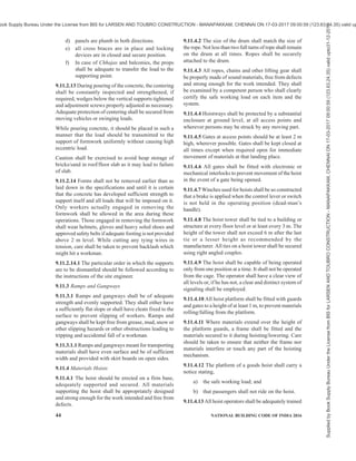
![42 NATIONAL BUILDING CODE OF INDIA 2016
9.10.6 Guarding of Floor Openings and Floor Holes
9.10.6.1 Every temporary floor opening shall have
railings, or shall be constantly attended by someone.
Every floor hole into which persons can accidentally
fall shall be guarded by either,
a) a railing with toe board on all exposed sides;
or
b) a floor hole cover of adequate strength and it
should be hinged in place. When the cover is
not in place, the floor hole shall be constantly
attended by someone or shall be protected by
a removable railing.
9.10.6.2 Every stairway floor opening shall be guarded
by a railing on all exposed sides, except at entrance to
stairway. Every ladder way floor opening or platform
shall be guarded by a guard railing with toe board on
all exposed sides (except at entrance to opening), with
the passage through the railing either provided with a
swinging gate or so offset that a person cannot walk
directly into the opening.
9.10.6.3 Guarding of open-side floors and platform
Every open-sided floor or platform 1 200 mm or more
above adjacent floor or ground level shall be guarded
by a railing (or the equivalent) on all open sides, except
where there is entrance to ramp, stair-way, or fixed
ladder. The railing shall be provided with a toe board
beneath the open sides wherever,
a) persons may pass;
b) there is moving machinery; or
c) there is equipment with which falling materials
could create a hazard.
For detailed information, reference may be made to
good practice [7(32)].
9.11 Additional Safety Requirements for Erection
of Concrete Framed Structures (High-Rise
Buildings)
9.11.1 Handling of Plant
9.11.1.1 Mixers
All gears, chains and rollers of mixers shall be properly
guarded. If the mixer has a charging skip the operator
shall ensure that the workers are out of danger before
the skip is lowered. Railings shall be provided on the
ground to prevent anyone walking under the skip while
it is being lowered.
All cables, clamps, hooks, wire ropes, gears and
clutches, etc, of the mixer, shall be checked and cleaned,
oiled and greased, and serviced once a week. A trial
run of the mixer shall be made and defects shall be
removed before operating a mixer.
When workers are cleaning the inside of the drums,
operating power of the mixer shall be locked in the off
position and all fuses shall be removed and a suitable
notice hung at the place.
9.11.1.2 Cranes
Crane rails where used shall be installed on firm ground
and shall be properly secured. In case of tower cranes,
it shall be ensured that the level difference between the
two rails remains within the limits prescribed by the
manufacturer to safeguard against toppling of the crane.
Requirements for tower cranes as given in 7.3 shall
also be complied with.
Electrical wiring which can possibly touch the crane
or any member being lifted shall be removed, or made
dead by removing the controlling fuses and in their
absence controlling switches.
All practical steps shall be taken to prevent the cranes
being operated in dangerous proximity to a live
overhead power line. In particular, no member of the
crane shall be permitted to approach within the
minimum safety distances as laid down in 8.2.23 (a).
If it becomes necessary to operate the cranes with
clearances less than those specified above, it shall be
ensured that the overhead power lines shall invariably
be shut off during the period of operation of cranes.
Location of any underground power cables in the area
of operation shall also be ascertained and necessary
safety precautions shall be taken.
Cranes shall not be used at a speed which causes the
boom to swing.
A crane shall be thoroughly examined at least once in a
period of 6 months by a competent person who shall
record a certificate of the check.
The operator of the crane shall follow the safe reach of
the crane as shown by the manufacturer.
No person shall be lifted or transported by the crane
on its hook or boom.
Toe boards and limit stops should be provided for wheel
barrows on the loading/unloading platforms. Material
should be loaded securely with no projections.
Concrete buckets handled by crane or overhead
cableway shall be suspended from deep throated hooks,
preferably equipped with swivel and safety latch. In
the concrete buckets, both bottom drop type and side
drop type, closing and locking of the exit door of the
bucket shall always be checked by the man-in-charge
of loading concrete in the bucket to avoid accidental
opening of the exit door and consequent falling of
concrete.
Interlocking or other safety devices should be installed
Supplied
by
Book
Supply
Bureau
Under
the
License
from
BIS
for
LARSEN
AND
TOUBRO
CONSTRUCTION
-
MANAPAKKAM,
CHENNAI
ON
17-03-2017
09:00:59
(123.63.24.35)
valid
upto31-12-2017
ook Supply Bureau Under the License from BIS for LARSEN AND TOUBRO CONSTRUCTION - MANAPAKKAM, CHENNAI ON 17-03-2017 09:00:59 (123.63.24.35) valid up](https://image.slidesharecdn.com/india-national-building-code-nbc-2016-vol-2-220512114536-12622fb6/85/india-national-building-code-nbc-2016-vol-2-pdf-52-320.jpg)
![PART 7 CONSTURCTION MANAGEMENT, PRACTICES AND SAFETY 43
at all stopping points of the hoists. The hoists shaft
way should be fenced properly.
When the bucket or other members being lifted are out
of sight of the crane operator, a signalman shall be
posted in clear view of the receiving area and the crane
operator.
A standard code of hand signals shall be adopted in
controlling the movements of the crane, and both the
driver and the signaller shall be thoroughly familiar
with the signals.
The driver of the crane shall respond to signals only
from the appointed signaler but shall obey stop signal
at any time no matter who gives it.
If a travelling gantry crane is operating over casting
beds, a warning signal which sounds automatically
during travel should be provided to avoid accidents to
workers crossing or standing in the path of the moving
loads.
9.11.1.3 Trucks
When trucks are being used on the site, traffic problems
shall be taken care of. A reasonably smooth traffic
surface shall be provided. If practicable, a loop road
shall be provided to permit continuous operation of
vehicles and to eliminate their backing. If a continuous
loop is not possible, a turnout shall be provided.
Backing operations shall be controlled by a signalman
positioned so as to have a clear view of the area behind
the truck and to be clearly visible to the truck driver.
Movement of workers and plant shall be routed to avoid
crossing, as much as possible, the truck lanes.
9.11.1.4 Concrete pumps (Air compressor operated)
Safety requirements in accordance with good practice
[7(33)] shall be followed.
9.11.2 Formwork
9.11.2.1 Formwork shall be designed after taking into
consideration spans, setting temperature of concrete,
dead load and working load to be supported and safety
factor for the materials used for formwork {see also
with good practice [7(26)]}.
9.11.2.2 All timber formwork shall be carefully
inspected before use and members having cracks and
excessive knots shall be discarded.
9.11.2.3 As timber centering usually takes an initial set
when vertical load is applied, the design of this
centering shall make allowance for this factor.
9.11.2.4 The vertical supports shall be adequately
braced or otherwise secured in position that these do
not fall when the load gets released or the supports are
accidently hit.
9.11.2.5 Tubular steel centering shall be used in
accordance with the manufacturer’s instructions. When
tubular steel and timber centering is to be used in
combination necessary precautions shall be taken to
avoid any unequal settlement under load.
9.11.2.6 A thorough inspection of tubular steel centering
is necessary before its erection and members showing
evidence of excessive resting, kinks, dents or damaged
welds shall be discarded. Buckled or broken members
shall be replaced. Care shall also be taken that locking
devices are in good working order and that coupling
pins are effectively aligned to frames.
9.11.2.7 After assembling the basic unit, adjustment
screws shall be set to their approximate final adjustment
and the unit shall be level and plumb so that when
additional frames are installed the tower shall be in
level and plumb. The centering frames shall be tied
together with sufficient braces to make a rigid and solid
unit. It shall be ensured that struts and diagonals braces
are in proper position and are secured so that frames
develop full load carrying capacity. As erection
progresses, all connecting devices shall be in place and
shall be fastened for full stability of joints and units.
9.11.2.8 In case of timber posts, vertical joints shall be
properly designed. The connections shall normally be
with bolts and nuts. Use of rusted or spoiled threaded
bolts and nuts shall be avoided.
9.11.2.9 Unless the timber centering is supported by a
manufacturer’s certificate about the loads it can stand,
centering shall be designed by a competent engineer.
9.11.2.10 Centering layout shall be made by a qualified
engineer and shall be strictly followed. The bearing
capacity of the soil shall be kept in view for every
centering job. The effect of weather conditions as dry
clay may become very plastic after a rainfall and show
marked decrease in its bearing capacity.
9.11.2.11 Sills under the supports shall be set on firm
soil or other suitable material in a pattern which assures
adequate stability for all props. Care shall be taken not
to disturb the soil under the supports. Adequate drainage
shall be provided to drain away water coming due to
rains, washing of forms or during the curing of the
concrete to avoid softening of the supporting soil strata.
9.11.2.12 All centering shall be finally, inspected to
ensure that,
a) footings or sills under every post of the
centering are sound.
b) all lower adjustment screws or wedges are
sung against the legs of the panels.
c) all upper adjustment screws or heads of jacks
are in full contact with the formwork.
Supplied
by
Book
Supply
Bureau
Under
the
License
from
BIS
for
LARSEN
AND
TOUBRO
CONSTRUCTION
-
MANAPAKKAM,
CHENNAI
ON
17-03-2017
09:00:59
(123.63.24.35)
valid
upto31-12-2017
ook Supply Bureau Under the License from BIS for LARSEN AND TOUBRO CONSTRUCTION - MANAPAKKAM, CHENNAI ON 17-03-2017 09:00:59 (123.63.24.35) valid up](https://image.slidesharecdn.com/india-national-building-code-nbc-2016-vol-2-220512114536-12622fb6/85/india-national-building-code-nbc-2016-vol-2-pdf-53-320.jpg)
![46 NATIONAL BUILDING CODE OF INDIA 2016
protection shall be provided.
9.12 Additional Safety Requirements for Erection
of Structural Steel Work
9.12.1 Safety Organization
The agency responsible for erecting the steel work
should analyze the proposed erection scheme for safety;
the erection scheme should cover safety aspects right
from the planning stage up to the actual execution of
the work.
9.12.2 Safety of Workpersons
9.12.2.1 General
While engaging persons for the job the supervisor
should check up and make sure that they are skilled in
the particular job they have to perform.
The helmets shall be worn properly and at all times
during the work and shall conform to the accepted
standard [7(28)].
The safety goggles shall be used while performing
duties which are hazardous to eye like drilling, cutting
and welding. The goggles used shall conform to the
accepted standard [7(34)] and should suit individual
workers.
The welders and gas cutters shall be equipped with
proper protective equipment like gloves, safety boots,
aprons and hand shields [see accepted standard 7(35)].
The filter glass of the hand shield shall conform to the
accepted standard [7(34)] and should be suitable to the
eyes of the particular worker.
When the work is in progress, the area shall be cordoned
off by barricades to prevent persons from hitting against
structural components, or falling into excavated
trenches or getting injured by falling objects.
Warning signs shall be displayed where necessary to
indicate hazards, for example (a) ‘440 V’, (b) ‘DO NOT
SMOKE’, (c) ‘MEN WORKING AHEAD’, etc. Hand
lamps shall be of low voltage preferably 24 V to prevent
electrical hazards.
All electrically operated hand tools shall be provided
with double earthing.
9.12.2.2 Anchors for guys or ties shall be checked for
proper placement. The weight of concrete in which the
anchors are embedded shall be checked for uplift and
sliding. Split-end eye anchors shall only be used in
good, solid rock. The first load lifted by a guy derrick
shall be kept at a small height for about 10 min and the
anchors immediately inspected for any signs or
indications of failure.
9.12.2.3 When a number of trusses or deep girders are
loaded in one car or on one truck, all but one being
lifted shall be tied back unless they have been tied or
braced to prevent their falling over and endangering
men unloading.
9.12.2.4 The erection gang shall have adequate supply
of bolts, washers, rivets, pins, etc, of the correct size.
Enough number of bolts shall be used in connecting
each piece using a minimum of two bolts in a pattern
to ensure that the joint will not fail due to dead load
and erection loads. All splice connections in columns,
crane girders, etc, shall be completely bolted or riveted
or welded as specified in the drawing before erection.
9.12.2.5 Girders and other heavy complicated structural
members may require special erection devices like
cleats and hooks, which can be shop assembled and
bolted or riveted or welded to the piece and may be
left permanently in the place after the work.
9.12.2.6 If a piece is laterally unstable when picked at
its centre, use of a balance beam is advisable, unless a
pair of bridles slings can be placed far enough apart,
for them to act as safe lifting points. The top flange of
a truss, girder or long beam may be temporarily
reinforced with a structural member laid flat on top of
the member and secured temporarily.
9.12.2.7 On deep girders, and even on some trusses, a
safety ‘bar’ running their full length will aid the riggers,
fitters and others employed on the bottom flange or
bottom chord to work with greater safety. This can be
a single 16 mm diameter wire rope through vertical
stiffeners of such members about 1 m above the bottom
flange and clamped at the ends with wire rope clamps.
If the holes cannot be provided, short eye bolts can be
welded to the webs of the girder at intervals to be
removed and the surface chipped or ground to leave it
smooth after all work on the piece has been completed.
9.12.2.8 Safety belts shall always be available at work
spot to be used, whenever necessary. The rope shall be
chemically treated to resist dew and rotting. These shall
not be tied on sharp edges of steel structures. They shall
be tied generally not more than 2 m to 3 m away from
the belt.
9.12.2.9 On a guy derrick or climbing crane job, the
tool boxes used by the erection staff shall be moved to
the new working floor each time the rig is changed. On
a mobile crane job, the boxes shall be moved as soon
as the crane starts operating in a new area not too far
away for the men to reach the boxes conveniently. While
working a tall and heavy guy derrick, it is advisable to
control tension in guys by hand winches to avoid jerks,
which may cause an accident.
9.12.2.10 The proper size, number and spacing of wire
rope clamps shall be used, depending on the diameter
of the wire rope. They shall be properly fixed in
Supplied
by
Book
Supply
Bureau
Under
the
License
from
BIS
for
LARSEN
AND
TOUBRO
CONSTRUCTION
-
MANAPAKKAM,
CHENNAI
ON
17-03-2017
09:00:59
(123.63.24.35)
valid
upto31-12-2017
ook Supply Bureau Under the License from BIS for LARSEN AND TOUBRO CONSTRUCTION - MANAPAKKAM, CHENNAI ON 17-03-2017 09:00:59 (123.63.24.35) valid up](https://image.slidesharecdn.com/india-national-building-code-nbc-2016-vol-2-220512114536-12622fb6/85/india-national-building-code-nbc-2016-vol-2-pdf-56-320.jpg)
![PART 7 CONSTURCTION MANAGEMENT, PRACTICES AND SAFETY 47
accordance with the procedure given in the accepted
standard [7(36)]. They shall be checked as soon as the
rope has been stretched, as the rope, especially if new,
tends to stretch under the applied load, which in turn
may cause it to shrink slightly in diameter. The clamps
shall then be promptly tightened to take care of this
new condition. In addition, the clamps shall be
inspected frequently to be sure that they have not
slipped and are tight enough.
9.12.2.11 When the men can work safely from the steel
structure itself, this is preferable to hanging platforms
or scaffolds, as it eliminates additional operations,
which in turn, reduces the hazard of an accident. To
aid men working on floats or scaffolds, as well as men
in erection gangs, or other gangs using small material,
such as bolts and drift pins, adequate bolt baskets or
similar containers with handles of sufficient strength
and attachment to carry the loaded containers, shall be
provided. The men should be trained to use such
containers, and to keep small tools gathered up and
put away in tool boxes when not in use. Material shall
not be dumped overboard when a scaffold is to be
moved. Rivet heaters shall have safe containers or
buckets for hot rivets left over at the end of the day.
9.12.2.12 During the erection of tall buildings, it is
desirable to use nylon nets of sufficient width at a height
of 3 m to 4 m from ground to provide safety to people.
The safety net should be made from man-made or
machine-made fibre ropes which are UV stabilized and
conforming to the accepted standard [7(37)].
9.12.2.13 Safety against fire
A fire protection procedure is to be set up if there is to
be any flame cutting, burning, heating, riveting or any
operation that could start a fire. For precautions to be
observed during welding and cutting operations,
reference may be made to good practice [7(38)]. The
workers should be instructed not to throw objects like
hot rivets, cigarette stubs, etc, around. Sufficient fire
extinguishers shall be placed at strategic points.
Extinguishers shall always be placed in cranes, hoists,
compressors and similar places. Where electrical
equipmentareinvolved,CO2 ordrypowderextinguishers
shall be provided {see also good practice [7(24)]}.
9.12.2.14 Riding on a load, tackle or runner shall be
prohibited.
9.12.2.15 The load shall never be allowed to rest on
wire ropes. Ropes in operation should not be touched.
Wire rope with broken strand shall not be used for
erection work. Wire ropes/manila ropes conforming to
acceptable standards [7(39)] shall be used for guying.
9.12.2.16 Lifting appliances
Precautions as laid down in 9.11.1.2 shall be followed.
9.12.2.17 Slinging
Chains shall not be joined by bolting or wiring links
together. They shall not be shortened by tying knots. A
chain in which the links are locked, stretched or do not
move freely shall not be used. The chain shall be free
of kinks and twists. Proper eye splices shall be used to
attach the chain hooks.
Pulley blocks of the proper size shall be used to allow
the rope free play in the sheave grooves and to protect
the wire rope from sharp bends under load. Idle sling
should not be carried on the crane hook alongwith a
loaded sling. When idle slings are carried they shall be
hooked.
While using multilegged slings, each sling or leg shall
be loaded evenly and the slings shall be of sufficient
length to avoid a wide angle between the legs.
9.12.2.18 Riveting operations
9.12.2.18.1 Handling rivets
Care shall be taken while handling rivets so that they
do not fall, strike or cause injury to men and material
below. Rivet catchers shall have false wooden bottoms
to prevent rivets from rebounding.
9.12.2.18.2 Riveting dollies
Canvas, leather or rope slings shall be used for riveting
dollies. Chain shall not be used for the purpose.
9.12.2.18.3 Riveting hammers
Snaps and plungers of pneumatic riveting hammers
shall be secured to prevent the snap from dropping out
of place. The nozzle of the hammer shall be inspected
periodically and the wire attachment renewed when
born.
9.12.2.18.4 Fire protection
The rivet heating equipment should be as near as
possible to the place of work. A pail of water shall
always be kept ready for quenching the fire during
riveting operations and to prevent fires when working
near inflammable materials.
9.12.2.19 Welding and gas cutting
9.12.2.19.1 For safety and health requirements in
electric gas welding and cutting operations, reference
may be made to good practice [7(40)]. The
recommendations given in 9.12.2.19.2 to 9.12.2.19.4
are also applicable.
9.12.2.19.2 All gas cylinders shall be used and stored
in the upright position only and shall be conveyed in
trolleys. While handling by cranes they shall be carried
in cages. The cylinders shall be marked ‘full’ or ‘empty’
as the case may be. Gas cylinders shall be stored away
Supplied
by
Book
Supply
Bureau
Under
the
License
from
BIS
for
LARSEN
AND
TOUBRO
CONSTRUCTION
-
MANAPAKKAM,
CHENNAI
ON
17-03-2017
09:00:59
(123.63.24.35)
valid
upto31-12-2017
ook Supply Bureau Under the License from BIS for LARSEN AND TOUBRO CONSTRUCTION - MANAPAKKAM, CHENNAI ON 17-03-2017 09:00:59 (123.63.24.35) valid up](https://image.slidesharecdn.com/india-national-building-code-nbc-2016-vol-2-220512114536-12622fb6/85/india-national-building-code-nbc-2016-vol-2-pdf-57-320.jpg)
![48 NATIONAL BUILDING CODE OF INDIA 2016
from open flames and other sources of heat. Oxygen
cylinders shall not be stored near combustible gas, oil,
grease and similar combustible materials. When the
cylinders are in use, cylinder valve key or wrench shall
be placed in position. Before a cylinder is moved,
cylinder valve shall be closed. All cylinder valves shall
be closed when the torches are being replaced or
welding is stopped for some reason. The cylinder valve
and connections shall not be lubricated.
9.12.2.19.3 Gas cutting and welding torches shall be
lighted by means of special lighters and not with
matches. The cables from welding equipment should
be placed in such a way that they are not run over by
traffic. Double earthing shall be provided. Before
undertaking welding operations near combustible
materials, suitable blanketing shall be provided and fire
extinguishers kept nearby. Welding shall not be
undertaken in areas where inflammable liquids and
gases are stored.
9.12.2.19.4 Gas lines and compressed air lines shall
be identified by suitable colour codes for easy
identification, to avoid confusion and to prevent fire
and explosion hazards.
9.12.3 Safety of Structure
9.12.3.1 General
The structure itself should be safeguarded during its
erection. The first truss of the roof system shall be guyed
on each side before the hoisting rope is detached from
it. After the subsequent trusses and roof purlins are
erected, protective guides shall be firmly established
and the required wind bracings shall be erected to
prevent the whole structure being blown over by a
sudden gale at night. Bracing and guying precautions
shall be taken on every structure until it is complete.
Guying shall be specifically done for trusses and
structural components which after their erection form
an erection device. On structures used for temporary
material storage overloading shall be avoided.
9.12.3.1.1 Erection of columns shall be immediately
followed by vertical bracing between columns before
the roof structure is erected.
9.13 Miscellaneous Items
9.13.1 Staircase Construction
While staircase is under construction, depending on
the type of construction, namely, concrete or brickwork,
etc, suitable precautions shall be taken by way of
support, formworks, etc, to prevent any collapse.
Workers or any other person shall not be allowed to
use such staircases till they are tested and found fit for
usage by the Authority/engineer-in-charge. Till the
permanent handrails are provided, temporary provisions
like ropes, etc, shall be provided on staircases prior to
commencement of use of such staircases.
9.13.2 Lift Wells
Till the installation of the lift is completed, lift wells
shall be protected with check boards or railings together
with notice boards, danger lights, etc, to prevent persons
accidentally falling into the wells. The handrails
provided shall be capable of withstanding pressure
exerted due to normal bumping of an individual against
the same.
9.13.3 Construction Involving the Use of Hot
Bituminous Tar Materials
9.13.3.1 Safety programme
9.13.3.1.1 General
On all major works, an experienced and competent
foreman or supervisor shall be placed in-charge of the
work, and shall be made responsible for the strict
observance of the safety rules. He shall stock the
necessary protective equipment, fire extinguishing
equipment, first-aid kit, etc. He shall also keep a record
of the accidents taking place on any particular job, with
reasons thereof, and shall suggest suitable remedial
measures to the management for prevention thereof.
9.13.3.1.2 Protective covering
Workers engaged on jobs involving handling of hot
bitumen, tar, and bituminous mixtures shall use
protective wears, such as boots and gloves, preferably
of asbestos or otherwise of rubber; goggles and helmet.
No workers shall be permitted to handle such materials
without wearing the needed protective covering.
9.13.3.1.3 Fire fighting arrangements
When heating and handling of hot bituminous materials
is to be done in the open, sufficient stocks of clean dry
sand or loose earth shall be made available at the work
site to cope with any resultant fires. When neither such
materials are available, nor are any suitable type of fire
extinguishers provided at the work site in the open,
and reliance has to be on using water for fighting any
fire, the water supply available should be in abundance
and the water shall be applied to the fire in the form of
spray. When heating of bituminous materials is carried
out in enclosed spaces, sufficient number of properly
maintained dry powder fire extinguisher or foam
extinguisher conforming to accepted standards [7(23)]
shall be kept in readiness on the work site.
9.13.3.2 Sprayer, spreader/paver
9.13.3.2.1 Sprayer
The sprayer shall be provided with a fire resisting
screen. The screen shall have an observation window.
Supplied
by
Book
Supply
Bureau
Under
the
License
from
BIS
for
LARSEN
AND
TOUBRO
CONSTRUCTION
-
MANAPAKKAM,
CHENNAI
ON
17-03-2017
09:00:59
(123.63.24.35)
valid
upto31-12-2017
ook Supply Bureau Under the License from BIS for LARSEN AND TOUBRO CONSTRUCTION - MANAPAKKAM, CHENNAI ON 17-03-2017 09:00:59 (123.63.24.35) valid up](https://image.slidesharecdn.com/india-national-building-code-nbc-2016-vol-2-220512114536-12622fb6/85/india-national-building-code-nbc-2016-vol-2-pdf-58-320.jpg)

![50 NATIONAL BUILDING CODE OF INDIA 2016
9.13.3.5 Bitumen plants
Safety requirements shall be in accordance with good
practice [7(41)].
9.13.4 Timber Structure
Preventive measures against hazards in work places
involving construction of timber structures shall be
taken in accordance with good practice [7(42)].
9.14 Finishes
9.14.1 Painting, Polishing and Other Finishes
Only the quantity of paint, thinner and polish required
for the day’s work should be kept at the work spot.
9.14.1.1 All containers of paint, thinner and polish
which are not in actual use should be closed with tight
fitting lids and kept at a safe place away from the actual
work site.
9.14.1.2 A 5 kg dry powder fire extinguisher
conforming to the accepted standard [7(43)] shall be
kept handy.
9.14.1.3 Metal receptacles with pedal operated metal
lids shall be kept handy at the work site for depositing
used cotton rags/waste. The contents of such receptacles
shall be disposed off before the end of each day’s work
at a safe place, preferably by burning under proper
supervision.
9.14.1.4 All containers of paint shall be removed from
the work site and deposited in the paint store before
the close of day’s work. Used paint brushes shall be
cleaned and deposited in the store along with the
containers.
9.14.1.5 Some paints/polishing and finishing materials
are injurious to the health of workers. Adequate
protective clothing, respiratory equipment, etc, shall
be provided for the use of workers during such
operations where necessary.
9.15 Fragile Fixtures
It shall be ensured that sufficient number of workers
and equipment are provided to carry the fragile fixtures
like sanitary fittings, glass panes, etc, to prevent injury
to workers due to accidental dropping of such fixtures.
9.16 Safety in Special Operations
Safety in compressed air work, drilling, blasting and
welding operations shall be in accordance with good
practices [7(44)].
9.17 Electrical Installations and Lifts
9.17.1 Temporary Electrical Wiring
9.17.1.1 Frayed and/or bare wires shall not be used for
temporary electrical connections during construction.
All temporary wiring shall be installed and supervised
by a competent electrician. Adequate protection shall
be provided for all electrical wiring laid on floor which
may have to be crossed over by construction machinery
or by the workers. All flexible wiring connecting the
electrical appliances shall have adequate mechanical
strength and shall preferably be enclosed in a flexible
metal sheath. Overhead wires/cables shall be so laid
that they leave adequate head room.
9.17.1.2 All electrical circuits, other than those required
for illumination of the site at night, shall be switched
off at the close of day’s work. The main switch board
from which connections are taken for lighting, power
operated machinery, etc, shall be located in an easily
accessible and prominent place. No articles of clothing
nor stores shall be kept at the back of or over the board
or anywhere near it. One 3 kg/4.5 kg CO2 extinguisher
or one 5 kg dry powder extinguisher conforming to the
accepted standard [7(43)] shall be provided near the
switch board.
9.7.1.3 Requirements as given in 12 of Part 8 ‘Building
Services, Section 2 Electrical and Allied Installations’
of the Code shall also be complied with.
9.17.2 Permanent Electrical Installations
Besides the fire safety measures for electrical
installations covered under 9.17.1, safety in electric
installations in buildings and installations of lifts shall
be in accordance with 12 of Part 8 ‘Building Services,
Section 2 Electrical and Allied Installations’ of the
Code, and Part 8 ‘Building Services, Section 5
Installation of Lifts, Escalators and Moving Walks’ of
the Code, respectively.
9.18 General Safety Requirements for Workplace
9.18.1 Sanitation
a) Adequate toilet facilities shall be provided for
the workers within easy access of their place
of work. The total number to be provided shall
be not less than one per 30 employees in any
one shift.
b) Toilet facilities shall be provided from the start
of building operations, and connection to a
sewer shall be made as soon as practicable.
c) Every toilet shall be so constructed that the
occupant is sheltered from view and protected
from the weather and falling objects.
d) Toilet facilities shall be maintained in a
sanitary condition. A sufficient quantity of
disinfectant shall be provided. Natural or
artificial illumination shall be provided.
Supplied
by
Book
Supply
Bureau
Under
the
License
from
BIS
for
LARSEN
AND
TOUBRO
CONSTRUCTION
-
MANAPAKKAM,
CHENNAI
ON
17-03-2017
09:00:59
(123.63.24.35)
valid
upto31-12-2017
ook Supply Bureau Under the License from BIS for LARSEN AND TOUBRO CONSTRUCTION - MANAPAKKAM, CHENNAI ON 17-03-2017 09:00:59 (123.63.24.35) valid up](https://image.slidesharecdn.com/india-national-building-code-nbc-2016-vol-2-220512114536-12622fb6/85/india-national-building-code-nbc-2016-vol-2-pdf-60-320.jpg)
![PART 7 CONSTURCTION MANAGEMENT, PRACTICES AND SAFETY 51
e) An adequate supply of drinking water shall
be provided, and unless connected to a
municipal water supply, samples of the water
shall be tested at frequent intervals by the
Authority.
9.18.2 Fire Protection
9.18.2.1 In addition to the provision of fire extinguishers,
asspecifiedinthispartoftheCode,otherfireextinguishing
equipmentshallalsobeprovidedandconvenientlylocated
within the building under construction or on the building
site, as required by the Authority.
9.18.2.1.1 All fire extinguishers shall be maintained in
a serviceable condition at all times in accordance with
good practice [7(24)] and all necessary guidelines
regarding fire protection at workplaces followed in
accordance with good practice [7(21)].
9.18.2.1.2 It shall be ensured that all workers and
supervisory staff are fully conversant with the correct
operation and use of fire extinguishers provided at the
construction site.
9.18.2.1.3 Telephone number of local fire brigade
should be prominently displayed near each telephone
provided at construction site.
9.18.2.1.4 Watch and ward services should be provided
at construction sites during holidays and nights.
9.18.2.2 Access shall be provided and maintained at
all times to all fire fighting equipment, including fire
hose, extinguishers, sprinkler valves and hydrants.
9.18.2.2.1 Approach roads for fire fighting should be
planned, properly maintained and kept free from
blockage. Width of approach road should be not less
than 5 m to facilitate fire fighting operations.
9.18.2.2.2 Emergency plan and fire order specifying
the individual responsibility in the event of fire should
be formulated and mock drills should be practised
periodically in case of large and important construction
sites to ensure upkeep and efficiency of fire fighting
appliances.
9.18.2.2.3 Periodical inspection should be carried out
to identify any hazard and proper records maintained
and follow up action taken.
9.18.2.2.4 Evacuation facilities and fire exits should
be provided at all locations susceptible to fire hazards.
9.18.2.3 Where the building plans require the
installation of fixed fire fighting equipment, such as
hydrants, stand pipes, sprinklers and underground water
mains or other suitable arrangements for provision of
water shall be installed, completed and made available
for permanent use as soon as possible, but in any case
not later than the stage at which the hydrants, etc, are
required for use as specified in 9.18.2.3.1 to 9.18.2.3.4.
9.18.2.3.1 A stand pipe system (landing valves),
permanent in nature shall be installed and made
available before the building has reached the height of
15 m above the grade, and carried up with each floor.
9.18.2.3.2 The standpipe (landing valve/internal fire
hydrant) and its installation shall conform to the
accepted standards [7(45)].
9.18.2.3.3 The standpipe shall be carried up with each
floor and securely capped at the top. Top hose outlets,
should at all times, be not more than one floor below
the floor under construction.
9.18.2.3.4 A substantial box, preferably of metal, should
be provided and maintained near each hose outlet. The
box should contain adequate lengths of hose to reach
all parts of the floor as well as a short branch fitted
with 12 mm or 20 mm nozzle.
9.18.2.4 Close liaison shall be maintained with the local
Fire Brigade, during construction of all buildings above
15 m in height and special occupancies, like
educational, assembly, institutional, industrial, storage,
hazardous and mixed occupancies with any of the
aforesaid occupancies having area more than 500 m2
on each floor.
9.18.2.5 It is desirable that telephone system or other
means of inter-communication system be provided
during the construction of all buildings over 15 m in
height or buildings having a plinth area in excess
of 1 000 m2
.
9.18.2.6 All work waste, such as scrap timber, wood
shavings, sawdust, paper, packing materials and oily
waste shall be collected and disposed of safely at the
end of each day’s work. Particular care shall be taken
to remove all waste accumulation in or near vertical
shaft openings like stairways, lift-shaft, etc.
9.18.2.7 An independent water storage facility shall be
provided before the commencement of construction
operations for fire-fighting purposes. It shall be
maintained and be available for use at all times.
9.18.2.8 Fire cut-offs
Fire walls and exit stairways required for a building
should be given construction priority. Where fire doors,
with or without automatic closing devices, are stipulated
in the building plans they should be hung as soon as
practicable and before any significant quantity of
combustible material is introduced in the building.
9.18.2.8.1 As the work progresses, the provision of
permanent stairways, stairway enclosures, fire walls and
other features of the completed structure which will
prevent the horizontal and vertical spread of fire should
be ensured.
Supplied
by
Book
Supply
Bureau
Under
the
License
from
BIS
for
LARSEN
AND
TOUBRO
CONSTRUCTION
-
MANAPAKKAM,
CHENNAI
ON
17-03-2017
09:00:59
(123.63.24.35)
valid
upto31-12-2017
ook Supply Bureau Under the License from BIS for LARSEN AND TOUBRO CONSTRUCTION - MANAPAKKAM, CHENNAI ON 17-03-2017 09:00:59 (123.63.24.35) valid up](https://image.slidesharecdn.com/india-national-building-code-nbc-2016-vol-2-220512114536-12622fb6/85/india-national-building-code-nbc-2016-vol-2-pdf-61-320.jpg)
![52 NATIONAL BUILDING CODE OF INDIA 2016
9.18.3 Clothing
9.18.3.1 It shall be ensured that the clothes worn by
the workers be not of such nature as to increase the
chances of their getting involved in accident to
themselves or to others. As a rule, wearing of Chaddars
or loose garments shall be prohibited.
9.18.3.2 Workers engaged in processes which splash
liquid or other materials which will injure the skin shall
have enough protective clothing to cover the body.
9.18.3.3 Individuals engaged in work involving use of
naked flames (such as welding) shall not wear synthetic
fibre or similar clothing which increases the risk of fire
hazards.
9.18.4 Safety Measures Against Fall Prevention
Persons working at heights may use safety belts and
harnesses. Provision of cat-walks, wire mesh, railings
reduces chances of fall-ladder and scaffoldings,
stagings, etc, should be anchored on firm footing and
should be secured and railing should be provided as
far as possible. All accesses should be barricaded to
prevent accidental fall. For details as fall prevention
reference may be made to good practice [7(46)].
9.18.5 Falling Materials Hazard Prevention
Preventive measures against falling materials hazards
in work places shall be taken in accordance with good
practice [7(47)].
9.18.6 Disposal of Debris
Preventive measures against hazards relating to disposal
of debris shall be taken in accordance with [7(48)].
9.19 Construction Machinery
9.19.1 Specification and requirements of construction
machinery used in construction or demolition work shall
conform to accepted standards [7(49)].
9.19.2 For safety requirements for working with
construction machinery, reference may be made to good
practice [7(50)].
9.19.3 Petroleum powered air compressors, hoists,
derricks, pumps, etc, shall be so located that the
exhausts are well away from combustible materials.
Where the exhausts are pipes to outside the building
under construction, a clearance of at least 150 mm shall
be maintained between such piping and combustible
material.
9.19.4 Earthing/grounding of electrically powered
equipment/tools shall be ensured. Also all electric
powered equipment should be switched off from mains,
after completion of day’s job.
10 SAFETY IN DEMOLITION OF BUILDINGS
10.1 The safety requirements for carrying out
demolition/dismantling work shall be as given in 10.2
to 10.15.
10.2 Planning
Before beginning the actual work of demolition a
careful study shall be made of the structure which is to
be pulled down and also of all its surroundings. This
shall, in particular, include study of the manner in which
the various parts of the building to be demolished are
supported and how far the stage by stage demolition
will affect the safety of the adjoining structure. A
definite plan of procedure for the demolition work,
depending upon the manner in which the loads of the
various structural parts are supported, shall be prepared
and approved by the engineer-in-charge and this shall
be followed as closely as possible, in actual execution
of the demolition work. Before the commencement of
each stage of demolition, the foreman shall brief the
workers in detail regarding the safety aspects to be kept
in view.
It should be ensured that the demolition operations do
not, at any stage, and endanger the safety of the
adjoining buildings. Moreover, the nuisance effect of
the demolishing work on the use of the adjacent
buildings should be kept to the minimum.
No structure or part of the structure or any floor or
temporary support or scaffold, side wall or any device
for equipment shall be loaded in excess of the safe
carrying capacity, in its then existing condition.
Electrical installations for demolition sites shall be in
accordance with 12 of Part 8 ‘Building Services,
Section 2 Electrical and Allied Installations’ of the
Code.
10.3 Precautions Prior to Demolition
10.3.1 On every demolition job, danger signs shall be
conspicuously posted all around the structure and all
doors and openings giving access to the structure shall
be kept barricaded or manned except during the actual
passage of workers or equipment. However, provisions
shall be made for at least two independent exits for
escape of workers during any emergency.
10.3.2 During nights, red lights shall be placed on or
about all the barricades.
10.3.3 Where in any work of demolition it is imperative,
because of danger existing, to ensure that no
unauthorized person shall enter the site of demolition
during the outside hours; a watchman should be
employed. In addition to watching the site he shall also
be responsible for maintaining all notices, lights and
barricades.
Supplied
by
Book
Supply
Bureau
Under
the
License
from
BIS
for
LARSEN
AND
TOUBRO
CONSTRUCTION
-
MANAPAKKAM,
CHENNAI
ON
17-03-2017
09:00:59
(123.63.24.35)
valid
upto31-12-2017
ook Supply Bureau Under the License from BIS for LARSEN AND TOUBRO CONSTRUCTION - MANAPAKKAM, CHENNAI ON 17-03-2017 09:00:59 (123.63.24.35) valid up](https://image.slidesharecdn.com/india-national-building-code-nbc-2016-vol-2-220512114536-12622fb6/85/india-national-building-code-nbc-2016-vol-2-pdf-62-320.jpg)
![PART 7 CONSTURCTION MANAGEMENT, PRACTICES AND SAFETY 53
10.3.4 All the necessary safety appliances shall be
issued to the workers and their use explained. It shall
be ensured that the workers are using all the safety
appliances while at work.
10.3.5 The power on all electrical service lines shall
be shut off and all such lines cut or disconnected at or
outside the property line, before the demolition work
is started. Prior to cutting of such lines, the necessary
approval shall be obtained from the electrical
authorities concerned. The only exception will be any
power lines required for demolition work itself.
10.3.6 All gas, water steam and other service lines shall
be shut off and capped or otherwise controlled at or
outside the building line, before demolition work is
started.
10.3.7 All the mains and meters of the building shall
be removed or protected from damage.
10.3.8 If a structure to be demolished has been partially
wrecked by fire, explosion or other catastrophe, the
walls and damaged roofs shall be shored or braced
suitably.
10.3.9 Protection of the Public
10.3.9.1 Safety distances to ensure safety of the public
shall be clearly marked and prominently sign posted.
Every sidewalk or road adjacent to the work shall be
closed or protected. All main roads, which are open to
the public, shall be kept open to the public clear and
unobstructed at all times. Diversions for pedestrians
shall be constructed, where necessary for safety.
10.3.9.2 If the structure to be demolished is more than
two storeyed or 7.5 m high, measured from the side
walk or street which cannot be closed or safely diverted,
and the horizontal distance from the inside of the
sidewalk to the structure is 4.5 m or less, a substantial
sidewalk shed shall be constructed over the entire length
of the sidewalk adjacent to the structure, of sufficient
width with a view to accommodating the pedestrian
traffic without causing congestion. The side walk shed
shall be lighted sufficiently to ensure safety at all times.
For detailed information reference may be made to good
practice [7(51)].
A toe board of at least 1 m high above the roof of the
shed shall be provided on the outside edge and ends of
the sidewalk shed. Such boards may be vertical or
inclined outward at not more than 45°.
Except where the roof of a sidewalk shed solidly abuts
the structure, the face of the sidewalk shed towards the
building shall be completely closed by providing
sheeting/planking to prevent falling material from
penetrating into the shed.
The roof of sidewalk sheds shall be capable of
sustaining a load of 73 N/mm2
. Only in exceptional
cases, say due to lack of other space, the storing of
material on a sidewalk shed may be permitted in which
case the shed shall be designed for a load of 146 N/mm2
.
Roof of sidewalk shed shall be designed taking into
account the impact of the falling debris. By frequent
removal of loads it shall be ensured that the maximum
load, at any time, on the roof of work shed is not more
than 6 000 N/m2
. The height of sidewalk shed shall be
such as to give a minimum clearance of 2.4 m.
Sidewalk shed opening, for loading purposes, shall be
kept closed at all time except during actual loading
operations.
The deck flooring of the sidewalk shed shall consist of
plank of not less than 50 mm in thickness closely laid
and deck made watertight. All members of the shed
shall be adequately braced and connected to resist
displacement of members or distortion of framework.
10.3.9.3 When the horizontal distance from the inside
of the sidewalk to the structure is more than 4.5 m and
less than 7.5 m, a sidewalk shed or fence or a substantial
railing shall be constructed on the inside of the sidewalk
or roadway along the entire length of the demolition
side of the property with movable bars as may be
necessary for the proper execution of the work.
NOTE — For guidance on management of pedestrians/cyclists/
vehicles near road construction sites, reference may be made
to IRC SP 55 : 2014 ‘Guidelines on traffic management in work
zones’.
10.4 Precautions During Demolition
10.4.1 Prior to commencement of work, all material of
fragile nature like glass shall be removed.
10.4.2 All openings shall be boarded up.
10.4.3 Dust shall be controlled by suitable means to
prevent harm to workers.
10.4.4 Stacking of materials or debris shall be within
safe limits of the structural member. Additional
supports, where necessary, shall be given.
10.4.5 Adequate natural or artificial lighting and
ventilation shall be provided for the workers.
10.5 Sequence of Demolition Operations
10.5.1 The demolition work shall be proceeded with in
such a way that,
a) it causes the least damage and nuisance to the
adjoining building and the members of the
public; and
b) it satisfies all safety requirements to avoid any
accidents.
10.5.2 All existing fixtures required during demolition
Supplied
by
Book
Supply
Bureau
Under
the
License
from
BIS
for
LARSEN
AND
TOUBRO
CONSTRUCTION
-
MANAPAKKAM,
CHENNAI
ON
17-03-2017
09:00:59
(123.63.24.35)
valid
upto31-12-2017
ook Supply Bureau Under the License from BIS for LARSEN AND TOUBRO CONSTRUCTION - MANAPAKKAM, CHENNAI ON 17-03-2017 09:00:59 (123.63.24.35) valid up](https://image.slidesharecdn.com/india-national-building-code-nbc-2016-vol-2-220512114536-12622fb6/85/india-national-building-code-nbc-2016-vol-2-pdf-63-320.jpg)
![54 NATIONAL BUILDING CODE OF INDIA 2016
operations shall be well protected with substantial
covering to the entire satisfaction of the rules and
regulations of the undertakings or they shall be
temporarily relocated.
10.5.3 Before demolition work is started, glazed sash,
glazed doors and windows, etc, shall be removed. All
fragile and loose fixtures shall be removed. The lath
and all loose plaster shall be stripped off throughout
the entire building. This is advantageous because it
reduces glass breakage and also eliminates a large
amount of dust producing material before more
substantial parts of the buildings are removed.
10.5.4 All well openings which extend down to floor
level shall be barricaded to a height of not less than
one metre above the floor level. This provision shall
not apply to the ground level floor.
10.5.5 All floor openings and shafts not used for
material chutes shall be floored over and be enclosed
with guard rails and toe boards.
10.5.6 The demolition shall always proceed
systematically storey by storey in descending order. All
work in the upper floor shall be completed and
approved by the engineer-in-charge prior to disturbance
to any supporting member on the lower floor.
Demolition of the structure in sections may be permitted
in exceptional cases, if proper precautions are ensured
to prevent injuries to persons and damage to property.
10.6 Walls
10.6.1 While walls of sections of masonry are being
demolished, it shall be ensured that they are not allowed
to fall as single mass upon the floors of the building
that are being demolished so as to exceed the safe
carrying capacity of the floors. Overloading of floors
shall be prevented by removing the accumulating debris
through chutes or by other means immediately. The
floor shall be inspected by the engineer-in-charge before
undertaking demolition work and if the same is found
to be incapable to carry the load of the debris, necessary
additional precautions shall be taken so as to prevent
any possible unexpected collapse of the floor.
10.6.2 Walls shall be removed part by part. Stages shall
be provided for the men to work on if the walls are less
than one and a half brick thick and dangerous to work
by standing over them.
10.6.3 Adequate lateral bracing shall be provided for
walls which are unsound. For detailed information
reference may be made to good practice [7(51)].
10.7 Flooring
10.7.1 Prior to removal of masonry or concrete floor
adequate support centering shall be provided.
10.7.2 When floors are being removed, no worker or
person shall be allowed to work in the area, directly
underneath and such area shall be barricaded to prevent
access to it.
10.7.3 Planks of sufficient strength shall be provided
to give workers firm support to guard against any
unexpected floor collapse.
10.8 Demolition of Steel Structures
10.8.1 When a derrick is used, care shall be taken to
see that the floor on which it is supported is amply
strong for the loading so imposed. If necessary heavy
planking shall be used to distribute the load to floor
beam and girders.
10.8.2 Overloading of equipment shall not be allowed.
10.8.3 Tag lines shall be used on all materials being
lowered or hoisted up and a standard signal system shall
be used and the workers instructed on the signals.
10.8.4 No person shall be permitted to ride the load
line.
10.8.5 No beams shall be cut until precautions have
been taken to prevent it from swinging freely and
possibly striking any worker or equipment or to any
part of the structure being demolished.
10.8.6 All structural steel members shall be lowered
from the building and shall not be allowed to drop.
10.9 Catch Platform
10.9.1 In demolition of exterior walls of multistorey
structures, catch platform of sufficient strength to
prevent injuries to workers below and public shall be
provided, when the external walls are more than 20 m
in height.
10.9.2 Such catch platform shall be constructed and
maintained not more than 3 storeys below the storey
from which exterior wall is being demolished. When
demolition has progressed to within 3 storeys of ground
level, catch platform will not be considered necessary.
10.9.3 Catch platform shall be capable of sustaining a
live load of not less than 6 100 N/m2
.
10.9.4 Materials shall not be dumped on the catch
platform nor shall they be used for storage of materials.
10.10 Stairs, Passageways and Ladders
10.10.1 Stairs with railings, passageways and ladders
shall be left in place as long as possible and maintained
in a safe condition.
10.10.2 All ladders shall be secured against, slipping
out at the bottom and against movement in any direction
at the top.
Supplied
by
Book
Supply
Bureau
Under
the
License
from
BIS
for
LARSEN
AND
TOUBRO
CONSTRUCTION
-
MANAPAKKAM,
CHENNAI
ON
17-03-2017
09:00:59
(123.63.24.35)
valid
upto31-12-2017
ook Supply Bureau Under the License from BIS for LARSEN AND TOUBRO CONSTRUCTION - MANAPAKKAM, CHENNAI ON 17-03-2017 09:00:59 (123.63.24.35) valid up](https://image.slidesharecdn.com/india-national-building-code-nbc-2016-vol-2-220512114536-12622fb6/85/india-national-building-code-nbc-2016-vol-2-pdf-64-320.jpg)
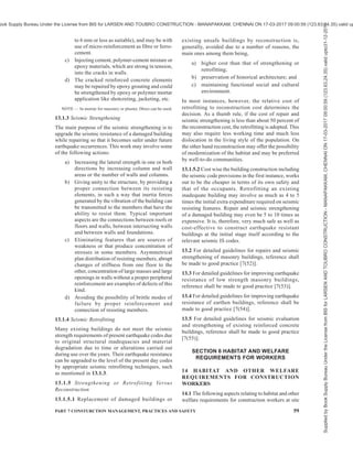
![PART 7 CONSTURCTION MANAGEMENT, PRACTICES AND SAFETY 57
10.13.4.4 Materials which are likely to cause dust
nuisance or undue environmental pollution in any other
way, shall be removed from the site at the earliest and
till then they shall be suitably covered. Such materials
shall be covered during transportation also.
10.13.4.5 Following other requirements should also be
met:
a) Glass and steel should be dumped or buried
separately to prevent injury.
b) Workman should be provided with suitable
protective gears for personal safety during
works, like safety helmets, boots, hand gloves,
goggles, special attire, etc.
c) Work of removal of debris should be carried
out during day. In case of poor visibility
artificial light may be provided.
d) Debris should first be removed from top. Early
removal from bottom or sides of dump may
cause collapse of debris, causing injuries.
10.14 Miscellaneous
10.14.1 No demolition work should be carried out
during night as far as possible, especially when the
structure to be demolished is in an inhabited area. If
such night work has to be done, additional precautions
by way of additional red warning signals, working lights
and watchmen, shall be provided to avoid any injury
to workers and public. Demolition work shall not be
carried out during storm and heavy rain.
10.14.2 Warning devices shall be installed in the area
to warn the workers in case of any danger.
10.14.3 Safety devices like industrial safety helmets
conforming to the accepted standards [7(28)] and
goggles made of celluloid lens, shall be issued to the
workers. Foreman-in-charge of the work areas shall
ensure that all the workers are wearing the safety
devices before commencing any work.
10.14.4 Construction sheds and tool boxes shall be so
located as to protect workers from injuries from the
falling debris.
10.14.5 Where there is a likelihood of injuries to hands
of workers when demolishing RCC, steel structures, etc,
gloves of suitable materials shall be worn by workers.
10.14.6 Sufficient protection by way of both overhead
cover and screens shall be provided to prevent injuries
to the workers and the public.
10.14.7 Safety belts or ropes shall be used by workers
when working at higher levels.
10.14.8 Grading of Plot
When a building has been demolished and no building
operation has been projected or approved, the vacant
plot shall be filled, graded and maintained in conformity
to the established street grades at kerb level. The plot
shall be maintained free from the accumulation of
rubbish and all other unsafe and hazardous conditions
which endangers the life or health of the public; and
provisions shall be made to prevent the accumulation
of water or damage to any foundations on the premises
or the adjoining property.
10.15 First-Aid
10.15.1 A copy of all pertinent regulations and notices
concerning accidents, injury and first-aid shall be
prominently exhibited at the work site.
10.15.2 Depending on the scope and nature of the work,
a person, qualified in first-aid shall be available at work
site to render and direct first-aid to casualties. He shall
maintain a list of individuals qualified to serve in first-
aid work. Enough first-aid kit, including a stretcher and
a cot with accessories shall be provided at site. A
telephone may be provided to first-aid assistant with
telephone numbers of the hospitals prominently
displayed.
Complete reports of all accidents and action taken
thereon shall be forwarded to the competent authorities.
SECTION 5 REPAIRS, RETROFITTING AND
STRENGTHENING OF BUILDINGS
11 MAINTENANCE MANAGEMENT
Maintenance management of building is the art of
preserving over a long period what has been
constructed. Whereas construction stage lasts for a short
period, maintenance continues for comparatively very
large period during the useful life of building.
Inadequate or improper maintenance adversely affects
the environment in which people work, thus affecting
the overall output. In the post construction stage the
day to day maintenance or upkeep of the building shall
certainly delay the decay of the building structure.
Though the building may be designed to be very durable
it needs maintenance to keep it in good condition. The
maintenance management of buildings shall be done
in accordance with Part 12 ‘Asset and Facility
Management’ of the Code.
12 PREVENTION OF CRACKS
12.1 Cracks in buildings are of common occurrence. A
building component develops cracks whenever stress
in the component exceeds its strength. Stress in a
building component could be caused by externally
applied forces, such as dead, imposed, wind or seismic
loads, or foundation settlement or it could be induced
internally due to thermal movements, moisture changes,
chemical action, etc.
Supplied
by
Book
Supply
Bureau
Under
the
License
from
BIS
for
LARSEN
AND
TOUBRO
CONSTRUCTION
-
MANAPAKKAM,
CHENNAI
ON
17-03-2017
09:00:59
(123.63.24.35)
valid
upto31-12-2017
ook Supply Bureau Under the License from BIS for LARSEN AND TOUBRO CONSTRUCTION - MANAPAKKAM, CHENNAI ON 17-03-2017 09:00:59 (123.63.24.35) valid up](https://image.slidesharecdn.com/india-national-building-code-nbc-2016-vol-2-220512114536-12622fb6/85/india-national-building-code-nbc-2016-vol-2-pdf-67-320.jpg)

![PART 7 CONSTURCTION MANAGEMENT, PRACTICES AND SAFETY 59
to 6 mm or less as suitable), and may be with
use of micro-reinforcement as fibre or ferro-
cement.
c) Injecting cement, polymer-cement mixture or
epoxy materials, which are strong in tension,
into the cracks in walls.
d) The cracked reinforced concrete elements
may be repaired by epoxy grouting and could
be strengthened by epoxy or polymer mortar
application like shotcreting, jacketing, etc.
NOTE — In mortar for masonry or plaster, fibres can be used.
13.1.3 Seismic Strengthening
The main purpose of the seismic strengthening is to
upgrade the seismic resistance of a damaged building
while repairing so that it becomes safer under future
earthquake occurrences. This work may involve some
of the following actions:
a) Increasing the lateral strength in one or both
directions by increasing column and wall
areas or the number of walls and columns.
b) Giving unity to the structure, by providing a
proper connection between its resisting
elements, in such a way that inertia forces
generated by the vibration of the building can
be transmitted to the members that have the
ability to resist them. Typical important
aspects are the connections between roofs or
floors and walls, between intersecting walls
and between walls and foundations.
c) Eliminating features that are sources of
weakness or that produce concentration of
stresses in some members. Asymmetrical
plan distribution of resisting members, abrupt
changes of stiffness from one floor to the
other, concentration of large masses and large
openings in walls without a proper peripheral
reinforcement are examples of defects of this
kind.
d) Avoiding the possibility of brittle modes of
failure by proper reinforcement and
connection of resisting members.
13.1.4 Seismic Retrofitting
Many existing buildings do not meet the seismic
strength requirements of present earthquake codes due
to original structural inadequacies and material
degradation due to time or alterations carried out
during use over the years. Their earthquake resistance
can be upgraded to the level of the present day codes
by appropriate seismic retrofitting techniques, such
as mentioned in 13.1.3.
13.1.5 Strengthening or Retrofititng Versus
Reconstruction
13.1.5.1 Replacement of damaged buildings or
existing unsafe buildings by reconstruction is,
generally, avoided due to a number of reasons, the
main ones among them being,
a) higher cost than that of strengthening or
retrofitting;
b) preservation of historical architecture; and
c) maintaining functional social and cultural
environment.
In most instances, however, the relative cost of
retrofitting to reconstruction cost determines the
decision. As a thumb rule, if the cost of repair and
seismic strengthening is less than about 50 percent of
the reconstruction cost, the retrofitting is adopted. This
may also require less working time and much less
dislocation in the living style of the population. On
the other hand reconstruction may offer the possibility
of modernization of the habitat and may be preferred
by well-to-do communities.
13.1.5.2 Cost wise the building construction including
the seismic code provisions in the first instance, works
out to be the cheaper in terms of its own safety and
that of the occupants. Retrofitting an existing
inadequate building may involve as much as 4 to 5
times the initial extra expenditure required on seismic
resisting features. Repair and seismic strengthening
of a damaged building may even be 5 to 10 times as
expensive. It is, therefore, very much safe as well as
cost-effective to construct earthquake resistant
buildings at the initial stage itself according to the
relevant seismic IS codes.
13.2 For detailed guidelines for repairs and seismic
strengthening of masonry buildings, reference shall
be made to good practice [7(52)].
13.3 For detailed guidelines for improving earthquake
resistance of low strength masonry buildings,
reference shall be made to good practice [7(53)].
13.4 For detailed guidelines for improving earthquake
resistance of earthen buildings, reference shall be
made to good practice [7(54)].
13.5 For detailed guidelines for seismic evaluation
and strengthening of existing reinforced concrete
buildings, reference shall be made to good practice
[7(55)].
SECTION 6 HABITAT AND WELFARE
REQUIREMENTS FOR WORKERS
14 HABITAT AND OTHER WELFARE
REQUIREMENTS FOR CONSTRUCTION
WORKERS
14.1 The following aspects relating to habitat and other
welfare requirements for construction workers at site
Supplied
by
Book
Supply
Bureau
Under
the
License
from
BIS
for
LARSEN
AND
TOUBRO
CONSTRUCTION
-
MANAPAKKAM,
CHENNAI
ON
17-03-2017
09:00:59
(123.63.24.35)
valid
upto31-12-2017
ook Supply Bureau Under the License from BIS for LARSEN AND TOUBRO CONSTRUCTION - MANAPAKKAM, CHENNAI ON 17-03-2017 09:00:59 (123.63.24.35) valid up](https://image.slidesharecdn.com/india-national-building-code-nbc-2016-vol-2-220512114536-12622fb6/85/india-national-building-code-nbc-2016-vol-2-pdf-69-320.jpg)

![PART 7 CONSTURCTION MANAGEMENT, PRACTICES AND SAFETY 61
the requirements given in 14.2 to 14.4 shall be
structurally sound and may be constructed at site or
erected as prefabricated single/two storied
accommodation.
14.6 Sanitary Facilities
Following sanitary facilities shall be provided at habitat
for construction workers at site:
a) Every lavatory shall be under cover and so
partitioned off as to secure privacy, and shall
have a proper door and fastenings.
b) Where both male and female building workers
are employed, separate sanitary facilities shall
be provided for female workers. There shall
be displayed outside each block of lavatories
or urinals a notice containing therein ‘For Men
Only’ or ‘For Women Only’, as the case may
be, written in the language understood by the
majority of such workers. Such notice shall
also bear the figure of a man or of a woman,
as the case may be.
c) Every lavatory or urinal shall be conveniently
situated and accessible to building workers at
all times.
d) Every lavatory or urinal and washing facilities
shall be adequately lighted and shall be
maintained in a clean and sanitary condition
at all times.
e) Every lavatory or urinal other than those
connected with a flush sewage system shall
comply with the requirements of the public
health authorities.
f) Water seal lavatories may be provided on the
basis of community toilets or shared toilets as
per the recommendation given in good
practice [7(56)].
g) Water shall be provided by means of a tap or
otherwise so as to be conveniently accessible
in or near every lavatory or urinal.
h) The walls, ceilings and partitions of every
lavatory or urinal shall be white-washed or
colour-washed once in every period of six
months.
j) Waste water from wash areas, bathrooms and
toilets shall be drained in septic tanks/soak
pits and suitably disposed in municipal
sewerage systems. For very large habitat,
sewage treatment plant may be installed. No
waste water shall be discharged to ground or
other sources without proper treatment.
k) Septic tanks/soak pits shall be located at a
minimum distance of 18 m from the wells.
Location of septic tank shall meet the
requirements of good practice [7(57)].
14.7 Drinking Water Requirements
14.7.1 Sufficient quantity of potable water shall be
made available for drinking. Drinking water shall meet
the requirements of the accepted standard [7(58)] and
water quality shall be monitored regularly.
14.7.2 Drinking water outlet shall be so located such
that the distance to travel to nearest outlet shall not be
more than 30 m. Drinking water tanks should be legibly
marked ‘Drinking Water’ in a language understood by
a majority of the workers and shall be located at
least 6 m away from washing place, urinal or lavatory.
14.7.3 Sampling and testing of drinking water for
checking its conformity to meet the requirements
of 14.7.1 should be carried out quarterly through
accredited laboratory.
14.7.4 Storage tanks shall be cleaned as part of regular
maintenance procedure to prevent growth of slime and
collection of sediments.
14.8 First Aid and Medical Facilities
14.8.1 First aid centre shall be established in the habitat
with the required medical facilities. Trained first aiders/
male nurse/doctor shall be employed in the First Aid
Centre depending on the number of workers
accommodated. Sufficient number of first-aid boxes
shall be provided and maintained and the box shall be
distinctly marked ‘First-aid’ and shall be equipped with
specified articles.
14.8.2 An emergency vehicle shall be provided or an
arrangement shall be made with an identified nearby
hospital for providing ambulance for transportation of
serious cases of accident or sickness of workers to the
hospital promptly. Such vehicle should be maintained
in good repair and should be equipped with standard
facilities. The contact details, including phone numbers
of such nearby hospitals shall be readily available to
different managers/supervisors/first-aid facility in-
charge. These phone numbers shall also be suitably
displayed at site.
14.8.3 Details of all the first-aid/medical treatments
shall be logged in the first aid register.
14.8.4 Lighting of 300 lux shall be maintained in the
first aid centre.
14.8.5 Health check-up of all the workers shall be done
at least once in six months by a registered medical
practitioner.
14.8.6 The medical facilities shall meet the provisions
of Building and other Construction Workers
(Regulation of Employment and Conditions of Service)
Act, 1996 and rules framed thereunder.
Supplied
by
Book
Supply
Bureau
Under
the
License
from
BIS
for
LARSEN
AND
TOUBRO
CONSTRUCTION
-
MANAPAKKAM,
CHENNAI
ON
17-03-2017
09:00:59
(123.63.24.35)
valid
upto31-12-2017
ook Supply Bureau Under the License from BIS for LARSEN AND TOUBRO CONSTRUCTION - MANAPAKKAM, CHENNAI ON 17-03-2017 09:00:59 (123.63.24.35) valid up](https://image.slidesharecdn.com/india-national-building-code-nbc-2016-vol-2-220512114536-12622fb6/85/india-national-building-code-nbc-2016-vol-2-pdf-71-320.jpg)


![PART 8 BUILDING SERVICES — SECTION 1 LIGHTING AND NATURAL VENTILATION 11
direct sunshine and glare should be avoided. However,
due allowance should be given to the mutual shading
effects of opposite facades.
3.7 Planting of Trees
Planting of trees in streets and in open spaces should be
done carefully to take advantage of both shades and
sunshine without handicapping the flow of natural winds.
Their advantage in abating glare and in providing cool
and/or warm pockets in developed areas should also be
taken. Some trees shed leaves in winter while retaining
thick foliage in summer. Such trees will be very
advantageous, particularly where southern and western
exposures are concerned, by allowing maximum sun
during winter and effectively blocking it in summer.
3.8 For detailed information regarding orientation of
buildings and recommendations for various climatic
zones of country, reference may be made to good
practice [8-1(1)].
4 LIGHTING
4.1 Principles of Lighting
4.1.1 Aims of Good Lighting
Good lighting is necessary for all buildings and has
three primary aims. The first aim is to promote work
and other activities carried out within the building; the
second aim is to promote the safety of the people using
the building; and the third aim is to create, in
conjunction with the structure and decoration, a
pleasing environment conducive to interest of the
occupants and a sense of their well-being.
4.1.1.1 Realization of these aims involves the following:
a) Careful planning of the brightness and colour
pattern within both the working areas and the
surroundingssothatattentionisdrawnnaturally
to the important areas, detail is seen quickly
and accurately and the room is free from any
sense of gloom or monotony (see 4.1.4);
b) Using directional lighting, where appropriate,
to assist perception of task detail and to give
good modeling;
c) Controlling direct and reflected glare from
light sources to eliminate visual discomfort;
d) In artificial lighting installations, minimizing
flicker from certain types of lamps and paying
attention to the colour rendering properties of
the light;
e) Correlating lighting throughout the building to
prevent excessive differences between adjacent
areas so as to reduce the risk of accidents; and
f) Installing emergency lighting systems, where
necessary.
4.1.2 Planning the Brightness Pattern
The brightness pattern seen within an interior may be
considered as composed of three main parts — the task
itself, immediate background of the task and the general
surroundings of walls, ceiling, floor, equipment and
furnishings.
4.1.2.1 In occupations where the visual demands are
small, the levels of illumination derived from a criterion
of visual performance alone may be too low to satisfy
the other requirements. For such situations, therefore,
illuminance recommendations are based on standards
of welfare, safety and amenity judged appropriate to the
occupations; they are also sufficient to give these tasks
brightness which ensured that the visual performance
exceeds the specified minimum. Unless there are special
circumstances associated with the occupation, it is
recommended that the illuminance of all working areas
within a building should generally be 150 lux.
4.1.2.2 Where work takes place over the whole
utilizable area of room, the illumination over that area
should be reasonably uniform and it is recommended
that the uniformity ratio (minimum illuminance divided
by average illuminance levels) should be not less than
0.7 for the working area.
4.1.2.3 When the task brightness appropriate to an
occupation has been determined, the brightness of the
other parts of the room should be planned to give a
proper emphasis to visual comfort and interest.
A general guide for the brightness relationship within
the normal field of vision should be as follows:
a) For high task brightness Maximum
(above 100 cd/m2
):
1) Between the visual task and 3:1
the adjacent areas like table tops
2) Between the visual task and 10:1
the remote areas of the room
b) For low and medium task brightness (below
100 cd/m2
): The task should be brighter than
both the background and the surroundings; the
lower the task brightness, the less critical is
the relationship.
4.1.2.4 In case of all buildings and facilities open to
and used by the public including all forms of public
housing by the government/civic bodies and private
developers, the requirements for visual contrast as given
in 13 and Annex B of Part 3 ‘Development Control
and Rules and General Building Requirements’ of the
Code shall also be complied with for ensuring visual
comfort for elders and persons with disabilities.
4.1.3 Glare
Excessive contrast or abrupt and large changes in
Supplied
by
Book
Supply
Bureau
Under
the
License
from
BIS
for
LARSEN
AND
TOUBRO
CONSTRUCTION
-
MANAPAKKAM,
CHENNAI
ON
17-03-2017
09:00:59
(123.63.24.35)
valid
upto31-12-2017
ook Supply Bureau Under the License from BIS for LARSEN AND TOUBRO CONSTRUCTION - MANAPAKKAM, CHENNAI ON 17-03-2017 09:00:59 (123.63.24.35) valid up](https://image.slidesharecdn.com/india-national-building-code-nbc-2016-vol-2-220512114536-12622fb6/85/india-national-building-code-nbc-2016-vol-2-pdf-97-320.jpg)
![12 NATIONAL BUILDING CODE OF INDIA 2016
brightness produce the effect of glare. When glare is
present, the efficiency of vision is reduced and small
details or subtle changes in scene cannot be perceived.
It may be,
a) direct glare due to light sources within the field
of vision;
b) reflected glare due to reflections from light
sources or surfaces of excessive brightness;
and
c) veiling glare where the peripheral field is
comparatively very bright.
4.1.3.1 An example of glare sources in daylighting is
the view of the bright sky through a window or skylight,
especially when the surrounding wall or ceiling is
comparatively dark or weakly illuminated. Glare can
be minimised in this case either by shielding the open
sky from direct sight by louvers, external hoods or deep
reveals, curtains or other shading devices or by cross
lighting the surroundings to a comparable level. A
gradual transition of brightness from one portion to the
other within the field of vision always avoids or
minimises the discomfort from glare.
For electric lamps the minimum shielding angles for
lamp luminance shall not be less than the values given
in the table below:
Lamp Luminance
kcd/m2
Minimum Shielding Angle
Degree
1 to 20 10
20 to 50 15
50 to 500 20
³ 500 30
The above mentioned shielding angle should not be
applied to luminaires that do not appear in the field of
view of a worker during usual work and/or do not give
the worker any noticeable disability glare.
Table 4 also gives recommended value of quality class
of direct glare limitation for different tasks. These are
numbers assigned to qualitative limits of direct glare:
high, medium and low quality as 1, 2 and 3, respectively.
For more details reference may be made to good
practice [8–1(2)].
4.1.4 Recommended Values of Illuminance
Table 4 gives recommended values of illuminance
commensurate with the general standards of lighting
described in this Section and related to many
occupations and buildings. These are valid under most
of the conditions whether the illumination is by
daylighting, artificial lighting or a combination of the
two. The great variety of visual tasks makes it
impossible to list them all and those given should be
regarded as representing types of task.
4.1.4.1 The different locations and tasks are grouped
within the following four sections:
a) Industrial buildings and process;
b) Offices, schools and public buildings;
c) Surgeries and hospitals; and
d) Hotels, restaurants, shops and homes.
4.1.4.2 The illumination levels recommended in
Table 4 are those to be maintained at all time on the
task. As circumstances may be significantly different
for different interiors used for the same application or
for different conditions for the same kind of activity, a
range of illuminances is recommended for each type
of interior or activity instead of a single value of
illuminance. Each range consists of three successive
steps of the recommended scale of illuminances. They
represent good practice and should be regarded as
giving order of illumination commonly required rather
than as having some absolute significance. For working
interiors the middle value of each range represents the
recommended service illuminance that would be used
unless one or more of the factors mentioned below
apply.
4.1.4.2.1 The higher value of the range should be used
when,
a) unusually low reflectances or contrasts are
present in the task;
b) errors are costly to rectify;
c) visual work is critical;
d) accuracy or higher productivity is of great
importance; and
e) visual capacity of the worker makes it
necessary.
4.1.4.2.2 The lower value of the range may be used when,
a) reflectances or contrast are unusually high;
b) speed and accuracy is not important; and
c) the task is executed only occasionally.
4.1.4.3 Where a visual task is required to be carried
out throughout an interior, general illumination level
to the recommended value on the working plane is
necessary; where the precise height and location of the
task are not known or cannot be easily specified, the
recommended value is that on horizontal plane 850 mm
above floor level.
NOTE — For an industrial task, working plane for the purpose
of general illumination levels is that on a work place which is
generally 750 mm above the floor level. For certain purposes,
such as viewing the objects of arts, the illumination levels
recommended are for the vertical plane at which the art pieces
are placed.
4.1.4.4 Where the task is localized, the recommended
value is that for the task only; it need not, and sometimes
should not, be the general level of illumination used
Supplied
by
Book
Supply
Bureau
Under
the
License
from
BIS
for
LARSEN
AND
TOUBRO
CONSTRUCTION
-
MANAPAKKAM,
CHENNAI
ON
17-03-2017
09:00:59
(123.63.24.35)
valid
upto31-12-2017
ook Supply Bureau Under the License from BIS for LARSEN AND TOUBRO CONSTRUCTION - MANAPAKKAM, CHENNAI ON 17-03-2017 09:00:59 (123.63.24.35) valid up](https://image.slidesharecdn.com/india-national-building-code-nbc-2016-vol-2-220512114536-12622fb6/85/india-national-building-code-nbc-2016-vol-2-pdf-98-320.jpg)


![26 NATIONAL BUILDING CODE OF INDIA 2016
4.1.7 For detailed information regarding principles of
good lighting, reference may be made to good practice
[8-1(2)].
4.2 Daylighting
The primary source of lighting for daylighting is the
sun. The light received by the earth from the sun consists
of two parts, namely, direct solar illuminance and sky
illuminance. For the purposes of daylighting design,
direct solar illuminance shall not be considered and
only sky illuminance shall be taken as contributing to
illumination of the building interiors during the day.
4.2.1 The relative amount of sky illuminance depends
on the position of the sun defined by its altitude, which
in turn, varies with the latitude of the locality, the day
of the year and the time of the day, as indicated in
Table 5.
4.2.2 The external available horizontal sky illuminance
(diffuse illuminance) values which are exceeded for
about 90 percent of the daytime working hours may be
taken as outdoor design illuminance values for ensuring
adequacy of daylighting design. The outdoor design
sky illuminance varies for different climatic regions of
the country. The recommended design sky illuminance
values are 6 800 lux for cold climate, 8 000 lux for
composite climate, 9 000 lux for warm humid climate,
9 000 lux for temperate climate and 10 500 lux for hot-
dry climate. For integration with the artificial lighting
during daytime working hours an increase of 500 lux
in the recommended sky design illuminance for
daylighting is suggested.
4.2.3 The daylight factor is dependent on the sky
luminance distribution, which varies with atmospheric
conditions. A clear design sky with its non-uniform
distribution of luminance is adopted for the purposes
of design in this Section.
4.2.4 Components of Daylight Factor
Daylight factor is the sum of all the daylight reaching
on an indoor reference point from the following sources:
a) Direct sky visible from the point,
b) External surfaces reflecting light directly to
the point (see Note 1), and
c) Internal surfaces reflecting and inter-reflecting
light to the point.
NOTES
1 External surface reflection may be computed approximately
only for points at the centre of the room, and for detailed analysis
procedures are complicated and these may be ignored for actual
calculations.
2 Each of the three components, when expressed as a ratio or
percent of the simultaneous external illuminance on the
horizontal plane, defines respectively the sky component (SC),
the external reflected component (ERC) and the internal
reflected component (IRC) of the daylight factor.
4.2.4.1 The daylight factors on the horizontal plane only
are usually taken, as the working plane in a room is
generally horizontal; however, the factors in vertical
planes should also be considered when specifying
daylighting values for special cases, such as daylighting
on classrooms, blackboards, pictures and paintings hung
on walls.
4.2.5 Sky Component (SC)
Sky component for a window of any size is computed
by the use of the appropriate table of Annex B.
a) The recommended sky component level
should be ensured generally on the working
plane at the following positions:
1) At a distance of 3 m to 3.75 m from the
window along the central line
perpendicular to the window,
2) At the centre of the room if more
appropriate, and
3) At fixed locations, such as school desks,
blackboards and office tables.
b) The daylight area of the prescribed sky
component should not normally be less than
half the total area of the room.
4.2.5.1 The values obtainable from the tables are for
rectangular, open unglazed windows, with no external
obstructions. The values shall be corrected for the
presence of window bars, glazing and external
obstructions, if any. This assumes the maintenance of
a regular cleaning schedule.
4.2.5.2 Corrections for window bars
The corrections for window bars shall be made by
multiplying the values read from tables in Annex B by
a factor equal to the ratio of the clear opening to the
overall opening.
4.2.5.3 Correction for glazing
Where windows are glazed, the sky components
obtained from Annex A shall be reduced by 10 to
20 percent, provided the panes are of clear and clean
glass. Where glass is of the frosted (ground) type, the
sky components read from Annex A may be reduced
by 15 to 30 percent. In case of tinted or reflective glass
the reduction is about 50 percent. Higher indicated
correction corresponds to larger windows and/or near
reference points. In the case of openings and glazings
which are not vertical, suitable correction shall be taken
into account.
Supplied
by
Book
Supply
Bureau
Under
the
License
from
BIS
for
LARSEN
AND
TOUBRO
CONSTRUCTION
-
MANAPAKKAM,
CHENNAI
ON
17-03-2017
09:00:59
(123.63.24.35)
valid
upto31-12-2017
ook Supply Bureau Under the License from BIS for LARSEN AND TOUBRO CONSTRUCTION - MANAPAKKAM, CHENNAI ON 17-03-2017 09:00:59 (123.63.24.35) valid up](https://image.slidesharecdn.com/india-national-building-code-nbc-2016-vol-2-220512114536-12622fb6/85/india-national-building-code-nbc-2016-vol-2-pdf-112-320.jpg)
![PART 8 BUILDING SERVICES — SECTION 1 LIGHTING AND NATURAL VENTILATION 27
Table 5 Solar Altitudes (to the Nearest Degree) for Indian Latitudes
(Clause 4.2.1)
Period of
Year
22 June 21 March and 23 September 22 December
Hours of
Day
(Sun or
Solar)
Latitude
07 00
17 00
08 00
16 00
09 00
15 00
10 00
14 00
11 00
13 00
12 00
—
07 00
17 00
08 00
16 00
09 00
15 00
10 00
14 00
11 00
13 00
12 00
—
07 00
17 00
08 00
16 00
09 00
15 00
10 00
14 00
11 00
13 00
12 00
—
(1) (2) (3) (4) (5) (6) (7) (8) (9) (10) (11) (12) (13) (14) (15) (16) (17) (18) (19)
10°N 18 31 45 58 70 77 15 30 44 59 72 80 9 23 35 46 53 57
13°N 19 32 46 60 72 80 15 29 44 58 70 77 8 21 33 43 51 54
16°N 20 33 47 61 74 83 14 29 43 56 68 74 7 19 31 41 48 51
19°N 21 34 48 62 75 86 14 28 42 55 66 71 5 18 29 48 45 48
22°N 22 35 49 62 75 89 14 28 41 53 64 68 4 16 27 36 42 45
25°N 23 36 49 63 76 88 13 27 40 52 61 65 3 14 25 34 39 42
28°N 23 36 49 63 76 86 13 26 39 50 59 62 1 13 23 31 37 39
31°N 24 37 50 62 75 82 13 25 37 48 56 56 — 11 21 28 34 36
34°N 25 37 49 62 73 79 12 25 36 46 53 56 — 9 18 26 31 33
4.2.5.4 Correction for external obstructions
There is no separate correction, except that the values
from tables in Annex B shall be read only for the
unobstructed portions of the window.
4.2.6 External Reflected Component (ERC)
The value of the sky component corresponding to the
portion of the window obstructed by the external
obstructions may be found by the use of methods
described in Annex C of good practice [8-1(3)].
These values when multiplied by the correction factors,
corresponding to the mean elevation of obstruction
from the point in question as given in Table 6, can be
taken as the external reflected components for that
point.
Table 6 Correction Factor for ERC
(Clause 4.2.6)
Sl No. Mean Angle of Elevation Correction Factor
(1) (2) (3)
i) 5° 0.086
ii) 15° 0.086
iii) 25° 0.142
iv) 35° 0.192
v) 45° 0.226
vi) 55° 0.274
vii) 65° 0.304
viii) 75° 0.324
ix) 85° 0.334
4.2.6.1 For method of calculating ERC, reference may
be made to accepted standard (see Examples 10 and
11 given in Annex B of good practice [8-1(3)].
4.2.7 Internal Reflected Component (IRC)
The component of daylight factor contributed by
reflection from the inside surfaces varies directly as
the window area and inversely as the total area of
internal surfaces, and depends on the reflection factor
of the floor, wall and roof surfaces inside and of the
ground outside. For rooms white-washed on walls and
ceiling and windows of normal sizes, the IRC will have
sizeable value even at points far away from the window.
External obstructions, when present, will
proportionately reduce IRC. Where accurate values of
IRC are desired, the same may be done in accordance
with the good practice [8-1(3)].
4.2.8 General Principles of Openings to Afford Good
Lighting
4.2.8.1 Generally, while taller openings give greater
penetrations, broader openings give better distribution
of light. It is preferable that some area of the sky at an
altitude of 20° to 25° should light up the working plane.
4.2.8.2 Broader openings may also be equally or more
efficient, provided their sills are raised by 300 mm to
600 mm above the working plane.
NOTE — It is to be noted that while placing window with a
high sill level might help natural lighting, this is likely to reduce
ventilation at work levels. While designing the opening for
ventilation also, a compromise may be made by providing the
sill level about 150 mm below the head level of workers.
4.2.8.3 For a given penetration, a number of small
openings properly positioned along the same, adjacent
or opposite walls will give better distribution of
illumination than a single large opening. The sky
component at any point, due to a number of openings
may be easily determined from the corresponding sky
Supplied
by
Book
Supply
Bureau
Under
the
License
from
BIS
for
LARSEN
AND
TOUBRO
CONSTRUCTION
-
MANAPAKKAM,
CHENNAI
ON
17-03-2017
09:00:59
(123.63.24.35)
valid
upto31-12-2017
ook Supply Bureau Under the License from BIS for LARSEN AND TOUBRO CONSTRUCTION - MANAPAKKAM, CHENNAI ON 17-03-2017 09:00:59 (123.63.24.35) valid up](https://image.slidesharecdn.com/india-national-building-code-nbc-2016-vol-2-220512114536-12622fb6/85/india-national-building-code-nbc-2016-vol-2-pdf-113-320.jpg)
![28 NATIONAL BUILDING CODE OF INDIA 2016
component contour charts appropriately superposed.
The sum of the individual sky component for each
opening at the point gives the overall component due
to all the openings. The same charts may also facilitate
easy drawing of sky component contours due to
multiple openings.
4.2.8.4 Unilateral lighting from side openings will, in
general, be unsatisfactory if the effective width of the
room is more than 2 to 2.5 times the distance from the
floor to the top of the opening. In such cases provision
of light shelves is always advantageous.
4.2.8.5 Openings on two opposite sides will give
greater uniformity of internal daylight illumination,
especially when the room is 7 m or more across. They
also minimise glare by illuminating the wall
surrounding each of the opposing openings. Side
openings on one side and clerestory openings on the
opposite side may be provided where the situation so
requires.
4.2.8.6 Cross-lighting with openings on adjacent walls
tends to increase the diffused lighting within a room.
4.2.8.7 Openings in deep reveals tend to minimise glare
effects.
4.2.8.8 Openings shall be provided with Chajjahs,
louvers, baffles or other shading devices to exclude, as
far as possible, direct sunlight entering the room.
Chajjahs, louvers, etc, reduce the effective height of
the opening for which due allowance shall be made.
Broad and low openings are, in general, much easier
to shade against sunlight entry. Direct sunlight, when
it enters, increases the inside illuminance very
considerably. Glare will result if it falls on walls at low
angles, more so than when it falls on floors, especially
when the floors are dark coloured or less reflective.
4.2.8.9 Light control media, such as translucent glass
panes (opal or matt) surfaced by grinding, etching or
sandblasting, configurated or corrugated glass, certain
types of prismatic glass, tinted glass and glass blasts
are often used. They should be provided, either fixed
or movable outside or inside, especially in the upper
portions of the openings. The lower portions are usually
left clear to afford desirable view. The chief purpose
of such fixtures is to reflect part of the light on to the
roof and thereby increase the diffuse lighting within,
light up the farther areas in the room and thereby
produce a more uniform illumination throughout. They
will also prevent the opening causing serious glare
discomfort to the occupants but will provide some glare
when illuminated by direct sunlight.
4.2.9 Availability of Daylight in Multistoreyed Block
Proper planning and layout of building can add
appreciably to daylighting illumination inside. Certain
dispositions of building masses offer much less mutual
obstruction to daylight than others and have a significant
relevance, especially when intensive site planning is
undertaken. As guidance, the relative availability of
daylight in multi-storeyed blocks (up to 4 storeys) of
different relative orientations may be taken as given in
Table 7.
Table 7 Relative Availability of Daylight on the
Window Plane at Ground Level in a
Four-Storeyed Building Blocks (Clear Design-Sky
as Basis, Daylight Availability Taken as Unity on
an Unobstructed Facade, Values are for the
Centre of the Blocks)
(Clause 4.2.9)
Sl
No.
Distance of
Separation
Between
Blocks
Infinitely
Long
Parallel
Blocks
Parallel
Blocks
Facing Each
Other
(Length =
2 × Height)
Parallel Blocks
facing Gaps
Between
Opposite
Blocks
(Length =
2 × Height)
(1) (2) (3) (4) (5)
i) 0.5 Ht 0.15 0.15 0.25
ii) 1.0 Ht 0.30 0.32 0.38
iii) 1.5 Ht 0.40 0.50 0.55
iv) 2.0 Ht 0.50 0.60 0.68
NOTE — Ht = Height of building.
4.2.10 For specified requirements for daylighting of
special occupancies and areas, reference may be made
to good practice [8-1(4)].
4.3 Artificial Lighting
4.3.1 Artificial lighting may have to be provided,
a) where the recommended illumination levels
have to be obtained by artificial lighting only;
b) to supplement daylighting when the level of
illumination falls below the recommended
value; and
c) where visual task may demand a higher level
of illumination.
4.3.2 Artificial Lighting Design for Interiors
For general lighting purposes, the recommended
practice is to design for a level of illumination on the
working plane on the basis of the recommended levels
for visual tasks given in Table 4 by a method called
‘Lumen method’. In order to make the necessary
detailed calculations concerning the type and quantity
of lighting equipment necessary, advance information
on the surface reflectances of walls, ceilings and floors
is required. Similarly, calculations concerning the
brightness ratio in the interior call for details of the
interior decoration and furnishing. Stepwise guidance
regarding designing the interior lighting systems for a
Supplied
by
Book
Supply
Bureau
Under
the
License
from
BIS
for
LARSEN
AND
TOUBRO
CONSTRUCTION
-
MANAPAKKAM,
CHENNAI
ON
17-03-2017
09:00:59
(123.63.24.35)
valid
upto31-12-2017
ook Supply Bureau Under the License from BIS for LARSEN AND TOUBRO CONSTRUCTION - MANAPAKKAM, CHENNAI ON 17-03-2017 09:00:59 (123.63.24.35) valid up](https://image.slidesharecdn.com/india-national-building-code-nbc-2016-vol-2-220512114536-12622fb6/85/india-national-building-code-nbc-2016-vol-2-pdf-114-320.jpg)
![PART 8 BUILDING SERVICES — SECTION 1 LIGHTING AND NATURAL VENTILATION 29
building using the ‘Lumen method’ is given in 4.3.2.1
to 4.3.2.4.
4.3.2.1 Determination of the illumination level
Recommended value of illumination shall be taken from
Table 4, depending upon the type of work to be carried
out in the location in question and the visual tasks
involved.
4.3.2.2 Selection of the light sources and luminaires
The selection of light sources and luminaires depends
on the choice of lighting system, namely, general
lighting, directional lighting and localized or local
lighting.
4.3.2.3 Determination of the luminous flux
a) The luminous flux (F) reaching the working
plane depends upon the following:
1) Lumen output of the lamps,
2) Type of luminaire,
3) Proportion of the room (room index) (kr),
4) Reflectance of internal surfaces of the
room,
5) Depreciation in the lumen output of the
lamps after burning their rated life, and
6) Depreciation due to dirt collection on
luminaires and room surface.
b) Coefficient of utilization or utilization factor
1) The compilation of tables for the
utilization factor requires a considerable
amount of calculations, especially if these
tables have to cover a wide range of
lighting practices. For every luminaire,
the exact light distribution has to be
measured in the laboratory and their
efficiencies have to be calculated and
measured exactly. These measurements
comprise,
i) the luminous flux radiated by the
luminaires directly to the measuring
surface;
ii) the luminous flux reflected and re-
reflected by the ceiling and the walls
to the measuring surface; and
iii) the inter-reflections between the
ceiling and wall which result in the
measuring surface receiving
additional luminous flux.
All these measurements have to be made
for different reflection factors of the
ceiling and the walls for all necessary
room indices. These tables have also to
indicate the maintenance factor to be
taken for the luminous flux depreciation
throughout the life of an installation due
to ageing of the lamp and owing to the
deposition of dirt on the lamps and
luminaires and room surfaces.
2) The values of the reflection factor of the
ceiling and of the wall are as follows:
White and very light colours : 0.7
Light colours : 0.5
Middle tints : 0.3
Dark colours : 0.1
For the walls, taking into account the
influence of the windows without
curtains, shelves, almirahs and doors with
different colours, etc, should be
estimated.
c) Calculation for determining the luminous flux
[see Table 22 of SP : 41 (ST) — 1987
‘Handbook on functional requirements of
buildings other than industrial buildings’]
av
.
E
A
µ φ
=
or, av.
E A
φ =
µ
, for new condition, and
av.
.
E A
d
φ =
µ
, for working condition
where
φ = total luminous flux of the light sources
installed in the room, in lumens;
Eav = average illumination level required on the
working plane, in lux;
A = area of the working plane, in m2
;
µ = utilization factor in new conditions; and
d = maintenance factor.
In practice, it is easier to calculate straightaway the
number of lamps or luminaires from:
av
lamp
lamp
.
. .
E A
N
d
=
µ φ
av
luminaires
luminaires
.
. .
E A
N
d
=
µ φ
where
φlamp = luminous flux of each lamp, in
lumens
φluminaires = luminous flux of each luminaire, in
lumens
Nlamp = total number of lamps
Nluminaires = total number of luminaires.
Supplied
by
Book
Supply
Bureau
Under
the
License
from
BIS
for
LARSEN
AND
TOUBRO
CONSTRUCTION
-
MANAPAKKAM,
CHENNAI
ON
17-03-2017
09:00:59
(123.63.24.35)
valid
upto31-12-2017
ook Supply Bureau Under the License from BIS for LARSEN AND TOUBRO CONSTRUCTION - MANAPAKKAM, CHENNAI ON 17-03-2017 09:00:59 (123.63.24.35) valid up](https://image.slidesharecdn.com/india-national-building-code-nbc-2016-vol-2-220512114536-12622fb6/85/india-national-building-code-nbc-2016-vol-2-pdf-115-320.jpg)
![30 NATIONAL BUILDING CODE OF INDIA 2016
4.3.2.4 Arrangement of the luminaires
This is done to achieve better uniformly distributed
illumination. The location of the luminaires has an
important effect on the utilization factor.
a) In general, luminaires are spaced ‘x’ metre
apart in either direction, while the distance of
the end luminaire from the wall is ‘0.5x’ metre.
The distance ‘x’ is more or less equal to the
mounting height ‘Hm’ between the luminaire
and the working plane. The utilization factor
tables are calculated for this arrangement of
luminaires [see Table 22 of SP : 41 (ST) –
1987 ‘Handbook on functional requirements
of buildings other than industrial buildings’].
b) For small rooms where the room index (kr) is
less than 1, the distance ‘x’ should always be
less than Hm, since otherwise luminaires
cannot be properly located. In most cases of
such rooms, four or two luminaires are placed
for good general lighting. If, however, in such
rooms only one luminaire is installed in the
middle, higher utilization factors are obtained,
but the uniformity of distribution is poor. For
such cases, references should be made to the
additional tables for kr = 0.6 to 1.25 for
luminaires located centrally.
4.3.3 Artificial Lighting to Supplement Daylighting
4.3.3.1 The need for general supplementary artificial
lighting arises due to diminishing of daylighting beyond
design hours, that is, for solar altitude below 15° or
when dark cloudy conditions occur.
4.3.3.2 The need may also arise for providing artificial
lighting during the day in the innermost parts of the
building which cannot be adequately provided with
daylighting, or when the outside windows are not of
adequate size or when there are unavoidable external
obstructions to the incoming daylighting.
4.3.3.3 The need for supplementary lighting during
the day arises, particularly when the daylighting on the
working plane falls below 100 lux and the surrounding
luminance drops below 19 cd/m2
.
4.3.3.4 The requirement of supplementary artificial
lighting increases with the decrease in daylighting
availability. Therefore, conditions near sunset or sunrise
or equivalent conditions due to clouds or obstructions,
etc, represent the worst conditions when the
supplementary lighting is most needed.
4.3.3.5 The requirement of supplementary artificial
lighting when daylighting availability becomes poor
may be determined from Fig. 3 for an assumed ceiling
height of 3.0 m, depending upon floor area, fenestration
percentage and room surface reflectance. Cool daylight
fluorescent tubes are recommended with semi-direct
luminaires. To ensure a good distribution of
illumination, the mounting height should be between
1.5 m and 2.0 m above the work plane for a separation
of 2.0 m to 3.0 m between the luminaires. Also the
number of lamps should preferably be more in the rear
half of the room than in the vicinity of windows. The
FIG. 3 SUPPLEMENTARY ARTIFICIAL LIGHTING FOR 40 W FLUORESCENT TUBES
Supplied
by
Book
Supply
Bureau
Under
the
License
from
BIS
for
LARSEN
AND
TOUBRO
CONSTRUCTION
-
MANAPAKKAM,
CHENNAI
ON
17-03-2017
09:00:59
(123.63.24.35)
valid
upto31-12-2017
ook Supply Bureau Under the License from BIS for LARSEN AND TOUBRO CONSTRUCTION - MANAPAKKAM, CHENNAI ON 17-03-2017 09:00:59 (123.63.24.35) valid up](https://image.slidesharecdn.com/india-national-building-code-nbc-2016-vol-2-220512114536-12622fb6/85/india-national-building-code-nbc-2016-vol-2-pdf-116-320.jpg)
![PART 8 BUILDING SERVICES — SECTION 1 LIGHTING AND NATURAL VENTILATION 31
following steps may be followed for using Fig. 3 for
determining the number of fluorescent tubes required
for supplementary daylighting.
a) Determine fenestration percentage of the floor
area, that is,
Window area
100
Floor area
×
b) In Fig. 3, refer to the curve corresponding to
the percent fenestration determined above and
the set of reflectances of ceiling, walls and
floor actually provided.
c) For the referred curve of Fig. 3 read, along
the ordinate, the number of 40 W fluorescent
tubes required, corresponding to the given
floor area on the abscissa.
4.3.4 For detailed information on the design aspects
and principles of artificial lighting, reference may be
made to good practice [8-1(2)].
4.3.5 For specific requirements for lighting of special
occupancies and areas, reference may be made to good
practice [8-1(5)].
4.3.6 Electrical installation aspect for artificial lighting
shall be in accordance with Part 8 ‘Building Services,
Section 2 Electrical and Allied Installations’ of the
Code.
4.4 Energy Conservation in Lighting
4.4.1 A substantial portion of the energy consumed on
lighting may be saved by utilization of daylight and
rational design of supplementary artificial lights.
4.4.2 Daytime use of artificial lights may be minimised
by proper design of windows for adequate daylight
indoors. Daylighting design should be according to 4.2.
4.4.3 Fenestration expressed as percentage of floor area
required for satisfactory visual performance of a few
tasks for different separation to height (S/H) ratio of
external obstructions such as opposite buildings may
be obtained from the design nomogram (see Fig. 4).
The obstructions at a distance of three times their height
or more (S/H 3) from a window façade are not
significant and a window facing such an obstruction
may be regarded as a case of unobstructed window.
4.4.3.1 The nomogram consists of horizontal lines
indicating fenestration percentage of floor area and
vertical lines indicating the separation to height ratio
of external obstructions such as opposite buildings. Any
vertical line for separation to height ratio other than
already shown in the nomogram (1.0, 2.0 and 3.0) may
be drawn by designer, if required. For cases where there
is no obstruction, the ordinate corresponding to the
value 3.0 may be used. The value of percentage
fenestration and separation to height ratio are marked
on left hand ordinate and abscissa, respectively. The
illumination levels are marked on the right hand
ordinate. The values given within brackets are the
illumination levels on the work plane at center and rear
of the room. The wattage of fluorescent tubes required
per m2
of the floor area for different illumination levels
is shown on each curve.
4.4.3.2 Following assumptions have been made in the
construction of the nomogram:
a) An average interior finish with ceiling white,
walls off white and floor grey has been
assumed.
b) Ceiling height of 3 m, room depths up to 10 m
and floor area between 30 m2
and 50 m2
have
been assumed. For floor area beyond 50 m2
and less than 30 m2
, the values of percent
fenestration as well as wattage per m2
should
be multiplied by a factor of 0.85 and 1.15,
respectively.
c) It is assumed that windows are of metallic
sashes with louvers of width up to 600 mm or
a Chhajja (balcony projection) at ceiling level
of width up to 2.0 m. For wooden sashes, the
window area should be increased by a factor
of about 1.1.
d) Luminaires emanating more light in the
downward direction than upward direction
(such as reflectors with or without diffusing
plastics) and mounted at a height of 1.5 m to
2.0 m above the work plane have been
considered.
4.4.3.3 Method of use
The following steps shall be followed for the use of
nomogram:
a) Step 1 — Decide the desired illumination level
depending upon the task illumination
requirement in the proposed room and read
the value of watts per m2
on the curve
corresponding to the required illumination
level.
b) Step 2 — Fix the vertical line corresponding
to the given separation to height ratio of
opposite buildings on the abscissa. From the
point of intersection of this vertical line and
the above curve move along horizontal, and
read the value of fenestration percent on the
left hand ordinate.
c) Step 3 — If the floor area is greater than 50 m2
or if it is less than 30 m2
, the value of watt per
m2
as well as fenestration percent may be
easily determined for adequate daylighting
and supplemental artificial lighting for design
Supplied
by
Book
Supply
Bureau
Under
the
License
from
BIS
for
LARSEN
AND
TOUBRO
CONSTRUCTION
-
MANAPAKKAM,
CHENNAI
ON
17-03-2017
09:00:59
(123.63.24.35)
valid
upto31-12-2017
ook Supply Bureau Under the License from BIS for LARSEN AND TOUBRO CONSTRUCTION - MANAPAKKAM, CHENNAI ON 17-03-2017 09:00:59 (123.63.24.35) valid up](https://image.slidesharecdn.com/india-national-building-code-nbc-2016-vol-2-220512114536-12622fb6/85/india-national-building-code-nbc-2016-vol-2-pdf-117-320.jpg)
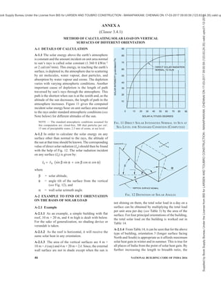
![PART 8 BUILDING SERVICES — SECTION 1 LIGHTING AND NATURAL VENTILATION 45
monitor openings should be closed, but if wind is so
slight that temperature head can overcome it, all
openings may be opened.
5.6.1.5 For method for determining the rate of
ventilation based on probable indoor wind speed with
typical illustrative example for residential building,
reference may be made to A-4 of good practice [9-1(6)].
5.6.2 Mechanical Ventilation
The determination of rate of ventilation in case of
mechanical ventilation shall be done in accordance with
Part 8 ‘Building Services, Section 3 Air Conditioning,
Heating and Mechanical Ventilation’ of the Code.
5.6.3 Combined effect of Different Methods of
Ventilation
When combination of two or more methods of general
ventilation is used, the total rate of ventilation shall be
reckoned as the highest of the following three, and this
rule shall be followed until an exact formula is
established by research:
a) 1.25 times the rate of natural ventilation,
b) Rate of positive ventilation, and
c) Rate of exhaust of air.
5.6.4 Measurement of Air Movement
The rate of air movement of turbulent type at the
working zone shall be measured either with a Kata
thermometer (dry silvered type) or heated thermometer
or properly calibrated thermocouple anemometer.
Whereas anemometer gives the air velocity directly,
the Kata thermometer and heated thermometer give
cooling power of air and the rate of air movement is
found by reference to a suitable nomogram using the
ambient temperature.
5.7 Energy Conservation in Ventilation System
5.7.1 Maximum possible use should be made of wind
induced natural ventilation. This may be accomplished
by following the design guidelines given in 5.7.1.1.
5.7.1.1 Adequate number of circulating fans should be
installedtoserveallinteriorworkingareasduringsummer
months in the hot dry and warm humid regions to provide
necessary air movement at times when ventilation due to
wind action alone does not afford sufficient relief.
5.7.1.1.1 The capacity of a ceiling fan to meet the
requirement of a room with the longer dimension D
metre should be about 55D m3
/min.
5.7.1.1.2 The height of fan blades above the floor
should be (3H + W )/4, where H is the height of the
room, and W is the height of work plane.
5.7.1.1.3 The minimum distance between fan blades
and the ceiling should be about 0.3 m.
5.7.2 Electronic regulators should be used instead of
resistance type regulators for controlling the speed of
fans.
5.7.3 When actual ventilated zone does not cover the
entire room area, then optimum size of ceiling fan
should be chosen based on the actual usable area of
room, rather than the total floor area of the room. Thus
smaller size of fan can be employed and energy saving
could be achieved.
5.7.4 Power consumption by larger fans is obviously
higher, but their power consumption per square metre
of floor area is less and service value higher. Evidently,
improper use of fans irrespective of the rooms’
dimensions is likely to result in higher power
consumption. From the point of view of energy
consumption, the number of fans and the optimum sizes
for rooms of different dimensions are given in Table 13.
Table 13 Optimum Size/Number of Fans for Rooms of Different Sizes
(Clause 5.7.4)
Optimum Size, mm/Number of Fans
for Room Length
Sl
No.
Room
Width
m
4 m 5 m 6 m 7 m 8 m 9 m 10 m 11 m 12 m 14 m 16 m
(1) (2) (3) (4) (5) (6) (7) (8) (9) (10) (11) (12) (13)
i) 3 1 200/1 1 400/1 1 500/1 1 050/2 1 200/2 1 400/2 1 400/2 1 400/2 1 200/3 1 400/3 1 400/3
ii) 4 1 200/1 1 400/1 1 200/2 1 200/2 1 200/2 1 400/2 1 400/2 1 500/2 1 200/3 1 400/3 1 500/3
iii) 5 1 400/1 1 400/1 1 400/2 1 400/2 1 400/2 1 400/2 1 400/2 1 500/2 1 400/3 1 400/3 1 500/3
iv) 6 1 200/2 1 400/2 900/4 1 050/4 1 200/4 1 400/4 1 400/4 1 500/4 1 200/6 1 400/6 1 500/6
v) 7 1 200/2 1 400/2 1 050/4 1 050/4 1 200/4 1 400/4 1 400/4 1 500/4 1 200/6 1 400/6 1 500/6
vi) 8 1 200/2 1 400/2 1 200/4 1 200/4 1 200/4 1 400/4 1 400/4 1 500/4 1 200/6 1 400/6 1 500/6
vii) 9 1 400/2 1 400/2 1 400/4 1 400/4 1 400/4 1 400/4 1 400/4 1 500/4 1 400/6 1 400/6 1 500/6
viii) 10 1 400/2 1 400/2 1 400/4 1 400/4 1 400/4 1 400/4 1 400/4 1 500/4 1 400/6 1 400/6 1 500/6
ix) 11 1 500/2 1 500/2 1 500/4 1 500/4 1 500/4 1 500/4 1 500/4 1 500/4 1 500/6 1 500/6 1 500/6
x) 12 1 200/3 1 400/3 1 200/6 1 200/6 1 200/6 1 400/6 1 400/6 1 500/6 1 200/7 1 400/9 1 400/9
xi) 13 1 400/3 1 400/3 1 200/6 1 200/6 1 200/6 1 400/6 1 400/6 1 500/6 1 400/9 1 400/9 1 500/9
xii) 14 1 400/3 1 400/3 1 400/6 1 400/6 1 400/6 1 400/6 1 400/6 1 500/6 1 400/9 1 400/9 1 500/9
Supplied
by
Book
Supply
Bureau
Under
the
License
from
BIS
for
LARSEN
AND
TOUBRO
CONSTRUCTION
-
MANAPAKKAM,
CHENNAI
ON
17-03-2017
09:00:59
(123.63.24.35)
valid
upto31-12-2017
ook Supply Bureau Under the License from BIS for LARSEN AND TOUBRO CONSTRUCTION - MANAPAKKAM, CHENNAI ON 17-03-2017 09:00:59 (123.63.24.35) valid up](https://image.slidesharecdn.com/india-national-building-code-nbc-2016-vol-2-220512114536-12622fb6/85/india-national-building-code-nbc-2016-vol-2-pdf-131-320.jpg)
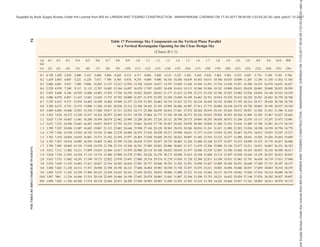


![PART 8 BUILDING SERVICES — SECTION 2 ELECTRICAL AND ALLIED INSTALLATIONS 7
NATIONAL BUILDING CODE OF INDIA
PART 8 BUILDING SERVICES
Section 2 Electrical and Allied Installations
1 SCOPE
This Code (Part 8/Section 2) covers the essential
requirements for electrical installations in buildings to
ensure efficient use of electricity including safety from
fire and shock. This Section also includes general
requirements relating to lightning protection of
buildings and brief provisions on certain allied
installations.
2 TERMINOLOGY AND CONVENTIONAL
SYMBOLS
2.1 For the purpose of this Section, the following
definitions shall apply. For definition of other terms,
reference may be made to accepted standards [8-2(1)].
2.1.1 Accessory — A device, other than current using
equipment, associated with such equipment or with the
wiring of an installation.
2.1.2 Apparatus — Electrical apparatus including all
machines, appliances and fittings in which conductors
are used or of which they form a part.
2.1.3 Appliance — An item of current using equipment
other than a luminaire or an independent motor.
2.1.4 Back-up Protection — Protection which is
intended to operate when a system fault is not cleared
or abnormal condition not detected in the required time,
because of failure or inability of other protection to
operate or failure of appropriate circuit-breaker to trip.
2.1.5 Barrier — A part providing a defined degree of
protection against contact with live parts, from any
usual direction of access.
2.1.6 Basic Protection — Protection against electric
shock under fault-free condition.
NOTE — For low voltage installations, systems and equipment,
basic protection generally corresponds to protection against
direct contact that is ‘contact of persons or live parts’.
2.1.7 Bonding Conductor — A protective conductor
providing equipotential bonding.
2.1.8 Bonding Ring Conductor (BRC) — A bus earthing
conductor in the form of a closed ring.
NOTE — Normally the bonding ring conductor, as part of the
bonding network, has multiple connections to the common
bonding network (CBN) that improves its performance.
2.1.9 Bunched — Cables are said to be ‘bunched’ when
two or more are contained within a single conduit, duct,
ducting, or trunking, or, if not enclosed, are not
separated from each other.
2.1.10 Buried Direct — A cable laid in the ground in
intimate contact with the soil.
2.1.11 Busbar Trunking System — A type-tested
assembly, in the form of an enclosed conductor system
comprising solid conductors separated by insulating
materials. The assembly may consist of units such as:
a) Busbur trunking units, with or without tap-off
facilities;
b) Tap-off units where applicable; and
c) Phase-transposition, expansion, building-
movement, flexible, end-feeder and adaptor
units.
2.1.12 Bypass Equipotential Bonding Conductor —
Bonding conductor connected in parallel with the
screens of cables.
2.1.13 Cable — A length of single-insulated conductor
(solid or stranded), or two or more such conductors,
each provided with its own insulation, which are laid
up together. The insulated conductor or conductors may
or may not be provided with an overall mechanical
protective covering.
2.1.14 Cable, Circuit Integrity — A cable which
continues to function, that is, maintains the continuity
of the circuit under circumstances of fire (against a
specified temperature and period of the test).
NOTE — For circuit integrity cable requirements reference may
be made to accepted standard [8-2(2)], which prescribes a fire
survival test at 750°C for 3 h.
2.1.15 Cable, Flame Retardant (FR) — A cable which
is flame retardant as per the accepted standard [8-2(3)].
2.1.16 Cable, Flame Retardant Low Smoke and
Halogen (FR-LSH) — A cable which is flame retardant
and emits low smoke and halogen as per the accepted
standard [8-2(3)].
2.1.17 Cable, Flexible — A cable containing one or
more cores, each formed of a group of wires, the
diameters of the cores and of the wires being sufficiently
small to afford flexibility.
2.1.18 Cable, Metal-Sheathed — An insulated cable
with a metal sheath.
2.1.19 Cable, PVC Sheathed-Insulated — A cable in
which the insulation of the conductor is a
polyvinylchloride (PVC) compound; with PVC sheath
also providing mechanical protection to the conductor
core or cores in the cable.
Supplied
by
Book
Supply
Bureau
Under
the
License
from
BIS
for
LARSEN
AND
TOUBRO
CONSTRUCTION
-
MANAPAKKAM,
CHENNAI
ON
17-03-2017
09:00:59
(123.63.24.35)
valid
upto31-12-2017
ook Supply Bureau Under the License from BIS for LARSEN AND TOUBRO CONSTRUCTION - MANAPAKKAM, CHENNAI ON 17-03-2017 09:00:59 (123.63.24.35) valid up](https://image.slidesharecdn.com/india-national-building-code-nbc-2016-vol-2-220512114536-12622fb6/85/india-national-building-code-nbc-2016-vol-2-pdf-149-320.jpg)
![8 NATIONAL BUILDING CODE OF INDIA 2016
2.1.20 Cable, Weatherproof — A cable so constructed
that when installed in uncovered locations, it will
withstand all kinds of weather variations (see 2.1.186
for definition of weatherproof).
2.1.21 Cable, XLPE — A cable in which the insulation
of the conductor is cross-linked polythene and the
mechanical protection is provided for the core or cores
by a sheath of a polyvinyl chloride compound.
2.1.22 Cable Armoured — A cable provided with a
wrapping of metal (usually in the form of tape or wire)
serving as a mechanical protection.
2.1.23 Cable Bracket — A cable support consisting of
single devices fixed to elements of building or plant
construction.
2.1.24 Cable Channel — An enclosure situated above
or in the ground, open or ventilated or closed, and
having dimensions which do not permit the access of
persons but allow access to the conductor and/or cables
throughout their length during and after installation.
NOTE — A cable channel may or may not form part of the
building construction.
2.1.25 Cable Cleat — A component of a support system
which consists of elements spread at intervals along
the length of the cable or conduits and which
mechanically retains the cable or conduit.
2.1.26 Cable Coupler — A means enabling the
connection, at will, of two flexible cables. It consists
of a connector and a plug.
2.1.27 Cable Ducting — A manufactured enclosure of
metal or insulating material, other than conduit or cable
trunking, intended for the protection of cables which
are drawn-in after erection of the ducting, but which is
not specifically intended to form part of a building
structure.
2.1.28 Cable Ladder — A cable support occupying less
than 10 percent of the plan area and consisting of a
series of supporting elements rigidly fixed to each other
or to a main supporting member or members.
2.1.29 Cable Raceways — An enclosed channel of
metal or non-metallic materials designed expressly for
holding wires, cables or busbars, with openable/
maintainable construction having provision of
ventilation. These include electrical non-metallic
tubing, electrical metallic tubing, underfloor raceways,
cellular concrete floor raceways, cellular metal floor
raceways, surface raceways and wireways.
2.1.30 Cable Tray — A cable support consisting of a
continuous base with raised edges and no covering. A
cable tray is considered to be non-perforated, where
less than 30 percent of the material is removed from
the base.
2.1.31 Cable Trunking — A factory made closed
support and protection system into which conductors
and/or cables are laid after removal of the cover.
2.1.32 Cable Tunnel — An enclosure (corridor)
containing supporting structures for conductors and/or
cables and joints and whose dimensions allow free
access to persons throughout the entire length.
2.1.33 Cartridge Fuse Link — A device comprising a
fuse element or several fuse elements connected in
parallel enclosed in a cartridge usually filled with an
arc-extinguishing medium and connected to
terminations. The fuse link is the part of a fuse which
requires replacing after the fuse has operated.
2.1.34 Ceiling Rose — A fitting (usually used to attach
to the ceiling) designed for the connection between the
electrical installation wiring and a flexible cord (which
is in turn connected to a lampholder).
2.1.35 Circuit — An assembly of electrical equipment
supplied from the same origin and protected against
overcurrent by the same protective device(s). Circuits
are categorized as follows:
a) Category 1 circuit — A circuit (other than a
fire alarm annunciation or emergency lighting
circuit and other circuits required to work
during fire in a building) operating at low
voltage and supplied directly from a mains
supply system.
b) Category 2 circuit — With the exception of
Category 3 circuits, any circuit for extra low-
voltage (ELV)/telecommunication [for
example, radio, telephone, sound distribution,
building management system (BMS), public
address system (PAS), intruder alarm, bell and
call and data transmission circuits)] which is
supplied from a safety source.
c) Category 3 circuit — A fire alarm circuit or
an emergency lighting circuit and other
circuits required to work during fire in a
building.
2.1.36 Circuit Breaker — A mechanical switching
device, capable of making, carrying and breaking
currents under normal circuit conditions and also of
making, carrying for a specified time, and breaking
currents under specified abnormal circuit conditions
such as those of short circuit.
NOTE — A circuit breaker is usually intended to operate
infrequently, although some types are suitable for frequent
operation.
2.1.36.1 Miniature circuit breaker (MCB) — A compact
mechanical switching device capable of making,
carrying and breaking currents under normal circuit
conditions and also making and carrying currents for
specified times and automatically breaking currents
Supplied
by
Book
Supply
Bureau
Under
the
License
from
BIS
for
LARSEN
AND
TOUBRO
CONSTRUCTION
-
MANAPAKKAM,
CHENNAI
ON
17-03-2017
09:00:59
(123.63.24.35)
valid
upto31-12-2017
ook Supply Bureau Under the License from BIS for LARSEN AND TOUBRO CONSTRUCTION - MANAPAKKAM, CHENNAI ON 17-03-2017 09:00:59 (123.63.24.35) valid up](https://image.slidesharecdn.com/india-national-building-code-nbc-2016-vol-2-220512114536-12622fb6/85/india-national-building-code-nbc-2016-vol-2-pdf-150-320.jpg)
![PART 8 BUILDING SERVICES — SECTION 2 ELECTRICAL AND ALLIED INSTALLATIONS 9
under specified abnormal circuit conditions, such as
those of overload and short circuits.
2.1.36.2 Circuit breaker, linked — A circuit breaker,
the contacts of which are so arranged as to make or
break all poles simultaneously or in a definite sequence.
2.1.36.3 Moulded case circuit breaker (MCCB) — A
circuit breaker having a supporting housing of moulded
insulating material forming an integral part of the circuit
breaker.
2.1.36.4 Air circuit breaker (ACB) — A circuit breaker
in which the contacts open and close in air at
atmospheric pressure.
2.1.36.5 Residual current operated circuit breaker —
A mechanical switching device designed to make, carry
and break currents under normal service conditions and
to cause the opening of the contacts when the residual
current attains a given value under specified conditions.
2.1.36.5.1 Residual current operated circuit breaker
with integral overcurrent protection (RCBO) — A
residual current operated circuit breaker designed to
perform the functions of protection against overload
and/or short-circuit.
2.1.36.5.2 Residual current operated circuit breaker
without integral overcurrent protection (RCCB) — A
residual current operated circuit breaker not designed
to perform the functions of protection against overload
and/or short-circuits.
NOTE — Similar function is provided by earth leakage circuit
breaker (ELCB).
2.1.37 Circuit, Final Sub — An outgoing circuit
connected to one-way distribution board and intended
to supply electrical energy at one or more points to
current, using appliances without the intervention of a
further distribution board other than a one-way board.
It includes all branches and extensions derived from
that particular way in the board.
2.1.38 Circuit Integrity Cable Support and Fixing
Materials — Supports and fixing materials for
supporting circuit integrity cable (see 2.1.14), which
continues in service after exposure to fire for a specified
duration.
2.1.39 Compact Substation or Prefabricated
Substation — Prefabricated and type-tested assembly
which can to be operated from inside (walk-in type) or
outside (non-walk-in type) comprising components
such as power transformer, high-voltage switchgear and
controlgear, low-voltage switchgear and controlgear,
corresponding interconnections (cable, busbar or other)
and-auxiliary equipment and circuits located next to
each other, maintaining segregation and integrity of
each compartment in which they are located along with
external interconnecting cables, earthing, protections,
etc. The components shall be enclosed, by either a
common enclosure or by an assembly of enclosures.
NOTE — See accepted standard [8-2(4)] for requirements of
prefabricated substation.
2.1.40 Conductor of a Cable or Core — The conducting
portion consisting of a single wire or group of wires,
assembled together and in contact with each other or
connected in parallel.
2.1.41 Conductor, Aerial — Any conductor which is
supported by insulators above the ground and is directly
exposed to the weather.
NOTE — Following four classes of aerial conductors are
recognized:
a) Bare aerial conductors,
b) Covered aerial conductors,
c) Insulated aerial conductors, and
d) Weatherproof neutral-screened cable.
2.1.42 Conductor, Bare — A conductor not covered
with insulating material.
2.1.43 Conductor, Earthed — A conductor with no
provision for its insulation from earth.
2.1.44 Conductor, Insulated — A conductor adequately
covered with insulating material of such quality and
thickness as to prevent danger.
2.1.45 Conduit — A part of a closed wiring system, a
circular or non-circular cross-section for conductors
and/or cables in electrical installations, allowing them
to be drawn in and/or replaced. Conduits should be
sufficiently closed-jointed so that the conductors can
only be drawn in and not inserted laterally.
2.1.46 Connector — The part of a cable coupler or of
an appliance coupler which is provided with female
contact and is intended to be attached to the flexible
cable connected to the supply.
2.1.47 Connector Box or Joint Box — A box forming a
part of wiring installation, provided to contain joints
in the conductors of cables of the installations.
2.1.48 Connector for Portable Appliances — A
combination of a plug and socket arranged for
attachment to a portable electrical appliance or to a
flexible cord.
2.1.49 Consumer’s Terminals — The ends of the
electrical conductors situated upon any consumer’s
premises and belonging to him, at which the supply of
energy is delivered from the service line.
2.1.50 Continuous Operating Voltage (Uc) —
Maximum rms voltage which may be continuously
applied to a surge protection device’s mode of
protection. This is equal to rated voltage.
Supplied
by
Book
Supply
Bureau
Under
the
License
from
BIS
for
LARSEN
AND
TOUBRO
CONSTRUCTION
-
MANAPAKKAM,
CHENNAI
ON
17-03-2017
09:00:59
(123.63.24.35)
valid
upto31-12-2017
ook Supply Bureau Under the License from BIS for LARSEN AND TOUBRO CONSTRUCTION - MANAPAKKAM, CHENNAI ON 17-03-2017 09:00:59 (123.63.24.35) valid up](https://image.slidesharecdn.com/india-national-building-code-nbc-2016-vol-2-220512114536-12622fb6/85/india-national-building-code-nbc-2016-vol-2-pdf-151-320.jpg)
![10 NATIONAL BUILDING CODE OF INDIA 2016
2.1.51 Cord, Flexible — A flexible cable having a large
number of (typically 16 or 23 or 46 or 89, etc) strands
of conductors of small cross-sectional area. Two
flexible cords twisted together are known as twin
‘flexible cord’.
NOTE — Large number of fine strands of wires for each
conductor makes the conductor capable of withstanding
frequent bends thereby improving their flexibility.
2.1.52 Core of a Cable — A single conductor of a cable
with its insulation but not including any mechanical
protective covering.
2.1.53 Current Carrying Capacity of a Conductor —
The maximum current which can be carried by a
conductor under specified conditions without its steady
state temperature exceeding a specified value.
2.1.54 Current Using Equipment — Equipment which
converts electrical energy in to another form of energy,
such as light, heat, or motive power.
2.1.55 Cut-out — Any appliance for automatically
interrupting the transmission of energy through any
conductor when the current rises above a pre-
determined amount.
2.1.56 Damp Situation — A situation in which moisture
is either permanently present or intermittently present
to such an extent as likely to impair the effectiveness
of an installation conforming to the requirements for
ordinary situations.
2.1.57 Danger — Danger to health or danger to life
or limb from shock, burn or injury from mechanical
movement to persons (and livestock where present),
or from fire attendant upon the use of electrical
energy.
2.1.58 Dead — A portion of an electrical circuit
(normally expected to carry a voltage) at or near earth
potential or apparently disconnected from any live
system. A circuit apparently disconnected from all
sources is expected to be at earth potential; but
capacitive storage of charge in cables, capacitors, etc,
can keep the electric circuit at a significant voltage (and
often dangerous voltages from aspects of shock). Such
circuits with storage components will be dead only on
connection to earth.
2.1.59 Design Current (of a Circuit) — The magnitude
of the current intended to be carried by the circuit in
normal service.
2.1.60 Direct Contact — Contact of persons or live
stock with live parts which may result in electric
shock.
2.1.61 Direct Earthing System — A system of earthing
in which the parts of an installation are so earthed as
specified, but are not connected within the installation
to the neutral conductor of the supply system or to earth
through the trip coil of an earth leakage circuit-breaker.
2.1.62 Disconnector — A mechanical switching device
which, in the open position, complies with the
requirements specified for the isolation function.
NOTES
1 A disconnector is otherwise known as isolator.
2 A disconnector is capable of opening and closing a circuit
when either a negligible current is broken or made, or when no
significant change in the voltage across the terminals of each
pole of the disconnector occurs. It is also capable of carrying
currents under normal circuit conditions and carrying for a
specified time, current under abnormal conditions, such as those
of short-circuit.
2.1.63Discrimination (Over-Current Discrimination) —
Coordination of the operating characteristics of two or
more over-current protective devices should be such
that, on the incidence of over-currents within stated
limits, the device intended to operate would be the
device closest to the point of fault or abnormality, and
if proper discrimination is achieved within these limits,
only that device closest should operate, while the other
circuit breakers upstream do not operate, thereby
ensuring that there is minimum area of power supply
which is interrupted.
NOTES
1 Protective devices should have discrimination so that only
the affected part (minimum section) of the circuit is isolated,
even though a number of protective devices may be in the path
of the over current.
2 The electrical network requires the discrimination for all
the fault circuits, including overload, short-circuit, etc. The
downstream device should take care of the fault up to the
level of ultimate short-circuit breaking capacity, Icu of the
downstream breaker which should be equal to the bus which
is connected.
3 Distinction is made between series discrimination involving
different over-current protective devices passing substantially
the same over-current and network discrimination involving
identical protective devices passing different proportions of the
over-current.
4 Different types of protective devices may have to be used to
ensure effective discrimination in circuits where proper and
effective discrimination is necessary. Apart from the built-in
sensors and actuators in circuit breakers, external relays
operating on different parameters, and comparison of
parameters between two or more points will have to be used for
complex installations.
5 See also relevant parts of the accepted standard [8-2(5)].
2.1.64 Distance Area or Resistance Area (for an Earth
Electrode Only) — The surface area of ground (around
an earth electrode) on which a significant voltage
gradient may exist.
2.1.65 Diversity Factor — A measure of the probability
that a particular piece of equipment will turn on
coincidentally to another piece of equipment. For
aggregate systems it is defined as the ratio of the sum
of the individual non-coincident maximum loads of
Supplied
by
Book
Supply
Bureau
Under
the
License
from
BIS
for
LARSEN
AND
TOUBRO
CONSTRUCTION
-
MANAPAKKAM,
CHENNAI
ON
17-03-2017
09:00:59
(123.63.24.35)
valid
upto31-12-2017
ook Supply Bureau Under the License from BIS for LARSEN AND TOUBRO CONSTRUCTION - MANAPAKKAM, CHENNAI ON 17-03-2017 09:00:59 (123.63.24.35) valid up](https://image.slidesharecdn.com/india-national-building-code-nbc-2016-vol-2-220512114536-12622fb6/85/india-national-building-code-nbc-2016-vol-2-pdf-152-320.jpg)
![12 NATIONAL BUILDING CODE OF INDIA 2016
NOTE — In a building installation equipotential bonding
conductors shall interconnect the following conductive parts:
a) Protective conductor,
b) Earth continuity conductor, and
c) Risers of air conditioning system and heating systems
(if any).
2.1.89 Exposed Conductive Part — A conductive part
of electrical equipment, which can be touched and
which is not normally live, but which may become live
under fault conditions.
2.1.90 Exposed Metal — All metal parts of an
installation which are easily accessible other than,
a) parts separated from live parts by double
insulation;
b) metal name-plates, screw heads, covers, or
plates, which are supported on, or attached,
or connected to substantial non-conducting
material only in such a manner that they do
not become alive in the event of failure of
insulation of live parts and whose means of
fixing do not come in contact with any internal
metal; and
c) parts which are separated from live parts by
other metal parts which are themselves earthed
or have double insulation.
2.1.91 External Influence — Any influence external to
an electrical installation which affects the design and
safe operation of that installation.
2.1.92 Extraneous Conductive Part — A conductive
part not forming part of the electrical installation and
liable to introduce a potential, generally the earth
potential.
2.1.93 Fault — A circuit condition in which current
flows through an abnormal or unintended path. This
may result from an insulation failure or a bridging of
insulation. Conventionally the impedance between live
conductors or between lives conductors and exposed
or extraneous conductive parts at the fault position is
considered negligible.
2.1.94 Fault Current — A current resulting from a fault.
2.1.95 Fault Protection — Protection against electric
shock under single fault conditions.
NOTE — For low voltage installation, system’s and equipment’s
fault protection generally corresponds to protection against
indirect contact, mainly with regards to failure of basic
insulation. Indirect contact is ‘contact of persons or livestock
with exposed-conductive parts which have become live under
fault conditions’.
2.1.96 Final Circuit — A circuit connected directly
to current using equipment, or to socket outlets or
other outlet points for the connection of such
equipment.
2.1.97 Fire Survival Distribution Board — A
distribution board which continues in service after
exposure to fire to the required system rating.
2.1.98 Fitting, Lighting — A device for supporting or
containing a lamp or lamps [for example, fluorescent or
incandescent or halogen or compact fluorescent lamp
(CFL) or light emitting diode (LED)] together with any
holder, shade, or reflector, for example, a bracket, a
pendantwithceilingrose,anelectrolier,oraportableunit.
2.1.99 Fixed Equipment — Equipment fastened to a
support or otherwise secured.
2.1.100 Flameproof Enclosure — An enclosure which
will withstand without injury any explosion of
inflammable gas that may occur within it under practical
conditions of operation within the rating of the
apparatus (and recognized overloads, if any, associated
therewith) and will prevent the transmission of flame
which may ignite any inflammable gas that may be
present in the surrounding atmosphere.
NOTES
1 Hazardous areas are classified into different zones, depending
upon the extent to which an explosive atmosphere may exist at
that place. In such areas, flame proof switchgear, fittings,
accessories, have to be used/installed in flameproof enclosure.
2 An electrical apparatus is not considered as flameproof unless
it complies with the appropriate statutory regulations.
3 Other types of fittings are also in vogue in wiring installations,
for example, ‘increased safety’.
2.1.101 Functional Earthing — Connection to earth
necessary for proper functioning of electrical
equipment.
2.1.102 Fuse — A device which, by melting of one or
more of its specially designed and proportioned
components, opens the circuit in which it is inserted by
breaking the current when this exceeds a given value
for a sufficient time. The fuse comprises all the parts
that form the complete device.
2.1.103 Fuse Carrier — The movable part of a fuse
designed to carry a fuse link.
2.1.104 Fuse Element — A part of a fuse designed to
melt when the fuse operates.
2.1.105 Fuse Link — A part of fuse, including the fuse
element(s), which requires replacement by a new or
renewable fuse link after the fuse has operated and
before the fuse is put back into service.
2.1.106 Hand-Held Equipment — Portable equipment
intended to be held in the hand during normal use, in
which the motor, if any, forms an integral part of the
equipment.
NOTE — A hand held equipment is an item of equipment, the
functioning of which requires constant manual support or
guidance.
Supplied
by
Book
Supply
Bureau
Under
the
License
from
BIS
for
LARSEN
AND
TOUBRO
CONSTRUCTION
-
MANAPAKKAM,
CHENNAI
ON
17-03-2017
09:00:59
(123.63.24.35)
valid
upto31-12-2017
ook Supply Bureau Under the License from BIS for LARSEN AND TOUBRO CONSTRUCTION - MANAPAKKAM, CHENNAI ON 17-03-2017 09:00:59 (123.63.24.35) valid up](https://image.slidesharecdn.com/india-national-building-code-nbc-2016-vol-2-220512114536-12622fb6/85/india-national-building-code-nbc-2016-vol-2-pdf-154-320.jpg)
![PART 8 BUILDING SERVICES — SECTION 2 ELECTRICAL AND ALLIED INSTALLATIONS 13
2.1.107 Harmonics (Current and Voltage) — All
alternating current which is not absolutely sinusoidal
is made up of a fundamental and a certain number of
current and voltage harmonics [multiples of 50 Hz
(basic frequency)] which are the cause of its
deformation (distortion) when compared to the
theoretical sine-wave.
2.1.108 Hazardous Live Part — A live part which can
give, under certain condition of external influence, an
electric shock.
2.1.109 Impulse Current — A parameter used for the
classification test for SPDs; it is defined by three
elements, a current peak value, a charge Q and a specific
energy W/R.
2.1.110 Impulse Withstand Voltage — The highest peak
value of impulse voltage of prescribed form and polarity
which does not cause breakdown of insulation under
specified condition.
2.1.111 Indirect Contact — Contact of persons or
livestock with exposed conductive parts made live by
a fault and which may result in electric shock.
2.1.112 Industrial Plugs and Sockets — Plugs and
socket-outlets, cable couplers and appliance couplers,
primarily intended for industrial use, either indoors or
outdoors.
NOTE — For the purpose of this Code, industrial plugs and
sockets conforming to lS/lEC 60309-1:2002 ‘Plugs, socket-
outlets and couplers for industrial purposes — Part 1: General
requirements’; and lS/lEC 60309-2:2002 ‘Plugs, socket-outlets
and couplers for industrial purposes — Part 2: Dimensional
Interchangeability Requirements for Pin and Contact Tube
Accessories’ shall be used for industrial purpose.
2.1.113 Inflammable Material — A material capable
of being easily ignited.
2.1.114 Installation (Electrical) — An assembly of
associated electrical equipment to fulfill a specific
purpose or purposes and having coordinated
characteristics.
2.1.115 Insulated — Insulated shall mean separated
from adjacent conducting material or protected from
personal contact by a non-conducting substance or an
air space, in either case offering permanently sufficient
resistance to the passage of current or to disruptive
discharges through or over the surface of the substance
or space, to obviate danger or shock or injurious leakage
of current.
2.1.116 Insulation — Suitable non-conducting material,
enclosing, surrounding or supporting a conductor.
2.1.116.1 Insulation, basic — Insulation applied to live
parts to provide basic protection against electric shock
and which does not necessarily include insulation used
exclusively for functional purposes.
2.1.116.2 Insulation, double — Insulation comprising
both basic and supplementary insulation.
NOTE — Double insulation for small hand held equipment
allows them to be used without a safety earth connection,
without shock risk such hand held equipment.
2.1.116.3 Insulation, reinforced — Single insulation
applied to live parts, which provides a degree of
protection against electric shock equivalent to double
insulation under the conditions specified in the relevant
standard.
NOTE — The term ‘single insulation’ does not imply that the
insulation is a homogeneous piece. It may comprise several
layers which cannot be tested singly as supplementary or basic
insulation.
2.1.116.4 Insulation, supplementary — Independent
insulation applied in addition to basic insulation in order
to provide protection against electric shock in the event
of a failure of basic insulation.
2.1.117 Isolation — Cutting off an electrical
installation, a circuit, or an item of equipment from
every source of electrical energy.
2.1.118 Isolator — A mechanical switching device
which, in the open position, complies with the
requirements specified for the isolating function. An
isolator is otherwise known as a disconnector.
2.1.119 Junction Box — A box forming a part of wiring
installation, intended to conceal electrical connections
and joints of conductors/ cables in order to protect the
connection from external influences such as direct
contact, dust, water, moisture, UV radiation, etc,
depending upon the protection requirement of the space
or utility.
2.1.120 LEMP Protection Measures (SPM) —
Measures taken to protect internal systems against the
effects of LEMP.
2.1.121 Lightning Electromagnetic Impulse (LEMP) —
All electromagnetic effects of lightning current via
resistive, inductive and capacitive coupling that create
surges and radiated electromagnetic fields.
2.1.122 Lightning Protection — Complete system for
protection of structures against lightning, including their
internal systems and contents, as well as persons, in
general consisting of an LPS and SPM.
2.1.123 Lightning Protection Level (LPL) — A number
related to a set of lightning current parameters values
relevant to the probability that the associated maximum
and minimum design values will not be exceeded in
naturally occurring lightning.
NOTE — Lightning protection level is used to design protection
measures according to the relevant set of lightning current
parameters.
Supplied
by
Book
Supply
Bureau
Under
the
License
from
BIS
for
LARSEN
AND
TOUBRO
CONSTRUCTION
-
MANAPAKKAM,
CHENNAI
ON
17-03-2017
09:00:59
(123.63.24.35)
valid
upto31-12-2017
ook Supply Bureau Under the License from BIS for LARSEN AND TOUBRO CONSTRUCTION - MANAPAKKAM, CHENNAI ON 17-03-2017 09:00:59 (123.63.24.35) valid up](https://image.slidesharecdn.com/india-national-building-code-nbc-2016-vol-2-220512114536-12622fb6/85/india-national-building-code-nbc-2016-vol-2-pdf-155-320.jpg)
![PART 8 BUILDING SERVICES — SECTION 2 ELECTRICAL AND ALLIED INSTALLATIONS 15
and which can be engaged with a socket outlet or with
a connector.
2.1.146 Point (in Wiring) — A termination of the fixed
wiring intended for the connection of current using
equipment.
2.1.147 Portable Equipment — Equipment which is
moved while in operation or which can easily be moved
from one place to another while connected to the supply.
2.1.148 Protection, Ingress — The degree of protection
against intrusions (body parts such as hands and
fingers), dust, accidental contact and water.
NOTE — The classification of degrees of ingress protection
provided by enclosures for electrical equipment shall be as per
the accepted standard [8-2(6)].
2.1.149 Protection, Mechanical Impact — The degrees
of protection provided by enclosures for electrical
equipment against external mechanical impacts.
NOTE — The classification of degrees of protection against
mechanical impact provided by enclosures for electrical
equipment shall be as per IEC 62262:2002 ‘Degrees of
protection provided by enclosures for electrical equipment
against external mechanical impacts (IK code)’.
2.1.150 Prospective Fault Current (Ipf) — The value
of overcurrent at a given point in a circuit resulting
from a fault of negligible impedance between live
conductor having a difference of potential under normal
operating conditions, or between a live conductor and
an exposed-conductive part.
2.1.151 Protective Conductor — A conductor used for
some measures of protection against electric shock and
intended for connecting together any of the following
parts:
a) Exposed conductive parts,
b) Extraneous conductive parts,
c) Main earthing terminal, and
d) Earthed point of the source, or an artificial
neutral.
2.1.152 Protective Conductor Current — Electric
current appearing in a protective conductor, such as
leakage current or electric current resulting from an
insulation fault.
2.1.153 Protective Earthing — Earthing of a point or
points in a system or in equivalent for the purpose of
safety.
2.1.154 Protective Separation — Separation of one
electric circuit from another by means of,
a) double insulation;
b) basic insulation and electrically protective
screening (shielding); or
c) reinforced insulation.
2.1.155 Rated Current — Value of current used for
specification purposes, established for a specified set
of operating conditions of a component, device,
equipment or system.
2.1.156 Rated Impulse Withstand Voltage Level (Uw) —
The level of impulse withstand voltage assigned by the
manufacturer to the equipment, or to part of it,
characterizing the specified withstand capability of its
insulation against overvoltage.
2.1.157 Residual Current — The algebraic sum of the
instantaneous values of current flowing through all live
conductors of a circuit at a point of the electrical
installation.
2.1.158 Residual Current Device (RCD) — A
mechanical switching device or association of devices
intended to cause the opening of the contacts when the
residual current attains a given value under specified
conditions.
2.1.159 Residual Operating Current — Residual
current which causes the residual current device to
operate under specified conditions.
2.1.160 Service — The conductors and equipment
required for delivering energy from the electric supply
system to the wiring system of the premises served.
2.1.161 Shock Current A current passing through the
body of a person or an animal and having characteristics
likely to cause dangerous patho-physiological effects.
2.1.162 Short-Circuit Current — An overcurrent
resulting from a fault of negligible impedance between
live conductors having a difference in potential under
normal operating conditions.
2.1.163 Space Factor — The ratio (expressed as a
percentage) of the sum of the overall cross-sectional
areas of cables (including insulation and sheath) to the
internal cross-sectional area of the conduit or other
cable enclosure in which they are installed. The
effective overall cross-sectional area of a non-circular
cable is taken as that of a circle of diameter equal to
the major axis of the cable.
2.1.164 Standby Supply System — A system intended
to maintain supply to the installation or part thereof, in
case of interruption of the normal supply, for reasons
other than safety of persons.
NOTE — Standby supplies are necessary, for example, to avoid
interruption of continuous industrial processes or data
processing.
2.1.165 Stationary Equipment — Either fixed
equipment or equipment not provided with a carrying
handle and having such a mass that it cannot easily be
moved.
Supplied
by
Book
Supply
Bureau
Under
the
License
from
BIS
for
LARSEN
AND
TOUBRO
CONSTRUCTION
-
MANAPAKKAM,
CHENNAI
ON
17-03-2017
09:00:59
(123.63.24.35)
valid
upto31-12-2017
ook Supply Bureau Under the License from BIS for LARSEN AND TOUBRO CONSTRUCTION - MANAPAKKAM, CHENNAI ON 17-03-2017 09:00:59 (123.63.24.35) valid up](https://image.slidesharecdn.com/india-national-building-code-nbc-2016-vol-2-220512114536-12622fb6/85/india-national-building-code-nbc-2016-vol-2-pdf-157-320.jpg)
![PART 8 BUILDING SERVICES — SECTION 2 ELECTRICAL AND ALLIED INSTALLATIONS 17
2.1.183 Voltage, Medium (MV) — The voltage which
normally exceeds 250 V but does not exceed 650 V.
2.1.184 Voltage, High (HV) — The voltage which
normally exceeds 650 V but less than or equal to 33 kV.
2.1.185 Voltage, Extra High (EHV) — The voltage,
which normally exceeds 33 kV.
2.1.186 Weatherproof — Accessories, lighting fittings,
current-using appliances and cables are said to be of
the weatherproof type with ingress protection according
to the application, if they are so constructed that when
installed in open situation they will withstand the effects
of rain, snow, dust and temperature variations.
2.2 Conventional Symbols
The architectural symbols that are to be used in all
drawings, wiring plans, etc, for electrical installations
in buildings shall be as given in Annex A.
For other graphical symbols used in electrotechnology,
reference may be made to good practice [8-2(1)].
3 GENERAL REQUIREMENTS
3.1 Conformity with The Electricity Act, 2003 and
Central Electricity Authority (Measures Relating to
Safety and Electric Supply) Regulations, 2010 as
Amended Up-to-Date
The installation shall generally be carried out in
conformity with the requirements of The Electricity Act,
2003 as amended up-to-date and the Central Electricity
Authority (Measures Relating to Safety and Electric
Supply) Regulations, 2010 framed thereunder and as
amended from time-to-time; and also the relevant
regulations of the Electric Supply Authority concerned
as amended from time-to-time. Extracts from the
Central Electricity Authority (Measures Relating to
Safety and Electric Supply) Regulations, 2010 (as
amended in 2015), referred to in this Section, are given
in Annex B.
3.2 Materials
All materials, fittings, appliances, etc, used in electrical
and allied installations, shall conform to Part 5
‘Building Materials’ of the Code and other concerned
Indian Standards.
3.3 Coordination with Local Supply Authority
a) In all cases, that is, whether the proposed
electrical work is a new installation or
extension of an existing one, or a modification
involving major changes, the electricity supply
undertaking shall be consulted about the
feasibility, etc, at an early date. The wattage
per square metre and permissible diversity
consideration shall be defined as per the type
of building (residential, commercial,
mercantile, industrial, retail, convention,
exhibition, hotel, hospital, institution, flatted
factory, group housing, etc). The wattage per
square feet shall be defined considering
probable loads as per city grading such that
future loading into the development is
accounted.
b) Addition to an Installation — An addition,
temporary or permanent, shall not be made to
the authorized load of an existing installation,
until it has been definitely ascertained that the
current carrying capacity and the condition of
existing accessories, conductors, switches, etc,
affected, including those of the supply
authority are adequate for the increased load.
The size of the cable/conductor shall be
suitably selected on the basis of the ratings of
the protective devices. Ratings of protective
devices and their types shall be based on the
installed load, switching characteristics and
power factor.
Load assessment and application of suitable diversity
factor to estimate the full load current shall be made as
a first step. This should be done for every circuit,
submain and feeder. Power factor, harmonics
(see 5.3.6.6) and efficiency of loads shall also be
considered. Diversity factor assumed shall be based
on one’s own experience or as per table under 4.2.2.2.
Allowance should be made for about 15 percent to 20
percent for extension in near future. The wiring system
should be adopted taking into account the
environmental requirements and hazards, if any in the
building. The sizes of wiring cables are decided not
merely to carry the load currents, but also to withstand
thermal effects of likely overcurrents, short circuit and
also to ensure acceptance level of voltage drop.
3.4 Power Factor Improvement in Consumers’
Installation
3.4.1 Conditions of supply of electricity boards or
licensees stipulate the lower limit of power factor which
is generally 0.90 or better.
3.4.2 Principal causes of low power factor are many.
For guidance to the consumers of electric energy who
take supply at low and medium voltages for
improvement of power factor, reference shall be made
to good practice [8-2(7)].
3.5 Execution of Work
Unless otherwise exempted under the appropriate
regulation of the CEA (Measures relating to Safety and
Electricity Supply) Regulations, 2010 as amended from
time-to-time, the work of electrical installations shall
be carried out by a licensed electrical contractor and
Supplied
by
Book
Supply
Bureau
Under
the
License
from
BIS
for
LARSEN
AND
TOUBRO
CONSTRUCTION
-
MANAPAKKAM,
CHENNAI
ON
17-03-2017
09:00:59
(123.63.24.35)
valid
upto31-12-2017
ook Supply Bureau Under the License from BIS for LARSEN AND TOUBRO CONSTRUCTION - MANAPAKKAM, CHENNAI ON 17-03-2017 09:00:59 (123.63.24.35) valid up](https://image.slidesharecdn.com/india-national-building-code-nbc-2016-vol-2-220512114536-12622fb6/85/india-national-building-code-nbc-2016-vol-2-pdf-159-320.jpg)
![18 NATIONAL BUILDING CODE OF INDIA 2016
under the direct supervision of a person holding a
certificate of competency and by persons holding a valid
permit issued and recognized by any State government.
3.6 Safety procedures and practices shall be kept in view
during execution of the work in accordance with good
practice [8-2(8)].
3.7 Safety provisions given in Part 4 ‘Fire and Life
Safety’ of the Code shall be followed.
4 PLANNING OF ELECTRICAL INSTALLA-
TIONS
4.1 General
The design and planning of an electrical wiring
installation involve consideration of all prevailing
conditions, and is usually influenced by the type and
requirements of the consumer. Various utility services
including LV systems namely intercom, data cabling (see
Part 8 ‘Building Services, Section 6 Information and
Communication Enabled Installations’ of the Code),
CCTV, fire alarm shall also be taken into account with
anticipated future requirements. A competent electrical
design engineer should be involved at the planning stage
with a view to providing for an installation that will prove
adequate for its intended purpose and ensure safety,
reliability and energy efficiency in its use. The
information/requirements given in 3 shall also be kept
into consideration while designing and planning an
electrical wiring installation. With the proliferation of
the use of electrical and electronic devices in buildings
as well as the increase in the generation/distribution
capacities of power systems, the hazards of energy feed
to a fault or defect in the electrical installation have
increased. Reliability of power supply and continued
supply even under abnormal conditions are becoming
very important not only for the operation of services and
activities in a building, but also for the life safety of
occupants. Reference is drawn to Part 0 ‘Integrated
Approach — Prerequisite for Applying Provisions of the
Code’ of the Code, which defines the requirements of
interdisciplinary coordination right from the sketch
design of the building. Electricity is linked to all services
and addition of standby and emergency power supply
systems adds to the complexity, thus requiring proper
coordinated design. Generally it is not difficult to provide
proper pathways and equipment installation spaces, if
an integrated approach is taken from the beginning. The
designs should also have to keep the availability of
optimum access to installations to ensure proper
maintenance. Considering various utility services and
to avoid conflict amongst them, it is most important to
estimate space requirement for electrical work including
LV systems, at planning stage and allocate it in
consultation with an architect/civil engineer.
4.1.1 The design and planning of an electrical wiring
installation shall take into consideration the following:
a) Type of supply, building utility, occupancy,
envisaged load and the earthing arrangement
available;
b) Provisioning of air conditioning systems in
present and/or future loading;
c) Climatic condition, such as cooling air
temperature, moisture or such other conditions
which are likely to affect the installation
adversely;
d) Possible presence of inflammable or explosive
dust, vapour or gas;
e) Degree of electrical and mechanical protection
necessary;
f) Importance of continuity of service including
the possible need for standby supply;
g) Probability of need for modification or future
extension;
h) Probable operation and maintenance cost
taking into account the electricity supply tariffs
available;
j) Relative cost of various alternative methods;
k) Need for radio and telecommunication
interference suppression;
m) Ease of maintenance;
n) Safety aspects;
p) Energy conservation;
q) Importance of proper discrimination between
protective devices for continuity of supply and
limited isolation of only the affected portion;
and
r) Reliability of power supply and redundancy (of
sources and distribution paths) to cater to the
needs for emergency power and standby power
for continued operation of systems as well as
integration of alternate sources of energy such
as diesel generation, solar energy, wind power,
etc.
4.1.2 All electrical apparatus shall be suitable for the
services these are intended for.
4.1.3 Coordination
Proper coordination and collaboration between the
architect, civil engineer, electrical engineer and
mechanical engineer shall be effected from the planning
stage of the installation. The electrical engineer shall
be conversant with the needs of the electrical supply
provider for making electrical supply arrangement.
Electrical supplier’s installation, as per Regulations,
needs to be segregated from consumer’s installation.
Wherever required, prior approval of drawings shall
be taken from concerned electrical supplier/electrical
inspector. Further, depending on load and regulation
Supplied
by
Book
Supply
Bureau
Under
the
License
from
BIS
for
LARSEN
AND
TOUBRO
CONSTRUCTION
-
MANAPAKKAM,
CHENNAI
ON
17-03-2017
09:00:59
(123.63.24.35)
valid
upto31-12-2017
ook Supply Bureau Under the License from BIS for LARSEN AND TOUBRO CONSTRUCTION - MANAPAKKAM, CHENNAI ON 17-03-2017 09:00:59 (123.63.24.35) valid up](https://image.slidesharecdn.com/india-national-building-code-nbc-2016-vol-2-220512114536-12622fb6/85/india-national-building-code-nbc-2016-vol-2-pdf-160-320.jpg)
![20 NATIONAL BUILDING CODE OF INDIA 2016
i) Substations with oil-filled equipment/
apparatus [transformers and high voltage
panels] shall be either located in open or
in a utility building. They shall not be
located in any floor other than the ground
floor or the first basement of a utility
building. They shall not be located below
first basement slab of utility building.
They shall have direct access from
outside the building for operation and
maintenance of the equipment.
ii) Substations/Utility buildings (where the
substation or oil-filled transformer is
located) shall be separated from the
adjoining buildings including the main
building by at least 6 m clear distance to
allow passage of fire tender between the
substation/utility building and adjoining
building/main building.
iii) There shall be no interconnecting
basement with the main building
underneath the oil-filled transformers.
iv) Provisions for oil drainage to a point at a
lower level and separated by adequate fire
barrier shall be provided. If there is a floor
directly below the ground floor level or
first basement where the oil-filled
transformers and oil-filled circuit breakers
are placed, then they shall be separated by
a fire barrier of appropriate fire rating as
per Part 4 ‘Fire and Life Safety’ of the
Code and proper oil drainage system shall
be provided to avoid possible leakage of
oil into the lower floor.
v) Substation equipment having more than
2 000 litre of oil whether located indoors
in the utility building or outdoors shall
have baffle walls of 4 h fire rating
between apparatus (see also Part 4 ‘Fire
and Life Safety’ of the Code for fire safety
related requirements).
vi) Provisions shall be made for suitable oil
soak-pit, and where use of more than 9 000
litre of oil in any one oil tank, receptacle
or chamber is involved, provision shall be
made for the draining away or removal of
any oil which may leak or escape from the
tank, receptacle or chamber containing the
same. Special precautions shall be taken
to prevent the spread of any fire resulting
from the ignition of the oil from any cause
and adequate provision shall be made for
extinguishing any fire which may occur.
vii) In respect of all oil type transformers
located at basement, a kerb (sill) of a
suitable height shall be provided at the
entrance in order to prevent the flow of oil
from a ruptured transformer into other
parts of the basement in the event of the
possibility of oil spillage from the
transformer on its failure.
viii) Adequate fire barriers or deflectors shall
be provided to avoid flames from the
substation reaching or affecting the upper
floors(seealsoPart4‘FireandLifeSafety’
of the Code).
ix) For transformers having large oil content
(more than 2 000 litre), Rule 44(2) of the
Central Electricity Authority (Measures
Relating to Safety and Electric Supply)
Regulations, 2010 as amended from time-
to-time shall apply (see Annex B).
13) Dry-type installation — In case electric
substation has to be located within the main
multi-storeyed building itself for unavoidable
reasons, it shall be a dry-type installation with
very little combustible material, such as, a dry
type transformer with vacuum (or SF6)breakers
as HT switchgear and ACB or MCCB as
medium voltage (MV) switchgear. Such
substations shall be located on the ground level
or on first basement, and shall have direct
access from the outside of the building for
operation and maintenance of the equipment.
Exceptionally, in case of functional buildings,
such as air traffic control towers, data centres
and buildings of height more than 100 m having
high electrical load requirement, dry-type
installations/substations may also be provided
at upper level. This measure will decrease the
current flow and short-circuit rating at various
points, thereby reducing vulnerability to fire.
In such cases, a base substation shall be located
at ground floor/first basement to cater to the
main MV/LV panel which feeds life and safety
services loads as defined in4.2.1 (29). The base
substation shall be located in such a way to
provide direct access to the firemen in case of
any emergency. The power supply control to
any substation or transformer located at upper
floors shall be from the base substation so that
in case of fire, the electrical supply can be easily
disconnected to avoid additional losses.
14) The power supply HV cables voltage shall not
be more than 12 kV and a separate dedicated
and fire compartmented shaft should be
provided for carrying such high voltage cables
to upper floors in a building. These shall not
be mixed with any other shaft and suitable fire
detection and suppression measures shall be
provided throughout the length of the cable on
Supplied
by
Book
Supply
Bureau
Under
the
License
from
BIS
for
LARSEN
AND
TOUBRO
CONSTRUCTION
-
MANAPAKKAM,
CHENNAI
ON
17-03-2017
09:00:59
(123.63.24.35)
valid
upto31-12-2017
ook Supply Bureau Under the License from BIS for LARSEN AND TOUBRO CONSTRUCTION - MANAPAKKAM, CHENNAI ON 17-03-2017 09:00:59 (123.63.24.35) valid up](https://image.slidesharecdn.com/india-national-building-code-nbc-2016-vol-2-220512114536-12622fb6/85/india-national-building-code-nbc-2016-vol-2-pdf-162-320.jpg)
![PART 8 BUILDING SERVICES — SECTION 2 ELECTRICAL AND ALLIED INSTALLATIONS 21
each floor.
15) The provision for installation and removal of
substation equipment should be provided from
insideoroutsidethebuildingwithoutdisturbing
theassociatedmajorequipmentinthesubstation.
16) In case of compact substation {see accepted
standard [8-2(4)]}, design and location of the
substation shall ensure safety of the people
around the compact substation installed along
walkways, playgrounds, etc. Compact
substation with incomer voltage of 12 kV or
less, when located in open areas shall have
fencing or barrier (of any metal based
protection, such as wire mesh or chain link,
which is duly earthed) against unauthorized
contact possibility around it at a minimum
distance of 750 mm around it with access for
maintenance from all four sides. For incomer
voltage more than 12 kV and less than 24 kV
the fencing distance from substation may
be 1 000 mm minimum. In case of more than
24 kV incomer, the distance may be further
increased accordingly. The fencing design
should take care of the servicing and
maintenance requirements of the substation
equipment.
17) In case of two transformers (dry type or
transformers with oil quantity less than 2 000
litre) located next to each other without
intermittent wall, the distance between the two
shall be minimum 1 500 mm for 11 kV,
minimum 2 000 mm for 22 kV and minimum
2 500 mm for 33 kV. Beyond 33 kV, two
transformers shall be separated by baffle wall
of 4 h fire rating.
18) Horizontal routing of HT cable through
functional/occupied areas should be avoided
in view of safety.
19) Ifdrytypetransformerisused,itmaybelocated
adjacent to medium voltage switchgear in the
form of unit type substation. In such a case, no
separate room or fire barrier for the transformer
is required either between transformers or
between transformer and the switchgear,
therebydecreasingtheroomspacerequirement;
however, minimum distances as specified
in 4.2.1 (17) shall be maintained between the
apparatus depending upon voltage ratings.
Layout of equipment should take care of the
need that any one piece of equipment or sub-
assembly can be taken out of service and out
of the installed location, while keeping the
remaining system in service. Working space for
access for maintenance of equipment, while
keeping an adjoining section of the substation
live to maintain power supply to essential loads,
may require additional space between such
sections of equipment.
20) In places where flooding can occur and water
level may go above 1 000 mm, the base
substation may be located on one level above
the ground level of a utility building. In such
cases, one feeder should feed ground level and
levels below with automatic tripping of the
feeder to avoid electrocution in case of live
electricity coming in contact with water.
Designers shall use their discretion in special
cases and depending on the degree of reliability,
redundancy and the category of load and make
suitable provisions.
NOTE — In cases, where the substation is located
one level above ground level of utility building, this
should be after due evaluation of the other risks posed
by such a location combined with the concurrence
for such a decision from State Electricity Authority
comprising the electrical inspectorate and the
distribution licensee and the fire service.
21) For acoustical enclosures/treatment, reference
may be made to Part 8 ‘Building Services’,
Section 4 ‘Acoustics, Sound Insulation and
Noise Control’ of the Code.
22) The minimum recommended spacing between
the walls and the transformer periphery from
the point of proper ventilation shall be in
accordance with good practice [8-2(9)] (see
also Fig. 1A). The actual spacing may be
different than those given in the figure,
depending on the circumstances, such as access
to the accessories. Other requirements relating
to installation of transformers shall also be in
accordance with good practice [8-2(9)].
23) High voltage switch room/space — The design
should take care of HV equipment space and
clearance required around for maintenance and
personnel safety as given in 5.3.6.8. This room
may preferably have direct access from outside.
In case of substation having one transformer
and one source of supply, the owner shall
provide one high voltage switch. In case of
single point supply with two or more
transformers, the number of switch required
will be one for incoming supply and one for
each transformer. Additional space may be
provided keeping in mind future requirement,
if any. In case of duplicate supply, two switches
shall be provided with mechanical/electrical
inter locking arrangement. In case the number
of incoming and outgoing switches exceed five,
bus coupler of suitable capacity should
invariably be provided.
24) Mediumvoltageswitchroom/space—Thefloor
area required in respect of medium voltage
switchgear room may be determined keeping in
Supplied
by
Book
Supply
Bureau
Under
the
License
from
BIS
for
LARSEN
AND
TOUBRO
CONSTRUCTION
-
MANAPAKKAM,
CHENNAI
ON
17-03-2017
09:00:59
(123.63.24.35)
valid
upto31-12-2017
ook Supply Bureau Under the License from BIS for LARSEN AND TOUBRO CONSTRUCTION - MANAPAKKAM, CHENNAI ON 17-03-2017 09:00:59 (123.63.24.35) valid up](https://image.slidesharecdn.com/india-national-building-code-nbc-2016-vol-2-220512114536-12622fb6/85/india-national-building-code-nbc-2016-vol-2-pdf-163-320.jpg)
![22 NATIONAL BUILDING CODE OF INDIA 2016
viewthenumberandtypeofincoming/outgoing
buscouplerswitchesincludinglikelyexpansion
in future and space requirement as given in
5.3.6.8. The additional requirements of MV
switchroom when located separate from the
substation shall be as per 4.2.4.
25) Other requirements relating to installation of
switchgears and controlgears as given in good
practice [8-2(10)] shall also be complied with.
26) The minimum height of substation room/HV
switch room/MV switch room shall be arrived
at considering 1 200 mm clearance
requirement from top of the equipment to the
below of the soffit of the beam (see also
Annex C). In case cable entry/exit is from
above the equipment (transformer, HV
switchgear, MV switchgear), height of
substation room/HV switch room/MV switch
room shall also take into account requirement
of space for turning radius of cable above the
equipment height.
27) All the rooms shall be provided with partitions
up to the ceiling and shall have proper
ventilation. Special care should be taken to
dissipate transformer heat and where
necessary fresh air louvers at lower level and
exhaust fans at higher level shall be provided
at suitable locations.
28) In case of cable trench in substation/HV switch
room/MV switch room, the same shall be
adequately drained to ensure no water is
stagnated at any time with live cables.
29) Power supply to emergency fire and life safety
systems — Emergency power supplying
distribution system for critical requirement for
functioning of fire and life safety system and
equipment, shall be planned for efficient and
reliable power and control supply to the
following systems and equipment where
provided:
i) Fire pumps;
ii) Pressurization and smoke venting;
including its ancillary systems such as
dampers and actuators;
iii) Fireman’s lifts (including all lifts).
iv) Exit signage lighting;
v) Emergency lighting;
vi) Fire alarm system;
vii) Public address (PA) system (relating to
emergency voice evacuation and
annunciation);
viii) Magnetic door hold open devices; and
ix) Lighting in fire command centre and
security room.
Power supply to these systems and equipment
shall be from normal and emergency (standby
generator) power sources with change over
facility.Itshallbeensuredthatincasethepower
supply is from HT source/HT generation,
transformers should be planned in stand-by
capacity to ensure continuity of power to such
systems. Wherever transformers are installed
at higher levels in buildings and backup DG
sets are of higher voltage rating, then dual
redundant cables shall be taken to all
transformers. The generator shall be capable
of taking starting current of all the fire and life
safety systems and equipment as above. Where
parallel HV/LV supply from a separate
substation fed from different grid is provided
withappropriatetransformerforemergency, the
provision of generator may be waived in
consultation with the Authority.
The power supply to the panel/distribution
board of these fire and life safety systems shall
be through fire proof enclosures or circuit
integrity cables or through alternate route in
the adjoining fire compartment to ensure that
supply of power is reliable to these systems and
equipment. It is to be ensured that the cabling
from the adjoining fire compartment is to be
protected within the compartment of
vulnerability. The location of the panel/
distributionboardfeedingthefireandlifesafety
system shall be in fire safe zone ensuring supply
of power to these systems.
Cables for fire alarm and PA system shall be
laid in metal conduits or armoured to provide
physical segregation from the power cables.
30) Other requirements as given in Central
Electricity Authority (Measures relating to
Safety and Electricity Supply) Regulations,
2010 as amended shall also be complied with.
The fire safety requirements for substation and
electrical rooms, including fire rating
requirements of substations enclosure, that is,
walls, floor, ceiling, openings, doors, etc, as
given in Part 4 ‘Fire and Life Safety’ of the
Code shall also be complied with.
4.2.2 Layout of Substation
4.2.2.1 In allocating the area of substation, it is to be
noted that the flow of electric power is from supply
company’s meter room to HV room, then to transformer
and finally to the MV switchgear room. The layout of
the room and trenches of required depth shall be in
accordance with this flow, so as to optimize the cables,
bus-trunking,etc.Visibilityofequipmentcontrolledfrom
the operating point of the controlling switchgear is also
a desirable feature, though it may not be achievable in
case of large substations. Substations shall not be located
Supplied
by
Book
Supply
Bureau
Under
the
License
from
BIS
for
LARSEN
AND
TOUBRO
CONSTRUCTION
-
MANAPAKKAM,
CHENNAI
ON
17-03-2017
09:00:59
(123.63.24.35)
valid
upto31-12-2017
ook Supply Bureau Under the License from BIS for LARSEN AND TOUBRO CONSTRUCTION - MANAPAKKAM, CHENNAI ON 17-03-2017 09:00:59 (123.63.24.35) valid up](https://image.slidesharecdn.com/india-national-building-code-nbc-2016-vol-2-220512114536-12622fb6/85/india-national-building-code-nbc-2016-vol-2-pdf-164-320.jpg)
![PART 8 BUILDING SERVICES — SECTION 2 ELECTRICAL AND ALLIED INSTALLATIONS 23
at or across expansion joints. The rooms/spaces required
in a substation shall be provided as given below:
a) Supply company’s meter room, generally at the
peripheryofthepremisewithdirectaccessfrom
the road/outside;
b) HV isolation room, required in case the
substation is away from the meter room and is
planned adjacent to meter room for
disconnecting supply in case of any repair
required between meter room and substation;
c) HV panel room/space, located adjacent to
transformer;
d) Transformer room/space, separate space incase
of oil-filled transformer and combined space
in case of dry type transformer;
e) MV isolation room/space, required in case MV
panel is away from transformer or on a different
level for isolating supply in case of any repair
required between transformer and MV
switchgear; and
f) Main MV panel room/space, required for
distribution to different facility/utility in a
building.
A typical layout of a substation is shown in Fig. 1B.
4.2.2.2 Capacity and size of substation
The capacity of a substation depends upon the area of
the building and its type. The capacity of substation may
be determined based on the load requirements (see
also 3.3). Ratings of electrical equipment as given in
6.1, may be assumed, unless the values are known or
specified and diversity requirements as given below may
be used for load assessment:
Typical Allowances for Diversity Based on:
Type of Building
Sl
No.
Purpose of Final Circuit Fed
from Conductors or
Switchgear to which
Diversity Applies Individual House Hold
Installations, Including
Individual Dwelling
of a Block
Small Shops,
Stores, Offices and
Business
Premises
Small Hotels,
Boarding Houses,
etc
(1) (2) (3) (4) (5)
i) Lighting 66 percent of total current
demand
90 percent of total
current demand
75 percent of total
current demand
ii) Heating and power [see also
Sl No. (iii) to (iv)]
100 percent of total
current demand up to
10 A
+ 50 percent of any
current demand in excess
of 10 A
100 percent of full
load of largest
appliance
+ 75 percent of
remaining
appliances
100 percent of full
load of largest
appliance
+ 80 percent of
second largest
appliance +
60 percent of
remaining
appliances
iii) Cooking appliances 10 A +
30 percent full load of
connected cooking
appliances in excess of
10 A
+ 6 A if socket-outlet
incorporated in the unit
100 percent of full
load of largest
appliance
+ 80 percent of
full load of second
largest appliance
+ 60 percent of
full load of
remaining
appliances
100 percent of full
load of largest
appliance
+ 80 percent of
full load of second
largest appliance
+ 60 percent of
full load of
remaining
appliances
iv) Motors (other than lift
motors which are subject to
special consideration)
100 percent of full
load of largest
motor
+ 80 percent of
full load of second
largest motor
100 percent of full
load of largest
motor
+ 50 percent of
full load of
remaining motors
Supplied
by
Book
Supply
Bureau
Under
the
License
from
BIS
for
LARSEN
AND
TOUBRO
CONSTRUCTION
-
MANAPAKKAM,
CHENNAI
ON
17-03-2017
09:00:59
(123.63.24.35)
valid
upto31-12-2017
ook Supply Bureau Under the License from BIS for LARSEN AND TOUBRO CONSTRUCTION - MANAPAKKAM, CHENNAI ON 17-03-2017 09:00:59 (123.63.24.35) valid up](https://image.slidesharecdn.com/india-national-building-code-nbc-2016-vol-2-220512114536-12622fb6/85/india-national-building-code-nbc-2016-vol-2-pdf-165-320.jpg)
![24 NATIONAL BUILDING CODE OF INDIA 2016
Typical Allowances for Diversity Based on:
Type of Building
Sl
No.
Purpose of Final Circuit Fed
from Conductors or
Switchgear to which Diversity
Applies Individual House Hold
Installations, Including
Individual Dwelling
of a Block
Small Shops,
Stores, Offices
and Business
Premises
Small Hotels,
Boarding Houses,
etc
(1) (2) (3) (4) (5)
+ 60 percent of
full load of
remaining motors
v) Water heater [instantaneous
type1)
]
100 percent of full
load of largest
appliance
+ 100 percent of full
load of second largest
appliance
+ 25 percent of full
load of remaining
appliances
100 percent of
full load of
largest appliance
+ 100 percent of
full load of
second largest
appliance
+ 25 percent of
full load of
remaining
appliances
100 percent of full
load of largest
appliance
+ 100 percent of full
load of second largest
appliance
+ 25 percent of full
load of remaining
appliances
vi) Water heater (thermostatically
controlled)
No diversity
allowable2)
vii) Floor warming installations No diversity
allowable2)
viii) Water heaters thermal storage
space heating installations
No diversity
allowable2)
ix) Standard arrangements of final
circuits in accordance with
good practice [8-2(11)]
100 percent of the
current demand of the
largest circuit
+ 40 percent of the
current demand of
every other circuit
100 percent of
the current
demand of the
largest circuit
+ 50 percent of
the current
demand of every
other circuit
x) Socket outlets other than those
included in Sl No. (ix) and
stationary equipment other
than those listed above
100 percent of the
current demand of the
largest point
+ 40 percent of the
current demand of
every other point
100 percent of
the current
demand of the
largest point
+ 75 percent of
the current
demand of every
other point
100 percent of the
current demand of the
largest point
+ 75 percent of the
current demand of
every point in main
rooms (dining rooms,
etc)
+ 40 percent of the
current demand of
every other point
NOTE — Diversity may be considered , if multiple units of water he ater are there in an individual house -hold installation, including
individual dwelling of a block
1)
For the purpose of the table, an instantaneous water heater is deemed to be a water heater of any loading which heats water only
while the tap is turned o n and therefore uses electricity intermittently.
2)
It is important to ensure that the distribution boards are of sufficient rating to take the total load connected to them without the
application of any diversity.
Supplied
by
Book
Supply
Bureau
Under
the
License
from
BIS
for
LARSEN
AND
TOUBRO
CONSTRUCTION
-
MANAPAKKAM,
CHENNAI
ON
17-03-2017
09:00:59
(123.63.24.35)
valid
upto31-12-2017
ook Supply Bureau Under the License from BIS for LARSEN AND TOUBRO CONSTRUCTION - MANAPAKKAM, CHENNAI ON 17-03-2017 09:00:59 (123.63.24.35) valid up](https://image.slidesharecdn.com/india-national-building-code-nbc-2016-vol-2-220512114536-12622fb6/85/india-national-building-code-nbc-2016-vol-2-pdf-166-320.jpg)
![PART 8 BUILDING SERVICES — SECTION 2 ELECTRICAL AND ALLIED INSTALLATIONS 25
1A MINIMUM RECOMMNEDED SPACING BETWEEN THE TRANSFORMER PERIPHERY AND WALLS
FIG. 1 — (Continued)
After calculating the electrical load on the above basis,
an overall load factor of 70 to 90 percent is to be applied
to arrive at the minimum capacity of substation. A future
load may also be considered for substation sizing
(see 3.3). The area required for substation and
transformer room for different capacities is given in
Annex C for general guidance. For reliability, it is
recommended to split the load into more than one
transformer and also provide for standby transformer
as well as multiple sources, bus-section, etc.
4.3 Emergency Power Backup System
4.3.1 Location
The emergency power supply (such as generating sets)
should not be allowed to be installed above ground floor
or below the first basement level of the building. In
case of DG set located in basement, the ceiling of the
DG room shall be the ground floor slab. It is preferable
to install the standby generator in utility building. If
installed in the enclosed space, facilities for forced
ventilation shall be provided such that there is minimum
derating of the equipment. The generating set should
preferably be housed adjacent to MV switchgear in the
substation building to enable transfer of electrical load
efficiently and also to avoid transfer of vibration and
noise to the main building.
4.3.2 Room for Emergency Power Backup System
The capacity of standby generating set shall be sized
for emergency fire and life safty systems [see 4.2.1 (29)]
and other utilities as required and identified for
functional requirement of the building. Having chosen
the capacity and number of generating sets, required
space may be provided for their installation (see Annex
D for general guidance). There shall be provision of
separate direct escape and entry from outside so that in
case of fire, electrical supplies can be disconnected to
X TO BE AS PER 4.2.1(17)
Supplied
by
Book
Supply
Bureau
Under
the
License
from
BIS
for
LARSEN
AND
TOUBRO
CONSTRUCTION
-
MANAPAKKAM,
CHENNAI
ON
17-03-2017
09:00:59
(123.63.24.35)
valid
upto31-12-2017
ook Supply Bureau Under the License from BIS for LARSEN AND TOUBRO CONSTRUCTION - MANAPAKKAM, CHENNAI ON 17-03-2017 09:00:59 (123.63.24.35) valid up](https://image.slidesharecdn.com/india-national-building-code-nbc-2016-vol-2-220512114536-12622fb6/85/india-national-building-code-nbc-2016-vol-2-pdf-167-320.jpg)
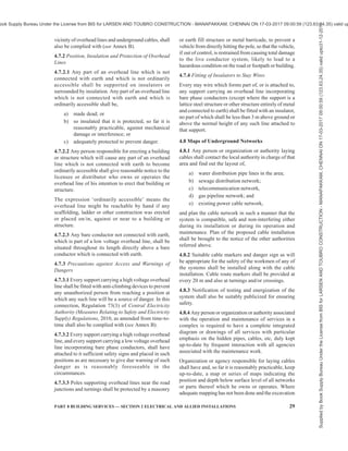
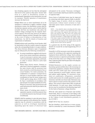
![PART 8 BUILDING SERVICES — SECTION 2 ELECTRICAL AND ALLIED INSTALLATIONS 31
NOTE — Additional safety precautions required to be observed
in HV installations shall also be kept in view.
In many cases there may be no choice available to the
consumer, as most of the licensees have formulated their
policy of correlating the supply voltage with the
connected load or the contract demand. Generally the
supply is at 240 V single phase up to 5 kVA,
415/240 V 3-phase from 5 kVA to 100 kVA, 11 kV (or
22 kV) for loads up to 5 MVA and 33 kV or 66 kV for
consumers of connected load or contract demand more
than 5 MVA.
5.2.3 In very large industrial buildings where heavy
electric demands occur at scattered locations, the
economics of electrical distribution at high voltage from
the main substation to other subsidiary transformer
substations or to certain items of plant, such as large
motors and furnaces, should be considered. The relative
economy attainable by use of medium or high voltage
distribution and high voltage plant is a matter of expert
judgment and individual assessment in light of
experience by a professionally qualified electrical
engineer.
5.3 Substation Equipment and Accessories
Substations require an approval by the Electrical
Inspectorate. Such approval is mandatory before
energizing the substation. It is desirable to get the
approval for the general layout, schematic layout,
protection plan, etc, before the start of the work from
the Inspectorate. All substation equipment and
accessories and materials, etc, shall conform to relevant
Indian Standards, wherever they exist, otherwise the
consumer (or his consultant) shall specify the standards
to which the equipment to be supplied confirms and
that shall be approved by the authority. Manufacturers
of equipment have to furnish certificate of conformity
as well as type test certificates for record, in addition
to specified test certificates for acceptance tests and
installation related tests for earthing, earth continuity,
load tests and tests for performance of protective gear.
5.3.1 Supply Company’s High Voltage Meter Board
In case of single point high voltage metering, energy
meters shall be installed in building premise as
per 4.2.2.1, at such a place which is readily accessible
to the owner/operator of the building and the Authority.
The supplier or owner of the installation shall provide
at the point of commencement of supply a suitable
isolating device fixed in a conspicuous position at not
more than 1.7 m above the ground so as to completely
isolate the supply to the building in case of emergency.
In this connection, Central Electricity Authority
(Installation and Operation of Meters) Regulations,
2006, as amended from time-to-time shall be complied
with.
5.3.2 High Voltage Switchgear
5.3.2.1 The selection of the type of high voltage
switchgear for any installation inter alia depends upon
the following:
a) Voltage of the supply system;
b) Prospective short-circuit current at the point
of supply;
c) Size and layout of electrical installation;
d) Accommodation available; and
e) Nature of industry.
Making and breaking capacity of switchgear shall be
commensurate with short-circuit potentialities of the
supply system and the supply authority shall be
consulted on this subject. HV switchgear and
controlgear shall conform to the accepted standards
[8-2(14)] and other relevant Indian Standards.
5.3.2.2 Guidelines on various types of switchgear
equipment and their choice for a particular application
shall be in accordance with good practice [8-2(12)].
5.3.2.3 In extensive installations of switchgear (having
more than four incoming supply cables or having more
than 12 circuit breakers), banks of switchgears shall be
segregated from each other in order to prevent spreading
of the risk of damage by fire or explosion arising from
switch failure. Where a busbar section switch is installed,
it shall also be segregated from adjoining banks in the
same way {see good practice [8-2(13)]}.
5.3.2.4 It should be possible to isolate any section from
the rest of the switchboards such that work might be
undertaken on this section without the necessity of
making the switchboard dead. Isolating switches used
for the interconnection of sections or for the purpose
of isolating circuit-breakers of other apparatus, shall
also be segregated within its compartment so that no
live part is accessible when work in a neighbouring
section is in progress.
5.3.2.5 In the case of double or ring main supply,
switchgears with interlocking arrangement shall be
provided to prevent simultaneous switching of two
different supply sources. Electrical and/or mechanical
interlocks may preferably be provided.
5.3.3 HV Cables
5.3.3.1 The sizing of the cable shall depend upon the
method of laying cable, current to be carried,
permissible maximum temperature it shall withstand,
voltage drop over the length of the cable, the
prospective short-circuit current to which the cable may
be subjected, the characteristics of the overload
protection gear installed, load cycle, thermal resistivity
of the soil and the operating voltage {see also good
practice [8-2(15)]}.
Supplied
by
Book
Supply
Bureau
Under
the
License
from
BIS
for
LARSEN
AND
TOUBRO
CONSTRUCTION
-
MANAPAKKAM,
CHENNAI
ON
17-03-2017
09:00:59
(123.63.24.35)
valid
upto31-12-2017
ook Supply Bureau Under the License from BIS for LARSEN AND TOUBRO CONSTRUCTION - MANAPAKKAM, CHENNAI ON 17-03-2017 09:00:59 (123.63.24.35) valid up](https://image.slidesharecdn.com/india-national-building-code-nbc-2016-vol-2-220512114536-12622fb6/85/india-national-building-code-nbc-2016-vol-2-pdf-173-320.jpg)
![32 NATIONAL BUILDING CODE OF INDIA 2016
5.3.3.2 All HV cables shall be installed in accordance
with good practice [8-2(15)]. The HV cables shall either
be laid on the cable rack/built-up concrete trenches/
tunnel/basement or directly buried in the ground
depending upon the specific requirement. When HV
cable is hanging/running below the basement ceiling
slab, the cable shall be laid in a fire rated enclosure/
cable tray. The advice of the cable manufacturer with
regard to installation, jointing and sealing should also
be followed.
5.3.4 High Voltage Bus Bar Trunking/Ducting
HV bus bar system is used for transporting power
between HV generators, transformers and the infeed
main switchgear of the main HV switchgear.
Generally three types of bus ducts, namely non-
segregated, segregated and isolated phase bus duct
are used. The non-segregated bus ducts consist of three
phase bus bars running in a common enclosure made
of steel or aluminium. The enclosure shall provide
safety for the operational personnel and shall reduce
chances of faults. HV interconnecting bus bar trunking
for a.c. voltage above 1 kV up to and including 36 kV
shall conform to accepted standard [8-2(16)]. The
enclosures shall be effectively grounded.
Segregated phase bus ducts are similar to non-
segregated phase ducts except that metal or isolation
barriers are provided between phase conductors to
reduce chances of phase to phase faults. However, it is
preferable to use metal barriers.
In the case of isolated bus ducts, each phase conductor
shall be housed in a separate non-magnetic enclosure.
The bus duct shall be made of sections which are
assembled together at site to make complete assembly.
The enclosure shall be of either round or square shape
and welded construction. The enclosures of all phases
in general should be supported on a common steel
structure.
Seismic supports shall be provided for busbar trunking
having continuous straight lengths of more than 24 m
at a single stretch.
The bus duct system shall be coordinated with
connecting switchgear so as to provide adequate
protection.
When busbar trunking is crossing different fire
compartments, they shall have fire barriers of same
rating as that of the compartment (see also Part 4 ‘Fire
and Life Safety’ of the Code).
5.3.5 Transformers
5.3.5.1 General design objective while selecting the
transformer(s) for a substation should be to provide at
least two or more transformers, so that a certain amount
of redundancy is built in, even if a standby system is
provided. The total installed transformer capacity shall
be at least 15 to 20 percent higher than the anticipated
maximum demand. With growing emphasis on energy
conservation, the system design is made for both
extremes of loading. During the periods of lowest load
in the system, it would be desirable to operate only one
transformer and to subsequently switch on the
additional transformers as the load increases during the
day. Total transformer capacity is generally selected
on the basis of present load, possible future load,
operation and maintenance cost and other system
conditions. The selection of the maximum size
(capacity) of the transformer is guided by the short-
circuit making and breaking capacity of the switchgear
used in the medium voltage distribution system.
Maximum size limitation is important from the aspect
of feed to a downstream fault. The transformers shall
conform to accepted standards [8-2(17)] and other
relevant Indian Standards.
5.3.5.2 For reasons of reliability and redundancy it is
normal practice to provide at least two transformers
for any important installation. Interlinking by tie lines
is an alternative to enhance reliability/redundancy in
areas where there are a number of substations in close
vicinity, such as a campus with three or four multi-
storeyed blocks, each with a substation. Ring main type
of distribution is preferred for complexes having a
number of substations.
5.3.6 Medium or Low Voltage Switchgear and
Controlgear and their Assemblies
5.3.6.1 The selection of the type of medium or low
voltage switchgear for any installation inter alia
depends upon the following:
a) Voltage of the distribution system;
b) Prospective circuit current at the point at
which the switchgear is proposed;
c) Prospective short-circuit current at which the
switchgear is proposed;
d) Accommodation available; and
e) Nature of industry.
The switchgear and controlgear and their assemblies
so selected shall comply with the relevant accepted
standards [8-2(18)], other relevant Indian Standards,
IEC 61439 (Part 1) : 2011 ‘Low-voltage switchgear and
controlgear assemblies — Part 1: General rules’ (under
publication as adopted Indian Standard) and IEC 61439
(Part 2): 2011 ‘Low-voltage switchgear and controlgear
assemblies — Part 2: Power switchgear and controlgear
assemblies’ (under publication as adopted Indian
Standard).
5.3.6.2 Switchgear (and its protective device) shall
Supplied
by
Book
Supply
Bureau
Under
the
License
from
BIS
for
LARSEN
AND
TOUBRO
CONSTRUCTION
-
MANAPAKKAM,
CHENNAI
ON
17-03-2017
09:00:59
(123.63.24.35)
valid
upto31-12-2017
ook Supply Bureau Under the License from BIS for LARSEN AND TOUBRO CONSTRUCTION - MANAPAKKAM, CHENNAI ON 17-03-2017 09:00:59 (123.63.24.35) valid up](https://image.slidesharecdn.com/india-national-building-code-nbc-2016-vol-2-220512114536-12622fb6/85/india-national-building-code-nbc-2016-vol-2-pdf-174-320.jpg)
![PART 8 BUILDING SERVICES — SECTION 2 ELECTRICAL AND ALLIED INSTALLATIONS 33
have breaking capacity not less than the anticipated
fault level in the system at that point. System fault
level at a point in distribution systems is
predominantly dependent on the transformer size and
its reactance. Parallel operation of transformers
increases the fault level.
5.3.6.3 Where two or more transformers are to be
installed in a substation to supply a medium voltage
distribution system, the distribution system shall be
divided into separate sections, each of which shall be
normally fed from one transformer only unless the
medium voltage switchgear has the requisite short-
circuit capacity. Provision may, however, be made to
interconnect separate sections, through a bus coupler
in the event of failure or disconnection of one
transformer. See 4.2 for details of location and
requirements of substation.
5.3.6.4 Isolation and controlling circuit breaker shall
be interlocked so that the isolator cannot be operated
unless the corresponding breaker is in open condition.
The choice between alternative types of equipment
may be influenced by the following considerations:
a) In certain installations supplied with electric
power from remote transformer substations,
it may be necessary to protect main circuits
with circuit-breakers operated by earth fault,
in order to ensure effective earth fault
protection.
b) Where large electric motors, furnaces or
other heavy electrical equipment is installed,
the main circuits shall be protected from
short-circuits by switch disconnector fuse or
circuit breakers. For motor protection, the
combination of contactor overload device
and fuse or circuit breakers shall have total
coordination at least for motor ratings up to
10 kW, and for ratings above 10 kW, it shall
be Type 2 coordination in accordance with
relevant part of accepted standards [8-2(18)].
Wherever necessary, back up protection and
earth fault protection shall be provided to the
main circuit.
c) Where means of isolating main circuits is
separately required, switch disconnector fuse
or switch disconnector may form part of main
switchboards.
5.3.6.5 It shall be mandatory to provide power factor
improvement capacitor at the substation bus. Suitable
capacitor may be selected in consultation with the
capacitor as well as switchgear manufacture
depending upon the nature of electrical load
anticipated on the system. Necessary switchgear/
feeder circuit breaker shall be provided for controlling
of capacitor bank.
Power factor of individual motor may be improved
by connecting individual capacitor banks in parallel.
For higher range of motors, which are running
continuously without much variation in load,
individual power factor correction at load end is
advisable.
NOTE — Care should be taken in deciding the kVAr rating
of the capacitor in relation to the magnetizing kVA of the
motor. Over rating of the capacitor may cause injury to the
motor and capacitor bank. The motor still rotating after
disconnection from the supply, may act as generator by self-
excitation and produce a voltage higher than supply voltage.
If the motor is again switched on before the speed has fallen
to about 80 percent of the normal running speed, the high
voltage will be superimposed on the supply circuits and will
damage both the motor and the capacitor.
As a general rule, the kVAr rating of the capacitor
should not exceed the no-load magnetizing kVA of
the motor.
Generally it will be necessary to provide an automatic
control for switching on the capacitors matching the
load power factor and the bus voltage. Such a scheme
will be necessary as capacitors permanently switched
in the circuit may cause over voltage at times of light
load. Capacitor panel shall be provided with adequate
ventilation facility.
5.3.6.6 Harmonics on the supply systems are
becoming a greater problem due to the increasing use
of electronic equipment, computer, fluorescent lamps,
LEDs and CFLs (both types have control/driver
circuits operating in switch mode), mercury vapour
and sodium vapour lighting, TV, microwave ovens,
latest air conditioners, refrigerators, controlled
rectifier and inverters for variable speed drives, power
electronics and other non-linear loads. Harmonics may
lead to almost as much current in the neutral as in the
phases. This current is almost third, fifth, seventh and
ninth harmonic. In such cases, phase rectification
devices may be considered at the planning stage itself
for the limits of harmonic voltage distortion.
With the wide spread use of thyristor and rectifier
based loads, there is a necessity of providing a full
size neutral; but this requirement is generally limited
to the 3-phase 4-wire distribution generally in
the 415/240 V.
5.3.6.7 MV/LV Bus bar chambers
Bus bar chambers, which feed two or more circuits,
shall be controlled by a main disconnector (TPN)
Supplied
by
Book
Supply
Bureau
Under
the
License
from
BIS
for
LARSEN
AND
TOUBRO
CONSTRUCTION
-
MANAPAKKAM,
CHENNAI
ON
17-03-2017
09:00:59
(123.63.24.35)
valid
upto31-12-2017
ook Supply Bureau Under the License from BIS for LARSEN AND TOUBRO CONSTRUCTION - MANAPAKKAM, CHENNAI ON 17-03-2017 09:00:59 (123.63.24.35) valid up](https://image.slidesharecdn.com/india-national-building-code-nbc-2016-vol-2-220512114536-12622fb6/85/india-national-building-code-nbc-2016-vol-2-pdf-175-320.jpg)
![PART 8 BUILDING SERVICES — SECTION 2 ELECTRICAL AND ALLIED INSTALLATIONS 35
fencing of such area shall be earthed efficiently.
Sufficient clearances as per 5.3.6.8 shall be provided
between the switchboard and the wall/fence.
5.3.6.11 Except main LV panel, it will be preferable to
locate the sub-panels/distribution boards/sub-meter
boards near the load centre. Further, it should be
ensured that these panels are easily approachable. The
panels should have clear access from common areas
excluding staircase.
Where the switchboard is erected in a room of a building
isolated from the source of supply or at a distance from
it, adequate means of control and isolation shall be
provided both near the boards and at the origin of
supply. Sufficient clearances as per 5.3.6.8 shall be
provided.
5.3.6.12 All switchboards shall be of metal clad totally
enclosed type or any insulated enclosed pattern.
5.3.7 Medium or Low Voltage Cables
5.3.7.1 The sizing of the cable shall depend upon the
current to be carried, method of laying cable,
permissible maximum temperature it shall withstand,
voltage drop over the length of the cable, the
prospective short-circuit current to which the cable may
be subjected, the characteristics of the overload
protection gear installed, load cycle, thermal resistivity
of the soil and the operating voltage {see also good
practice [8-2(11)]}.
It is desirable to use flame retardant cables and wires
in electrical distribution systems. Availability of flame
retardant low smoke and halogen cable may also be
noted and considered accordingly.
It is recommended to use four core cable in place of
three and half core to minimize heating of neutral core
due to harmonic content in the supply system and also
avoidance of overload failures. All cables shall be
installed in accordance with good practice [8-2(11)].
The advice of the cable manufacturer with regard to
installation, jointing and sealing should also be
followed.
In final circuits where cable size of 16 mm2
and below
are used, these shall be 4 core cables only to avoid the
possibility of neutral overload, (except for equipment
such as motors, heaters which offer balanced 3 phase
load and do not require a neutral connection. As a result
it is not desirable to use half-size neutral conductor as
possibility of neutral conductor overload due to
harmonics is likely. Larger feeders (size greater than
16 mm2
) may revert to use 3½ core cables.
5.3.7.2 Colour identification of cores of non-flexible
cables {see also good practice [8-2(19)]}
The colour of cores of non-flexible cables shall be in
accordance with the following:
Sl
No.
Function Colour Identification of Core of Rubber of
PVC Insulated Non-flexible Cable, or of
Sleeve or Disc to be Applied to Conductor
or Cable Code
(1) (2) (3)
i) Protective or earthing Green and yellow (see Note 1)
ii) Phase of a.c. single-phase circuit Red [or yellow or blue (see Note 2)]
iii) Neutral of a.c. single or three-phase circuit Black
iv) Phase R of 3-phase a.c. circuit Red
v) Phase Y of 3-phase a.c. circuit Yellow
vi) Phase B of 3-phase a.c. circuit Blue
vii) Positive of d.c. 2-wire circuit Red
viii) Negative of d.c. 2-wire circuit Black
ix) Outer (positive or negative) of d.c. 2-wire circuit
derived from 3-wire system
Red
x) Positive of 3-wire system (positive of 3-wire d.c.
circuit)
Red
xi) Middle wire of 3-wire d.c. circuit Black
xii) Negative of 3-wire d.c. circuit Blue
xiii) Functional earth-telecommunication Cream
NOTES
1 Bare conductors are also used for earthing and earth continuity conductors. But it is preferable to use insulated conductors with
green coloured insulation with yellow stripes.
2 As alternative to the use of red, yellow or blue colour may be used, if desired in large installations, up to the final distribution board.
3 For armoured PVC-insulated cables and paper-insulated cables, see relevant Indian Standard.
Supplied
by
Book
Supply
Bureau
Under
the
License
from
BIS
for
LARSEN
AND
TOUBRO
CONSTRUCTION
-
MANAPAKKAM,
CHENNAI
ON
17-03-2017
09:00:59
(123.63.24.35)
valid
upto31-12-2017
ook Supply Bureau Under the License from BIS for LARSEN AND TOUBRO CONSTRUCTION - MANAPAKKAM, CHENNAI ON 17-03-2017 09:00:59 (123.63.24.35) valid up](https://image.slidesharecdn.com/india-national-building-code-nbc-2016-vol-2-220512114536-12622fb6/85/india-national-building-code-nbc-2016-vol-2-pdf-177-320.jpg)
![36 NATIONAL BUILDING CODE OF INDIA 2016
5.3.7.3 Colour, identification of cores of flexible cables
and flexible cords {see also good practice [8-2(19)]}
The colour of cores of flexible cables and flexible cords
shall be in accordance with the following:
Sl
No.
Number
of
Cores
Function of
Core
Colour(s) of
Core
(1) (2) (3) (4)
i) 1 Phase
Neutral
Protective or
earthing
Brown1)
(Light) Blue
Green and
yellow
ii) 2 Phase
Neutral
Brown
(Light) Blue1)
iii) 3 Phase
Neutral
Protective or
earthing
Brown
(Light) Blue1)
Green and
yellow
iv) 4 or 5 Phase
Neutral
Protective or
earthing
Brown or
black1)
(Light) Blue1)
Green and
yellow
1)
Certain alternatives are allowed in wiring regulations.
5.3.8 MV/LV Bus bar Trunking/Rising Mains
5.3.8.1 Where heavy loads and/or multiple distribution
feeders are required to be supplied, busbar/rising main
systems are preferred. The busbars are available for
continuous run from point to point or with tap offs at
standard intervals and have to be chosen as per specific
requirement. Seismic supports shall be provided for bus
trunking having continuous straight lengths of more than
24 m at a single stretch. There are following two types
of MV/LV bus duct systems for power distribution:
a) Conventional type; and
b) Compact and sandwich type.
5.3.8.1.1 Conventional type bus duct
These are used for large power handling between
transformer and switchgear or between switchgear and
large power loads such as compressor drive motor, etc.
This type is generally used in plant rooms, riser shafts,
substations, etc. These are generally air insulated with
intermediate ceramic support insulators enclosed in a
metallic enclosure, which should be earthed. They have
the least amount of combustible material. However,
when these are crossing different fire compartments,
they shall have fire barriers of same rating as that of
the compartment (see also Part 4 ‘Fire and Life Safety’
of the Code).
Conventional type bus ducts with non-metallic
enclosures are also available. However, such bus ducts
shall be used only, if essential and with appropriate
additional care.
5.3.8.1.2 Compact type bus duct
Compact type bus ducts are used within areas of the
building which have space restrictions, etc, for aesthetic
and functional reasons. These are either air insulated
or sandwich type. They may be used in false ceiling
spaces or even in corridors and shafts for distribution
without any false ceiling as they provide an aesthetically
acceptable finish to merge with other building elements
such as beams, ducts or pipes in functional buildings.
The insulation material in such ducts are generally glass
fibre tape or epoxy encapsulation in combination with
ceramic supports/spacers. These bus ducts should be
duly enclosed by a metallic enclosure, which should
be earthed.
In case of compact air insulated type bus ducts crossing
different fire compartments, they shall have fire barriers
of same rating as that of the compartment (see also
Part 4 ‘Fire and Life Safety’ of the Code).
5.3.8.2 The bus duct system shall be coordinated with
connecting switchgear so as to provide adequate
protection.
5.3.8.3 Seismic supports shall be provided for busbar
trunking having continuous straight lengths of more
than 24 m at a single stretch.
5.3.8.4 Where the number of individual units/flats/
shops/offices on a floor in a building are more than 24,
multiple rising mains are recommended for power
distribution.
5.3.8.5 The low voltage bus bar trunking shall conform
to accepted standard [8-2(20)].
5.4 Reception and Distribution of Main Supply
5.4.1 Control at Point of Commencement of Supply
5.4.1.1 The supplier shall provide a suitable metering
switchgear in each conductor of every service line other
than an earthed or earth neutral conductor or the earthed
conductor of a concentric cable within a consumer’s
premises, in an accessible position and such metering
switchgear shall be contained within adequately
enclosed fireproof receptacle. Where more than one
consumer is supplied through a common service line,
such consumer shall be provided with an independent
metering switchgear at the point of rigid junction to
the common service. Every electric supply line other
than the earthed or earthed neutral conductor of any
system or the earthed external conductor of a concentric
cable shall be protected by a suitable switchgear by its
Supplied
by
Book
Supply
Bureau
Under
the
License
from
BIS
for
LARSEN
AND
TOUBRO
CONSTRUCTION
-
MANAPAKKAM,
CHENNAI
ON
17-03-2017
09:00:59
(123.63.24.35)
valid
upto31-12-2017
ook Supply Bureau Under the License from BIS for LARSEN AND TOUBRO CONSTRUCTION - MANAPAKKAM, CHENNAI ON 17-03-2017 09:00:59 (123.63.24.35) valid up](https://image.slidesharecdn.com/india-national-building-code-nbc-2016-vol-2-220512114536-12622fb6/85/india-national-building-code-nbc-2016-vol-2-pdf-178-320.jpg)
![PART 8 BUILDING SERVICES — SECTION 2 ELECTRICAL AND ALLIED INSTALLATIONS 37
owner. In this connection, Regulation 14 and 41 of
Central Electricity Authority (Measures Relating to
Safety and Electricity Supply) Regulations, 2010, as
amended from time-to-time shall also be complied with
(see Annex B).
In case of high rise buildings, the supplier or owner of
the installation shall provide at the point of
commencement of supply a suitable isolating device
with cut-out or breaker to operate on all phases except
neutral in the 3-phase, 4-wire circuit and fixed in a
conspicuous position at not more than 1.7 m above the
ground so as to completely isolate the supply to the
building in case of emergency. In this connection,
Regulation 36 of Central Electricity Authority
(Measures Relating to Safety and Electricity Supply)
Regulations, 2010, as amended from time-to-time shall
also be complied with (see Annex B).
The supplier shall provide and maintain on the
consumer’s premises for the consumer’s use, a suitable
earthed terminal in an accessible position at or near
the point of commencement of supply. In this
connection, Regulation 16 of Central Electricity
Authority (Measures Relating to Safety and Electricity
Supply) Regulations, 2010, as amended from time-to-
time shall also be complied with (see Annex B).
No cut-out, link or switch other than a linked switch
arranged to operate simultaneously on the earthed or
earthed neutral conductor and live conductor shall be
inserted or remain inserted in any earthed or earthed
neutral conductor of a two wire-system or in any earthed
or earthed neutral conductor of a multi-wire system or
in any conductor connected thereto. This requirement
shall however not apply in case of,
a) a link for testing purposes, or
b) a switch for use in controlling a generator or
transformer.
In this connection, Regulation 15 (ii) of Central
Electricity Authority (Measures Relating to Safety and
Electricity Supply) Regulations, 2010, as amended from
time-to-time shall also be complied with (see Annex B).
The neutral shall also be distinctly marked.
5.4.1.2 The main switch shall be easily accessible and
situated as near as practicable to the termination of
service line.
5.4.1.3 Where the conductors include an earthed
conductor of a two-wire system or an earthed neutral
conductor of a multi-wire system or a conductor which
is to be connected thereto, an indication of a permanent
nature shall be provided for identification in accordance
with Regulation 15 (i) of Central Electricity Authority
(Measures Relating to Safety and Electricity Supply)
Regulations, 2010, as amended from time-to-time (see
Annex B).
5.4.1.4 Energy meters
5.4.1.4.1 Energy meters conforming to accepted
standards [8-2(21)] and other relevant Indian Standards
shall be installed in all buildings at such a place which
is readily accessible to the owner/operator/occupant of
the building and the Authority. Meters should not be
located at an elevated area or a depressed area that does
not have access by means of a stairway of normal rise.
The height of meter display shall be between 750 mm
and 1 800 mm. In case the meter is provided with a
secondary display unit, this requirement applies to the
secondary display unit only. A minimum clearance of
50 mm should be maintained around the meter itself
for better inspection. This includes the space between
two meters, or between meter and the mounting box,
or between two mounting boxes as the case may be.
The energy meters should either be provided with a
protecting covering, enclosing it completely except the
glass window through which the readings are noted or
should be mounted inside a completely enclosed panel
provided with hinged arrangement for locking.
Additionally, for outdoor installations, the meters and
associated accessories shall be protected by appropriate
enclosure of level of protection IP 55 and ensuring
compliance with above conditions. The enclosure
should preferably be light coloured.
In large multi-storeyed buildings, installation of a large
number of energy meters at the ground floor (or first
basement) switch-room for the convenience of the
meter-reader poses high fire hazard. More than 24
energy meters on one switchboard is undesirable. In
such cases, where number of energy meters to be
installed for feeding exceeds 24, energy meters shall
be installed at each floor and therefore, the rising main
(bus trunking) with tapping point at individual floor
shall be provided for meters.
The energy meters shall be protected by suitable circuit
breaker. The provisions of 5.3.6.8 shall apply in case
of energy meters installed in boards.
5.4.1.4.2 Main sources of energy, as given below shall
be metered, as required at entry into the premise/control
panel:
1) Utility grid points (high voltage/medium
voltage/low voltage),
2) Captive generator sets, and
3) On-site renewable energy system (if installed/
operational).
5.4.1.4.3 Testing, evaluation, installation and
maintenance of energy meters shall be in accordance
with the good practice [8-2(22)].
5.4.1.4.4 Centralized metering system
Smart metering and energy monitoring in a centralized
Supplied
by
Book
Supply
Bureau
Under
the
License
from
BIS
for
LARSEN
AND
TOUBRO
CONSTRUCTION
-
MANAPAKKAM,
CHENNAI
ON
17-03-2017
09:00:59
(123.63.24.35)
valid
upto31-12-2017
ook Supply Bureau Under the License from BIS for LARSEN AND TOUBRO CONSTRUCTION - MANAPAKKAM, CHENNAI ON 17-03-2017 09:00:59 (123.63.24.35) valid up](https://image.slidesharecdn.com/india-national-building-code-nbc-2016-vol-2-220512114536-12622fb6/85/india-national-building-code-nbc-2016-vol-2-pdf-179-320.jpg)
![38 NATIONAL BUILDING CODE OF INDIA 2016
metering system are used to monitor, measure, and
control the demand of electrical loads in a building. These
systems are designed specifically for the control and
monitoring of those facilities in a building which have
significant electrical consumption, such as heating,
ventilation, air conditioning, lifts, pumps, and lighting
installations at multiple locations in a campus. The scope
may span from a single building to a group of buildings,
such as residential apartments under common ownership,
large multi-storeyed buildings, malls, university
campuses, office buildings, retail store networks,
factories, or any building with multi-tenanted occupancy.
These systems provide metering, submetering and
monitoring functions to allow facility and building
managers to gather data and insight that allow them to
make more informed decisions about demand
management and demand control across their sites.
For such buildings with centralized metering, several
main meters and sub-meters with following
requirements should be provided:
a) Main meters should be digital energy meters
with high accuracy, high sampling rates and
power quality parameters, that is, harmonics,
etc, for meters installed at incomer level.
b) Separate sub-meters should be provided for
all energy end uses and functional areas that
individually account for reasonable energy
consumption in the building. These may
include, but are not limited to, sub-meters for
HVAC system; common area lighting, raw
power, UPS, other common utility; lifts and
escalators, pumps, external and internal
lighting, individual units/flats/shops/ offices;
etc.
c) The sub-meters should be able to
communicate data for monitoring. At a
minimum, the sub-metering infrastructure
should facilitate the aggregation of total
energy use.
d) Adequate smart metering and energy
monitoring infrastructure should be installed
in order to help monitor operational energy
use and costs and to enable continuous energy
performance improvement.
Smart metering and energy monitoring system that can
display the following parameters should be installed
with two-way communicable smart meters:
1) Hourly energy demand and use;
2) Energy breakdown and mix and energy
consumption patterns;
3) Power quality analysis;
4) Energy consumption by process, department,
building, floor, etc;
5) Comparison of actual energy use with targets
or historical trends and benchmark energy key
performance indicators; and
6) Reporting on energy efficiency achieved.
These systems should also have the ability to utilize
near-real-time or time-of-use pricing through
integration of smart meters with the monitoring and
control system. The system should be capable of
supporting predictive demand for better demand
management and proactive demand control.
5.4.1.4.5 The Central Electricity Authority (Installation
and Operation of Meters) Regulations 2006, as
amended from time-to-time shall also be complied with.
5.4.2 Main Switches and Switchboard
5.4.2.1 All main switches shall be either of metal-clad
enclosed pattern or of any insulated enclosed pattern
which shall be fixed at close proximity to the point of
entry of supply. Every switch shall have suitable ingress
protection level rating (IP), so that its operation is
satisfactory and safe in the environment of the
installation.
NOTE — Woodwork shall not be used for the construction or
mounting of switches and switch boards installed in a building.
5.4.2.2 Location
The main switchboard shall comply with the following
requirements relating to its location:
a) The location of the main board should be such
that it is easily accessible to firemen and other
personnel to quickly disconnect the supply in
case of emergencies. If the room is locked for
security reasons, means of emergency access,
by schemes such as break glass cupboard,
shall be incorporated.
b) Main switch board shall be installed in rooms
or fire safe cupboards so as to safeguard
against operation by unauthorized personnel.
Otherwise the main switch board shall have
lock and key facility for small installations in
residences or other occupancies having
sanctioned loads less than 5 kW.
c) Switchboards shall be placed only in dry
situations and in ventilated rooms and they
shall not be placed in the vicinity of storage
batteries or exposed to chemical fumes.
d) In damp situation or where inflammable or
explosive dust, gas or vapour is likely to be
present, the switchboard shall be totally
enclosed and shall have adequate degree of
ingress protection (IP). In some cases
flameproof enclosure may be necessitated by
particular circumstances [see 8-2(23)].
Supplied
by
Book
Supply
Bureau
Under
the
License
from
BIS
for
LARSEN
AND
TOUBRO
CONSTRUCTION
-
MANAPAKKAM,
CHENNAI
ON
17-03-2017
09:00:59
(123.63.24.35)
valid
upto31-12-2017
ook Supply Bureau Under the License from BIS for LARSEN AND TOUBRO CONSTRUCTION - MANAPAKKAM, CHENNAI ON 17-03-2017 09:00:59 (123.63.24.35) valid up](https://image.slidesharecdn.com/india-national-building-code-nbc-2016-vol-2-220512114536-12622fb6/85/india-national-building-code-nbc-2016-vol-2-pdf-180-320.jpg)
![PART 8 BUILDING SERVICES — SECTION 2 ELECTRICAL AND ALLIED INSTALLATIONS 39
e) Switchboards shall not be erected above gas
stoves or sinks, or within 2.5 m of any washing
unit in the washing rooms or laundries, or in
bathrooms, lavatories or toilets, or kitchens.
f) In case of switchboards unavoidably fixed in
places likely to be located outdoors, exposed
to weather, to drip, or to abnormal moist
temperature, the outer casing shall be
weatherproof and shall be provided with
glands or bushings or adopted to receive
screwed conduit, according to the manner in
which the cables are run. The casing as well
as cable entries shall have suitable IP ratings
according to the installation.
g) Adequate illumination shall be provided for
all working spaces around the switchboards.
h) Easy access to the enclosure around
switchgear is essential to enable easy and safe
operation and maintenance. The provisions as
given in 5.3.6.8 including requirements for
sufficient clearances shall be complied with.
5.4.2.3 Metal-clad switchgear shall be mounted on any
of the following types of boards:
a) Hinged-type metal boards — These shall
consist of a box made of sheet metal not less
than 2 mm thick and shall be provided with a
hinged cover to enable the board to swing
open for examination of the wiring at the back.
The board shall be securely fixed to the wall
by means of proper nuts and bolts designed
to take weight of the switch board and shall
be provided with a locking arrangement and
an earthing and neutral stud or bus. All wires
passing through the metal board shall be
protected by cable termination glands at the
entry hole. The earth stud should
commensurate with the size of earth lead/
leads. Alternatively, metal boards may be
made of suitable size iron angle section of
minimum size 35 mm × 35 mm × 6 mm or
iron channel section of minimum size 35 mm
x 25 mm x 6 mm frame work suitably mounted
on front with a 3 mm thick mild steel plate
and on back with 1.5 mm thick mild steel
sheet. No apparatus shall project beyond any
edge of panel. No fuse body shall be mounted
within 25 mm of any edge of the panel.
NOTE — Such type of boards are particularly
suitable for small switchboard for mounting metal-
clad switchgear connected to supply at low voltages.
b) Fixed-type metal boards — These shall
consist of an angle or channel iron frame fixed
on the wall or on floor and supported on the
wall at the top, if necessary.
NOTE — Such type of boards are suitable for both
small and large switchboards. They are particularly
suitable for large switchboards for mounting number
of switchgears or high capacity metal-clad
switchgear or both in an arrangement which do not
require rear access.
c) Protected-type switchboard — A protected
switchboard is one where all of the switchgear
and conductors are protected by metal or
halogen free plastic enclosures. They may
consist of a metal/plastic cubicle panel, or an
iron frame upon which metal-clad switchgears
are mounted. They usually consist of a main
switch, bus bars and circuit breakers or fuses
controlling outgoing circuits.
d) Outdoor-type switchboard — An outdoor-type
switchboard is one which is totally enclosed
and UV ray protected and having high ingress
protection against dust and moisture and
vermin-proof and high impact resistance
(IP 55 or higher and IK 10). Such
switchboards are of cubicle type and also
provide high impact resistance. Cubicle type
boards shall be with hinged doors interlocked
with switch-operating mechanisms. The doors
of these switchboards shall have facility to
ensure that it is always in closed conditions.
All such switches shall bear labels indicating
their functions.
NOTE — Such switchboards shall be located away
from areas likely to be crowded by the public.
Open type switchboards wherever existing in old
buildings shall be phased out and replaced with
protected-type switchboards with suitable circuit
breakers.
5.4.2.4 Recessing of boards
Where so specified, the switchboards shall be recessed
in the wall. Ample room shall be provided at the back
for connection and at the front between the switchgear
mountings (see 5.3.6.8).
5.4.2.5 Marking of apparatus {see also good practices
[8-2(24)]}
Where a board is connected to voltage higher than
250 V, all the apparatus mounted on it shall be marked
with the following colours to indicate the different poles
or phases to which the apparatus or its different
terminals may have been connected:
a) Alternating current (three-phase) system:
Phase 1 – red, Phase 2 – yellow and Phase 3 –
blue; and 1 Neutral – black
b) Direct current (three-wire system):
2 outer wire, Positive – red and Negative –
blue; and 1 Mid wire (Neutral) – black
Supplied
by
Book
Supply
Bureau
Under
the
License
from
BIS
for
LARSEN
AND
TOUBRO
CONSTRUCTION
-
MANAPAKKAM,
CHENNAI
ON
17-03-2017
09:00:59
(123.63.24.35)
valid
upto31-12-2017
ook Supply Bureau Under the License from BIS for LARSEN AND TOUBRO CONSTRUCTION - MANAPAKKAM, CHENNAI ON 17-03-2017 09:00:59 (123.63.24.35) valid up](https://image.slidesharecdn.com/india-national-building-code-nbc-2016-vol-2-220512114536-12622fb6/85/india-national-building-code-nbc-2016-vol-2-pdf-181-320.jpg)
![PART 8 BUILDING SERVICES — SECTION 2 ELECTRICAL AND ALLIED INSTALLATIONS 41
complying with the accepted standards [8-2(25)] with
current rated according to their starting load, wiring,
MCB, etc, shall be designed for special equipment
space heaters, air conditioners, heat pumps, VRF, etc.
For feeding final single phase domestic type of loads
or general office loads it is advisable to introduce
additional cables if required to allow lowering of short
circuit rating of the switchgear required at user end.
Use of hand held equipment fed through flexible cords
is safe.
5.4.4.4 The circuits for lighting of common area shall
be separate. For large halls 3-wire control with
individual control and master control installed near the
entrance shall be provided for effective conservation
of energy. Occupancy sensors, movement sensors, lux
level sensors, etc, may also be considered as switching
options for lights, fans, TV, etc, for different closed
spaces (see also Part 11 ‘Approach to Sustainability’
of the Code).
5.4.4.5 Where daylight is abundantly available,
particularly in large halls, lighting in the area near the
windows likely to receive daylight shall have separate
controls for lights, so that they can be switched off/
automatically reduce intensity selectively when daylight
is adequate, while keeping the lights in the areas remote
from the windows on (see also Part 11 ‘Approach to
Sustainability’ of the Code).
5.4.4.6 Circuits for socket outlets may be kept separate
from circuits feeding fans and lights. Normally, fans
and lights may be wired on a common circuit. In large
spaces, circuits for fans and lights may also be
segregated. Lights may have group control in large halls
and industrial areas. While providing group control,
consideration may be given for the nature of use of the
area lit by a group. Consideration has to be given for
the daylight utilization, while grouping, so that a group
feeding areas near windows receiving daylight can be
selectively switched off during daylight period.
5.4.4.7 The load on any low voltage sub-circuit shall
not exceed 3 000 W. In case of a new installation, all
circuits and sub-circuits shall be designed with an initial
load of about 2 500 W, so as to allow a provision of
20 percent increase in load due to any future
modification. Power sub-circuits shall be designed
according to the load, where the circuit is meant for a
specific equipment. Good practice is to limit a circuit
to a maximum of three sockets, where it is expected
that there will be diversity due to use of very few sockets
in large spaces (example sockets for use of vacuum
cleaner). General practice is to limit it to two sockets
in a circuit, in both residential and non-residential
buildings and to provide a single socket on a circuit
for a known heavy load appliance such as air
conditioner, cooking range, etc.
5.4.4.8 In wiring installations at special places like
construction sites, stadia, shipyards, open yards in
industrial plants, etc, where a large number of high
wattage lamps may be required, there shall be no
restriction of load on any circuit but conductors used
in such circuits shall be of adequate size for the load
and proper circuit protection shall be provided. The
distribution boards (DBs) used in these areas shall be
of UV resistant, double insulated type with IP 66 or
higher degree of protection. Power tools and other
temporary equipment connected to these DBs shall be
sufficiently protected against electrical faults. Insulated
IP 66 sockets complying with the accepted standards
[8-2(25)] used in these DBs shall have interlocking
facility in addition to protection to ensure safe plugging
and unplugging of these equipment.
5.4.5 Location of Distribution Boards
a) The distribution boards shall be located as
near as possible to the centre of the load they
are intended to control.
b) These shall be fixed on suitable stanchion or
wall and shall be accessible for replacement/
reset of protective devices, and shall not be
more than 1.8 m from floor level.
c) These shall be of either metal-clad type, or
polycarbonate enclosure of minimum IP 42.
But, if exposed to weather or damp situations,
these shall be of the weatherproof type
conforming to IP 55 and, if installed where
exposed to explosive dust, vapour or gas, these
shall be of flameproof type in accordance with
accepted standards [8-2(26)]. In corrosive
atmospheres, these shall be treated with anti-
corrosive preservative or covered with suitable
plastic compound.
d) Where two and/or more distribution boards
feeding low voltage circuits are fed from a
supply of medium voltage, the metal case shall
be marked ‘Danger 415 Volts’ and identified
with proper phase marking and danger marks.
e) Each shall be provided with a circuit list giving
diagram of each circuit which it controls and
the current rating of the circuit and size of fuse
element.
f) In wiring branch distribution board, total load
of consuming devices shall be divided as far
as possible evenly between the number of
ways in the board leaving spare circuits for
future extension.
g) Distribution board shall not be located at
structural expansion joints of the building.
h) Distribution board/other electrical outlets shall
have a minimum calculated separation
distance from lightning protection down-
Supplied
by
Book
Supply
Bureau
Under
the
License
from
BIS
for
LARSEN
AND
TOUBRO
CONSTRUCTION
-
MANAPAKKAM,
CHENNAI
ON
17-03-2017
09:00:59
(123.63.24.35)
valid
upto31-12-2017
ook Supply Bureau Under the License from BIS for LARSEN AND TOUBRO CONSTRUCTION - MANAPAKKAM, CHENNAI ON 17-03-2017 09:00:59 (123.63.24.35) valid up](https://image.slidesharecdn.com/india-national-building-code-nbc-2016-vol-2-220512114536-12622fb6/85/india-national-building-code-nbc-2016-vol-2-pdf-183-320.jpg)
![42 NATIONAL BUILDING CODE OF INDIA 2016
conductors to avoid flash over in case of
lightning.
j) Walls with flushed distribution boards shall
have adequate support behind and surrounding
so that there is no physical weight on the
distribution board of the civil structure around.
Electrical switch sockets, etc, shall also be
avoided to be mounted behind the distribution
board to avoid touching the board from
behind.
5.4.6 Protection of Circuits
a) Appropriate protection shall be provided at
switchboards, distribution boards and at all
levels of panels for all circuits and sub-circuits
against short circuit, over-current and other
parameters as required. The protective device
shall be capable of interrupting maximum
prospective short circuit current that may
occur, without danger. The ratings and settings
of fuses and the protective devices shall be
coordinated so as to afford selectivity in
operation and in accordance with accepted
standards [8-2(27)].
b) Where circuit-breakers are used for protection
of a main circuit and of the sub-circuits
derived therefrom, discrimination in operation
may be achieved by adjusting the protective
devices of the sub-main circuit-breakers to
operate at lower current settings and shorter
time-lag than the main circuit-breaker.
c) Where HRC type fuses are used for back-up
protection of circuit- breakers, or where HRC
fuses are used for protection of main circuits,
and circuit-breakers for the protection of sub-
circuits derived there from, in the event of
short-circuits protection exceeding the short-
circuits protection exceeding the short-circuits
capacity of the circuit-breakers, the HRC fuses
shall operate earlier than the circuit-breakers;
but for smaller overloads within the short-
circuit capacity of the circuit-breakers, the
circuit-breakers shall operate earlier than the
HRC fuse blows.
d) If rewireable type fuses are used to protect
sub-circuits derived from a main circuit
protected by HRC type fuses, the main circuit
fuse shall normally blow in the event of a
short-circuit or earth fault occurring on sub-
circuit, although discrimination may be
achieved in respect of overload currents. The
use of rewireable fuses is restricted to the
circuits with short-circuit level of 4 kA; for
higher level either cartridge or HRC fuses
shall be used. However, use of rewireable fuse
is not desirable, even for lower fault level
areas. MCB’s provide a better and dependable
protection, as their current setting is not
temperable.
e) A fuse carrier shall not be fitted with a fuse
element larger than that for which the carrier
is designed.
f) The current rating of a fuse or circuit breaker
shall not exceed the current rating of the
smallest cable in the circuit protected by the
fuse.
g) Every fuse shall have its own case or cover
for the protection of the circuit and an indelible
indication of its appropriate current rating in
an adjacent conspicuous position.
h) All distribution board or panel incomer may
be protected by a surge protection device, if
found necessary (see 11). Separate HRC fuse/
CB with proper enclosure may be required in
series with the surge protection device with
main incomer. Back-up fuse/CB shall be of
the capacity not lower than that recommended
by the SPD manufacturer. Short circuit
withstand capability of the SPDs should be
coordinated with the HRC fuse/CB and SPD
should be selected to be matching the fault
power expected/calculated at that point.
5.4.7 Cascading, Discrimination and Limitation
Cascading and discrimination in switchgear
downstream and upstream shall be designed and
maintained such that the continuity of power in case of
any abnormal conditions such as overload, short circuit
and earth faults, etc is maintained and only faulty circuit
is isolated and power is made available to other loads.
Cascading technique allows the designer to select
circuit breakers of lower breaking capacities. Utilizing
the current limiting effect of the incoming breaker,
outgoing breaker can sustain the higher faults than its
capacity and even maintain the discrimination.
5.5 Protection Class of Equipment and Accessories
The class of ingress protection (IP) and protection
against mechanical impact (IK) {see also good practice
[8-2(6)] and IEC 62262:2002 ‘Degrees of protection
provided by enclosures for electrical equipment against
external mechanical impacts (IK code)’} shall be
specific depending on the requirement at the place of
installation.
5.6 Voltage and Frequency of Supply
It should be ensured that all equipment connected to
the system including any appliances to be used on it
are suitable for the voltage and frequency of supply of
the system. The nominal values of low and medium
voltage systems in India are 240 V and 415 V a.c.,
respectively, and the frequency is 50 Hz.
Supplied
by
Book
Supply
Bureau
Under
the
License
from
BIS
for
LARSEN
AND
TOUBRO
CONSTRUCTION
-
MANAPAKKAM,
CHENNAI
ON
17-03-2017
09:00:59
(123.63.24.35)
valid
upto31-12-2017
ook Supply Bureau Under the License from BIS for LARSEN AND TOUBRO CONSTRUCTION - MANAPAKKAM, CHENNAI ON 17-03-2017 09:00:59 (123.63.24.35) valid up](https://image.slidesharecdn.com/india-national-building-code-nbc-2016-vol-2-220512114536-12622fb6/85/india-national-building-code-nbc-2016-vol-2-pdf-184-320.jpg)
![PART 8 BUILDING SERVICES — SECTION 2 ELECTRICAL AND ALLIED INSTALLATIONS 43
NOTE — The design of the wiring system and the sizes of the
cables should be decided taking into account following factors:
a) Voltage drop — This should be kept below
6 percent to ensure proper functioning of all
electrical appliances and equipment including
motors;
b) Thermal limit based current carrying capacity
of the cable with appropriate derating factors
applicable to the installation conditions;
c) Capacity to withstand the let through fault
current based on the fault level and the
controlling switchgear disconnection
characteristics.
5.7 Rating of Cables and Equipment
5.7.1 The current-carrying capacity of different types
of cables shall be chosen in accordance with good
practice [8-2(28].
5.7.2 The current ratings of switches for domestic and
similar purposes are 6 A, 16 A, 20 A and 25 A.
5.7.3 The current ratings of isolators and normal duty
switches and composite units of switches and fuses shall
be selected from one of the following values:
16, 25, 32, 63, 100, 160, 200, 320, 400, 500, 630,
800, 1 000 and 1 250 A.
5.7.4 The ratings of rewireable and HRC fuses shall be
in accordance with good practice [8-2(29)].
5.7.5 The current ratings of miniature circuit-breakers
shall be chosen from the values given below:
6, 10, 16, 20, 25, 32, 40, 50, 63, 80, 100 and 125 A.
5.7.6 The current ratings of moulded case circuit
breakers shall be chosen from the values given below:
100, 125, 160, 200, 250, 315, 400, 630, 800, 1 000,
1 250 and 1 600A.
5.7.7 The current ratings of air circuit-breakers shall
be chosen from the values given below:
630, 800, 1 000, 1 250, 1 600, 2 000, 2 500, 3 200,
4 000A and 6 300 A.
5.7.8 The current ratings of the distribution fuse board
shall be selected from one of the following values:
6, 16, 25, 32, 63 and 100 A.
5.8 Installation Circuits
5.8.1 The nominal cross-sectional area of copper phase
conductors in a.c. circuits and of live conductors in
d.c. circuits shall be not less than the values specified
below:
Sl
No.
Type of Circuit Minimum
Copper Wire
Size
Number of Circuits
(1) (2) (3) (4)
i) Lighting 1.5 mm2
2 or more
ii) Socket-outlets, 6 A 2.5 mm2
Any number
Areas such as kitchens and laundries 3 × double
socket-outlets per circuit. Other areas up to 12
double socket-outlets
iii) Signaling and control circuits 0.5 mm2
(see Note 1)
—
iv) Socket-outlets, 16 A 2.5 mm2
1
v) Water heater 3 kW 2.5 mm2
1
vi) Heaters or electric equipment
more than or equal to 3 kW
4.0 mm2
1
vii) Free standing electric range
Separate oven and/or cook top
4.0 mm2
1
viii) Air conditioner 1.5 t 4.0 mm2
1
ix) Permanently connected
appliances including
dishwashers, heaters, etc
2.5 mm2
1 above 10 A. Up to 10 A can be wired as part
of a socket-outlet circuit
x) Appliance rated 3 kW6 kW 6.0 mm2
—
xi) Submains to garage or out-
building
2.5 mm2
1 for each
xii) Mains cable — It should be based on demand load/peaking
loads and future loading.
NOTE — In multi-core flexible cables containing 7 or more cores and in signalling control circuits intended for electronic equipment
a minimum nominal cross -sectional area of 0.1 mm 2
is permitted.
Supplied
by
Book
Supply
Bureau
Under
the
License
from
BIS
for
LARSEN
AND
TOUBRO
CONSTRUCTION
-
MANAPAKKAM,
CHENNAI
ON
17-03-2017
09:00:59
(123.63.24.35)
valid
upto31-12-2017
ook Supply Bureau Under the License from BIS for LARSEN AND TOUBRO CONSTRUCTION - MANAPAKKAM, CHENNAI ON 17-03-2017 09:00:59 (123.63.24.35) valid up](https://image.slidesharecdn.com/india-national-building-code-nbc-2016-vol-2-220512114536-12622fb6/85/india-national-building-code-nbc-2016-vol-2-pdf-185-320.jpg)
![PART 8 BUILDING SERVICES — SECTION 2 ELECTRICAL AND ALLIED INSTALLATIONS 45
Sl
No.
Circuits Minimum Wire Size Wire Colour
(1) (2) (3) (4)
vii)
viii)
Cooking hobs
Separate ovens
2 + E cable
1.5 mm2
2 + E cable
4 mm2
(stranded conductors)
Red-Black-Green or
Green/Yellow
ix) Electric range 2 + E cable
6 mm2
(stranded conductors)
Red-Black- Green or
Green/Yellow
x) Mains 2 wire cable
16 mm2
(stranded conductors)
Red-Black
xi) Main equipotential bonding wire Conduit wire
4 mm2
(stranded conductors)
Green or Green/Yellow
xii) Main earth wire Conduit wire
6 mm2
(stranded conductors)
Green or Green/Yellow
NOTES
1 2 + E is also known as twin and earth.
2 Earth wire can be as per the following:
a) Green/Yellow throughout their length with, in addition, light blue markings at the terminations, or
b) Light blue throughout their length with, in addition, green/yellow markings at the terminations.
3 The above sizes are recommendatory and shall be modified as per voltage drop, starting current, distance from DB, etc.
5.8.6 Requirements for Physical Protection of
Underground Cables
Sl
No.
Protective
Element
Specifications
(1) (2) (3)
i) Bricks (a) 100 mm minimum
width
(b) 25 mm thick
(c) sand cushioning 100
mm and sand cover
100 mm
ii) Concrete slabs At least 50 mm thick
iii) Plastic slabs
(polymeric
cover strips)
Fibre reinforced
plastic
At least 10 mm thick,
depending on properties
and has to be matched
with the protective
cushioning and cover
iv) PVC conduit or
PVC pipe or
stoneware pipe
or hume pipe
The pipe diameter
should be such so that
the cable is able to
easily slip down the pipe
v) Galvanized pipe The pipe diameter
should be such so that
the cable is able to
easily slip down the pipe
The trench shall be backfilled to cover the cable initially
by 200 mm of sand fill; and then a plastic marker strip
shall be put over the full length of cable in the trench.
The marker signs shall be provided where any cable
enters or leaves a building. This will identify that there
is a cable located underground near the building. The
trench shall then be completely filled. If the cables rise
above ground to enter a building or other structure, a
mechanical protection such as a GI pipe or PVC pipe
for the cable from the trench depth to a height of 2.0 m
above ground shall be provided.
5.9 Lighting and Levels of Illumination
5.9.1 General
Lighting installation shall take into consideration many
factors on which the quality and quantity of artificial
lighting depends. Recent practice in illumination is to
provide the required illumination with a large number
of light sources (not of higher illumination level) instead
of fewer number of light sources of higher illumination
level, to produce higher uniformity in illumination level.
Now a wide variety of light sources, such as, fluorescent
lamps [tubular (TL) and compact (CFL)], light emitting
diodes (LED) and induction lighting are available in
addition to the incandescent lamps (GLS and halogen),
for application in buildings. Most of them are
competitive when applied in the segment for which a
particular type is well suited.
With the increase in energy costs and awareness of the
need to conserve energy for the protection of the
Supplied
by
Book
Supply
Bureau
Under
the
License
from
BIS
for
LARSEN
AND
TOUBRO
CONSTRUCTION
-
MANAPAKKAM,
CHENNAI
ON
17-03-2017
09:00:59
(123.63.24.35)
valid
upto31-12-2017
ook Supply Bureau Under the License from BIS for LARSEN AND TOUBRO CONSTRUCTION - MANAPAKKAM, CHENNAI ON 17-03-2017 09:00:59 (123.63.24.35) valid up](https://image.slidesharecdn.com/india-national-building-code-nbc-2016-vol-2-220512114536-12622fb6/85/india-national-building-code-nbc-2016-vol-2-pdf-187-320.jpg)
![46 NATIONAL BUILDING CODE OF INDIA 2016
environment, lighting design is becoming complex.
With the developments in the types of light sources
and their control systems now available, lighting design
goes with the concept of better light with less energy
and least impact on environment.
Automatic lighting control schemes may be considered
to have efficient utilization of lights. Automatic controls
can take care of the switching off when the space served
has no activity or is illuminated by daylight.
5.9.2 Electrical Installations for Lighting
The concepts or needs of energy conservation today
require more lights to be provided so that different sets of
lightsareusedtolightuptheareaofactivitytotherequired
higherleveloflightingneededfortheactivityandprovide
a general minimum background level of lighting. Any
space requires two or three different combination of
lighting sets associated with the activity and this may
require the wiring to be provided to accommodate the
lighting groups in different circuits with group controls,
automatic controls and remote controls.
Availability of LED lights with a wide range from 1 W
to 100 W allows designers to provide spot task lighting
of a high illumination level combined with a general
space lighting of low illumination. As light follows the
inverse square law, provision of the light source close
to the task reduces the energy need.
Lighting demand for buildings should be considered
as per type of building. Where nothing is specified, for
lighting demand of any type of building a maximum of
13 W/m2
of all built-up areas including balconies.
Covered parking areas may be considered at 3.23 W/m2
including balconies, service areas, corridors, etc, may
be considered with very basic diversity of 80 percent
to 100 percent. Power requirements shall be considered
at least 55 W/m2
with an overall diversity not exceeding
50 percent. These shall be excluding defined loads such
as lifts, plumbing system, fire fighting systems,
ventilation requirement, etc.
While incandescent lamps (GLS or halogen) does not
require any control gear, other light sources such as
tubular fluorescent lamps, compact fluorescent lamps,
mercury vapour lamps, sodium vapour lamps, metal
halide lamps and light emitting diode (LED) lamps have
non-linear characteristics and require specifically made
control gear for each type of lamp for their proper
operation. In some cases the control gear is integral
with the lamp and in some it is with light fitting and in
some it is external. The electrical installation and wiring
has to take this into account and provide appropriate
space for such control gear. There will be heat emission,
introduction of harmonics etc, and they also consume
some energy. The electrical and lighting system design
has to keep this aspect in the wiring design and
installation. Control gear contributes or influences
energy conservation significantly and due care should
be taken to ensure a proper choice.
5.9.3 Principles of Lighting
When considering the function of artificial lighting,
attention shall be given to the following principle
characteristics before designing an installation:
a) Illumination and its uniformity;
b) Special distribution of light. This includes a
reference to the composition of diffused and
directional light, direction of incidence, the
distribution of luminances and the degree of
glare;
c) Colour of the light and colour rendition;
d) Natural light sources, if possible such as light
tubes; and
e) System wattage of the luminaire proposed.
5.9.4 The variety of purposes which have to be kept in
mind while planning the lighting installation may be
broadly grouped as:
a) Industrial buildings and processes;
b) Offices, schools and public buildings;
c) Surgeries and hospitals; and
d) Hostels, restaurants, shops and residential
buildings.
5.9.4.1 It is important that appropriate levels of
illumination for these and the types and positions of
fittings determined to suit the task and the disposition
of the working planes.
5.9.5 For detailed requirements for lighting and lighting
design and installations, reference shall be made to
National Lighting Code. For specific requirements for
lighting of special occupancies, reference shall be made
to good practice [8-2(30)] and the National Lighting
Code.
5.9.6 Energy Conservation
Energy conservation may be achieved by using the
following:
a) Energy efficient lamps, chokes, ballast, etc,
for lighting equipment.
b) Efficient switching systems such as remote
sensors, infrared switches, master switches,
occupancy sensors, light sensors, light
automation, remote switches, etc for switching
‘ON’ and ‘OFF’ of lighting circuits.
c) Properly made/connected joints/contacts to
avoid loose joints leading to loss of power.
5.10 In locations where the system voltage exceeds
650 V, as in the case of industrial locations, for details
of design and construction of wiring installation,
Supplied
by
Book
Supply
Bureau
Under
the
License
from
BIS
for
LARSEN
AND
TOUBRO
CONSTRUCTION
-
MANAPAKKAM,
CHENNAI
ON
17-03-2017
09:00:59
(123.63.24.35)
valid
upto31-12-2017
ook Supply Bureau Under the License from BIS for LARSEN AND TOUBRO CONSTRUCTION - MANAPAKKAM, CHENNAI ON 17-03-2017 09:00:59 (123.63.24.35) valid up](https://image.slidesharecdn.com/india-national-building-code-nbc-2016-vol-2-220512114536-12622fb6/85/india-national-building-code-nbc-2016-vol-2-pdf-188-320.jpg)
![PART 8 BUILDING SERVICES — SECTION 2 ELECTRICAL AND ALLIED INSTALLATIONS 47
reference may be made to good practice [8-2(11)].
5.11 Guideline for Electrical Layout in Residential
Buildings
For guidelines for electrical installation in residential
buildings, reference may be made to good practice
[8-2(31)].
A typical distribution scheme in a residential building
with separate circuits for lights and fans and for power
appliances is given in Fig. 3.
5.12 For detailed information regarding the installation
of different electrical equipment, reference may be
made to good practice [8-2(32)].
6 WIRING
6.1 Provision for Maximum Load
All conductors, switches and accessories shall be of
such size as to be capable of carrying, without their
respective ratings being exceeded, the maximum
current which will normally flow through them.
6.1.1 Estimation of Load Requirements
In estimating the current to be carried by any conductor
the following ratings shall be taken, unless the actual
values are known or specified for these elements:
Sl
No.
Element Rating
W
(1) (2) (3)
i) Incandescent lamp 60
ii) Ceiling fan 60
iii) Table fan 60
iv) 6 A socket outlet 100, unless the
actual value of
loads are specified
v) 16 A socket outlet 1 000, unless the
actual value of
loads are specified
vi) Fluorescent light:
Length :
a) 600 mm
b) 1 200 mm
c) 1 500 mm
25
50
90
vii) High pressure
mercury vapour
(HPMV) lamps, high
pressure sodium
vapour (HPSV)
lamps
According to their
capacity, control
gear losses shall be
also considered as
applicable
viii) Compact fluorescent
lamp (CFL)
20
ix) Light emitting diode
(LED)
10
Sl
No.
Element Rating
W
(1) (2) (3)
x) Exhaust fan 50
xi) Geyser (storage type) 2 000
xii) Geyser (instant) 3 000
xiii) Computer point 150
xiv) Computer (laptop) 50
xv) Printer, laser 1 500
xvi) Printer, inkjet 70
xvii) Kitchen outlet 1 500
xviii) Air conditioner:
1 TR
1.5 TR
2 TR
2.5 TR
1 250
1 875
2 500
3 200
6.1.2 Electrical installation in a new building shall
normally begin immediately on the commencement of
the main structural building work and before finishing
work such as plastering has begun except in the case of
surface wiring which can be carried out after the plaster
work. Usually, no installation work should start until
the building is reasonably weatherproof, but where
electric wiring is to be concealed within the structures
as may be the case with a reinforced concrete building,
the necessary conduits and ducts shall be positioned
firmly by tying the conduit to the reinforcement before
concreting. Care should be taken to avoid use of
damaged conduit or ducts, the conduits end shall be
given suitable anti-corrosive treatment and holes
blocked off by putties or caps to protect conduits from
getting blocked. All conduit openings and junction box
openings, etc shall be properly protected against entry
of mortar, concrete, etc, during construction.
6.2 Selection of Size of Conductors
The size of conductors of circuits shall be so selected
that the drop in voltage from consumer’s terminals in a
public supply (or from the bus-bars of the main
switchboard controlling the various circuits in a private
generation plant) to any point on the installation does
not exceed three percent of the voltage at the consumer’s
terminals (or at two bus-bars as these may be) when the
conductors are carrying the maximum current under the
normal conditions of service. The overall voltage drop
from the transformer end to consumer’s final distribution
board shall not exceed six percent.
6.2.1 If the cable size is increased to reduce voltage
drop in the circuit, the rating of the cable shall be
sufficient to carry the current which the circuit is
designed for. In each circuit or sub-circuit the fuse/
circuit-breaker shall be selected to match the current
rating of the circuit to ensure the desired protection.
Supplied
by
Book
Supply
Bureau
Under
the
License
from
BIS
for
LARSEN
AND
TOUBRO
CONSTRUCTION
-
MANAPAKKAM,
CHENNAI
ON
17-03-2017
09:00:59
(123.63.24.35)
valid
upto31-12-2017
ook Supply Bureau Under the License from BIS for LARSEN AND TOUBRO CONSTRUCTION - MANAPAKKAM, CHENNAI ON 17-03-2017 09:00:59 (123.63.24.35) valid up](https://image.slidesharecdn.com/india-national-building-code-nbc-2016-vol-2-220512114536-12622fb6/85/india-national-building-code-nbc-2016-vol-2-pdf-189-320.jpg)
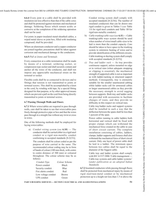
![PART 8 BUILDING SERVICES — SECTION 2 ELECTRICAL AND ALLIED INSTALLATIONS 51
6.6.4 Every joint in a cable shall be provided with
insulation not less effective than that of the cable cores
and shall be protected against moisture and mechanical
damage. Soldering fluxes which remain acidic or
corrosive at the completion of the soldering operation
shall not be used.
For joints in paper-insulated metal-sheathed cables, a
wiped metal sleeve or joint box, filled with insulating
compound, shall be provided.
Where an aluminum conductor and a copper conductor
are joined together, precautions shall be taken against
corrosion and mechanical damage to the conductors.
6.6.5 Pull at Joints and Terminals
Every connection at a cable termination shall be made
by means of a terminal, soldering socket, or
compression type socket and shall securely contain and
anchor all the wires of the conductor, and shall not
impose any appreciable mechanical strain on the
terminal or socket.
Flexible cords shall be so connected to devices and to
fittings that tension is not transmitted to joints or
terminal screws. This shall be accomplished by a knot
in the cord, by winding with tape, by a special fitting
designed for that purpose, or by other approved means
which can prevent a pull on the cord from being directly
transmitted to joints or terminal screws.
6.7 Passing Through Walls and Floors
6.7.1 Where wires/cables are required to pass through
walls, care shall be taken to see that wires/cables pass
freely through protective pipe or box and that the wires
pass through in a straight line without any twist or cross
in wires.
One of the following methods shall be employed for
laying wires/cables:
a) Conduit wiring system (see 6.10) — The
conductor shall be carried either in a rigid steel
conduit or a rigid non-metallic conduit
conforming to accepted standards [8-2(33)].
The conduits shall be colour coded as per the
purpose of wire carried in the same. The
recommended colour coding may be in form
of bands of colour (100 mm thick, with centre
to centre distance of 300 mm) or coloured
throughout. The colour scheme may be as
follows:
Conduit Type Colour Scheme
Power conduit Black
Security conduit Blue
Fire alarm conduit Red
Low voltage conduit Brown
UPS conduit Green
Conduit wiring system shall comply with
accepted standards [8-2(34)]. The number of
insulated conductors that can be drawn into
rigid conduit is given in Tables 1 (see Table
1A for rigid steel conduits and Table 1B for
rigid non-metallic conduits).
b) Cable trunking/cable ways (see 6.11) — Cable
trunking/cable ways system should be used
when number of wires/small cable sizes to be
laid is more than the conduit capacity. Care
should be taken to have space in the trunking
system to minimize heating of wires and to
provide identification of the different circuits.
Cable trunking or ducting system shall comply
with accepted standards [8-2(35)].
c) Tray and ladder rack — As tray provides
continuous support, unless mounted on edge
or in vertical runs (when adequate strapping
or clipping is essential), the mechanical
strength of supported cable is not as important
as with ladder-racking or structural support
methods. Consequently, tray is eminently
suitable for the smaller unarmoured cabling
while ladder racks call for armoured cables
or larger unarmoured cables as they provide
the necessary strength to avoid sagging
between supports. Both tray and ladder racks
are provided with accessories to facilitate
changes of route, and they provide no
difficulty in this respect on vertical runs.
Cable tray/ladder racks and support systems
shall be installed in such a way that the
deflection between the spans shall be less than
1 percent of the span.
Power cables running in cable ladders both
horizontal and vertical shall be fixed with
proper clamps which can withstand the
mechanical force created on the cable in case
of short circuit current. The complete
installation consisting of cables, ladders,
clamps, ladder supports and fixtures shall also
withstand the mechanical force of short circuit
current. Only one layer of power cable shall
be laid in a ladder. The minimum space
between two cables shall be equal to the
diameter of the biggest cable.
Cable tray and ladder system shall comply
with IEC 61537:2006 ‘Cable management —
Cable tray systems and cable ladder systems’
(under publication as an adopted Indian
Standard).
6.7.2 Insulated conductors while passing through floors
shall be protected from mechanical injury by means of
rigid steel/non-metal conduit or by mechanical
protection up to a height not less than 1.5 m above the
Supplied
by
Book
Supply
Bureau
Under
the
License
from
BIS
for
LARSEN
AND
TOUBRO
CONSTRUCTION
-
MANAPAKKAM,
CHENNAI
ON
17-03-2017
09:00:59
(123.63.24.35)
valid
upto31-12-2017
ook Supply Bureau Under the License from BIS for LARSEN AND TOUBRO CONSTRUCTION - MANAPAKKAM, CHENNAI ON 17-03-2017 09:00:59 (123.63.24.35) valid up](https://image.slidesharecdn.com/india-national-building-code-nbc-2016-vol-2-220512114536-12622fb6/85/india-national-building-code-nbc-2016-vol-2-pdf-193-320.jpg)
![PART 8 BUILDING SERVICES — SECTION 2 ELECTRICAL AND ALLIED INSTALLATIONS 53
covered with sheet metal protective covering,
the base of which is made flush with the plaster
or brickwork, as the case may be, or the wiring
shall be drawn through a conduit complying
with all requirements of conduit wiring system
(see 6.10).
b) Such protective coverings shall in all cases
be fitted on all down-drops within 1.5 m from
the floor.
6.9.4 Bends in Wiring
The wiring shall not in any circumstances be bent so as
to form a right angle but shall be rounded off at the
corners to a radius not less than six times the overall
diameter of the cable.
6.9.5 Passing Through Floors
All cables taken through floors shall be enclosed in an
insulated heavy gauge steel conduit extending 1.5 m
above the floor and flush with the ceiling below, or by
means of any other approved type of metallic covering.
The ends of all conduits or pipes shall be neatly bushed
with porcelain, wood or other approved material.
6.9.6 Passing Through Walls
The method to be adopted shall be according to good
practice. There shall be one or more conduits of
adequate size to carry the conductors [see 6.10.1(a)].
The conduits shall be neatly arranged so that the cables
enter them straight without bending.
6.9.7 Stripping of Outer Covering
While cutting and stripping of the outer covering of
the cables, care shall be taken that the sharp edge of
the cutting instrument does not touch the rubber or
PVC-sheathed insulation of conductors. The protective
outer covering of the cables shall be stripped off near
connecting terminals, and this protective covering shall
be maintained up to the close proximity of connecting
terminals as far as practicable. Care shall be taken to
avoid hammering on link clips with any metal
instruments, after the cables are laid. Where junction
boxes are provided, they shall be made moisture-proof
with an approved plastic compound.
6.9.8 Painting
If so required, the tough rubber-sheathed wiring shall,
after erection, be painted with one coat of oil-less paint
or distemper of suitable colour over a coat of oil-less
primer, and the PVC-sheathed wiring shall be painted
with a synthetic enamel paint of quick drying type.
6.10 Conduit Wiring System
Conduit wiring system shall comply with accepted
standards [8-2(34)]. Requirements relating to conduit
wiring system with rigid steel and non-metallic conduits
shall be as per 6.10.1 to 6.10.3.
6.10.1 Surface Conduit Wiring System with Rigid Steel
Conduits
a) Type and size of conduit — All conduit pipes
shall conform to accepted standards [8-2(36)],
finished with galvanized or enamelled surface.
All conduit accessories shall be of threaded
type and under no circumstance pin grip type
or clamp type accessories be used. No steel
conduit less than 16 mm in diameter shall be
used. The number of insulated conductors that
can be drawn into rigid steel conduit is given
in Tables 1A.
b) Bunching of cables — Unless otherwise
specified, insulated conductors of a.c. supply
and d.c. supply shall be bunched in separate
conduits. For lighting and small power outlet
circuits phase segregation in separate conduits
is recommended.
c) Conduit joints — Conduit pipes shall be joined
by means of screwed couplers and screwed
accessories only [see 8-2(37)]. In long distance
straight runs of conduit, inspection type
couplers at reasonable intervals shall be
provided or running threads with couplers and
jam-nuts (in the latter case the bare threaded
portion shall be treated with anti-corrosive
preservative) shall be provided. Threaded on
conduit pipes in all cases shall be between 11
mm and 27 mm long sufficient to accommodate
pipes to full threaded portion of couplers or
accessories. Cut ends of conduit pipes shall
have no sharp edges or any burrs left to avoid
damage to the insulation of conductors while
pulling them through such pipes.
d) Protection against dampness — In order to
minimize condensation or sweating inside the
tube, all outlets of conduit system shall be
properly drained and ventilated, but in such a
manner as to prevent the entry of insects as
far as possible.
e) Protection of conduit against rust — The
outer surface of the conduit pipes, including
all bends, unions, tees, conduit system shall
be adequately protected against rust
particularly when such system is exposed to
weather. In all cases, no bare threaded portion
of conduit pipe shall be allowed unless such
bare threaded portion is treated with anti-
corrosive preservative or covered with suitable
plastic compound.
f) Fixing of conduit — Conduit pipes shall be
fixed by heavy gauge saddles, secured to
Supplied
by
Book
Supply
Bureau
Under
the
License
from
BIS
for
LARSEN
AND
TOUBRO
CONSTRUCTION
-
MANAPAKKAM,
CHENNAI
ON
17-03-2017
09:00:59
(123.63.24.35)
valid
upto31-12-2017
ook Supply Bureau Under the License from BIS for LARSEN AND TOUBRO CONSTRUCTION - MANAPAKKAM, CHENNAI ON 17-03-2017 09:00:59 (123.63.24.35) valid up](https://image.slidesharecdn.com/india-national-building-code-nbc-2016-vol-2-220512114536-12622fb6/85/india-national-building-code-nbc-2016-vol-2-pdf-195-320.jpg)
![54 NATIONAL BUILDING CODE OF INDIA 2016
Table 1A Maximum Permissible Number of Single-Core Cables up to and including 1 100 V
that can be Drawn into Rigid Steel Conduits
[Clauses 6.7.1(a) and 6.10.1(a)]
Size of Cable Size of Conduit
mm
16 20 25 32 40 50 63
Number of Cables, Max
Sl
No.
Nominal
Cross-
Sectional
Area
mm2
Number
and
Diameter
(in mm) of
Wires
S B S B S B S B S B S B S B
(1) (2) (3) (4) (5) (6) (7) (8) (9) (10) (11) (12) (13) (14) (15) (16) (17)
i) 1.0 1/1.121)
5 4 7 5 13 10 20 14 — — — — — —
ii) 1.5 1/1.40 4 3 7 5 12 10 20 14 — — — — — —
iii) 2.5 1/1.80
3/1.061)
3 2 6 5 10 8 18 12 — — — — — —
iv) 4 1/2.24
7/0.851)
3 2 4 3 7 5 12 10 — — — — — —
v) 6 1/2.80
7/1.061)
2 — 3 2 6 5 10 8 — — — — — —
1/3.552)
— — 2 — 5 4 8 7 — — — — — —
vi) 10
7/1.401)
— — 2 — 4 3 6 5 8 6 — — — —
vii) 16 7/1.70 — — — — 2 — 4 3 7 6 — — — —
viii) 25 7/2.24 — — — — — — 3 2 5 4 8 6 9 7
ix) 35 7/2.50 — — — — — — 2 — 4 3 7 5 8 6
x) 50 19/1.80
7/3.0072)
— — — — — — — — 2 — 5 4 6 5
NOTES
1 The table shows the maximum capacity of conduits for the simultaneously drawing of cables. The columns headed S apply to runs
of conduit which have distance not exceeding 4.25 m between draw-in boxes, and which do not deflect from the straight by an angle
of more than 15°. The columns headed B apply to runs of conduit which deflect from the straight by an angle of more than 15°.
2 In case an inspection type draw-in box has been provided and if the cable is first drawn through one straight conduit, then through the
draw-in box, and then through the second straight conduit, such systems may be considered as that of a straight conduit even if the
conduit deflects through the straight by more than 15°.
3 Conductor sizes for cables and wires above and including 2.5 mm2
core size shall be multi-stranded.
1)
For copper conductors only.
2)
For aluminium conductors only.
suitable wood plugs or other plugs with screws
in an approved manner at an interval of not
more than 1 m, but on either side of couplers
or bends or similar fittings, saddles shall be
fixed at a distance of 300 mm from the centre
of such fittings. Conduit fittings shall be
avoided as far as possible on conduit system
exposed to weather; where necessary, solid
type fittings shall be used.
g) Bends in conduit — All necessary bends in
the system including diversion shall be done
by bending pipes; or by inserting suitable solid
or inspection type normal bends, elbows or
similar fittings; or fixing cast iron,
thermoplastic or thermosetting plastic material
inspection boxes, whichever is more suitable.
Radius of such bends in conduit pipes shall
be not less than 75 mm. No length of conduit
shall have more than the equivalent of four
quarter bends from outlet to outlet, the bends
at the outlets not being counted.
h) Outlets — All outlets for fittings, switches,
etc, shall be boxes of suitable metal or any
other approved outlet boxes for either surface
mounting or flush mounting system.
j) Conductors — All conductors used in conduit
wiring shall preferably be stranded. No single-
core cable of nominal cross-sectional area
greater than 130 mm2
enclosed along in a
conduit and used for alternating current.
k) Erection and earthing of conduit — The
conduit of each circuit or section shall be
completed before conductors are drawn in.
The entire system of conduit after erection
shall be tested for mechanical and electrical
continuity throughout and permanently
connected to earth conforming to the
requirements as already specified by means
of suitable earthing clamp efficiently fastened
to conduit pipe in a workman like manner for
a perfect continuity between each wire and
conduit. Gas or water pipes shall not be used
Supplied
by
Book
Supply
Bureau
Under
the
License
from
BIS
for
LARSEN
AND
TOUBRO
CONSTRUCTION
-
MANAPAKKAM,
CHENNAI
ON
17-03-2017
09:00:59
(123.63.24.35)
valid
upto31-12-2017
ook Supply Bureau Under the License from BIS for LARSEN AND TOUBRO CONSTRUCTION - MANAPAKKAM, CHENNAI ON 17-03-2017 09:00:59 (123.63.24.35) valid up](https://image.slidesharecdn.com/india-national-building-code-nbc-2016-vol-2-220512114536-12622fb6/85/india-national-building-code-nbc-2016-vol-2-pdf-196-320.jpg)
![PART 8 BUILDING SERVICES — SECTION 2 ELECTRICAL AND ALLIED INSTALLATIONS 55
as earth medium. If conduit pipes are liable to
mechanical damage they shall be adequately
protected.
m) Inspection type conduit fittings, such as
inspection boxes, draw boxes, bends, elbows
and tees shall be so installed that they can
remain accessible for such purposes as to
withdrawal of existing cables or the installing
of traditional cables.
6.10.2 Recessed Conduit Wiring System with Rigid Steel
Conduit
Recessed conduit wiring system shall comply with all
the requirements for surface conduit wiring system
specified in 6.10.1 (a) to 6.10.1 (k) and in addition,
conform to the requirements specified below:
a) Making of chase — The chase in the wall shall
be neatly made and be of ample dimensions
to permit the conduit to be fixed in the manner
desired. In the case of buildings under
construction, chases shall be provided in the
wall, ceiling, etc, at the time of their
construction and shall be filled up neatly after
erection of conduit and brought to the original
finish of the wall. In case of exposed brick/
rubble masonry work, special care shall be
taken to fix the conduit and accessories in
position along with the building work.
b) Fixing of conduit in chase — The conduit pipe
shall be fixed by means of staples or by means
of saddles not more than 600 mm apart. Fixing
of standard bends or elbows shall be avoided
as far as practicable and all curves maintained
by bending the conduit pipe itself with a long
radius which will permit easy drawing-in of
conductors. All threaded joints of rigid steel
conduit shall be treated with preservative
compound to secure protection against rust.
c) Inspection boxes — Suitable inspection boxes
shall be provided to permit periodical
inspection and to facilitate removal of wires,
if necessary. These shall be mounted flush with
the wall. Suitable ventilating holes shall be
provided in the inspection box covers. The
minimum sizes of inspection boxes shall be
75 mm × 75 mm.
d) Types of accessories to be used — All outlet,
such as switches and wall sockets, may be
either of flush mounting type or of surface
mounting type, as given below:
1) Flush mounting type — All flush
mounting outlets shall be of cast-iron or
mild steel boxes with a cover of insulating
material or shall be a box made of a
suitable insulating material. The switches
and other outlets shall be mounted on such
boxes. The metal box shall be efficiently
earthed with conduit by a suitable means
of earth attachment.
2) Surface mounting type — If surface
mounting type outlet box is specified, it
shall be of any suitable insulating material
and outlets mounted in an approved
manner.
The switches/socket outlets shall have
adequate IP rating for various utilizations.
6.10.3 Conduit Wiring System with Rigid Non-Metallic
Conduits
Rigid non-metallic conduits are used for concealed
conduit wiring.
6.10.3.1 Type and size
All non-metallic conduits used shall conform to
accepted standards [8-2(38)] and shall be used with
the corresponding accessories {see accepted standards
[8-2(39)]}. The conduits shall be circular or rectangular
cross-sections.
6.10.3.2 Bunching of cables
Conductors of a.c. supply and d.c. supply shall be
bunched in separate conduits. For lighting and small
power outlet circuits phase segregation in separate
circuits is recommended. The number of insulated
cables that may be drawn into the conduits are given in
Table 1 B. In Table 1B, the space factor does not exceed
40 percent.
6.10.3.3 Conduit Joints
Conduits shall be joined by means of couplers. Where
there are long runs of straight conduit, inspection type
couplers shall be provided at intervals. For conduit
fittings and accessories reference may be made to the
good practice [8-2(39)].
6.10.3.4 Fixing of conduit in chase
The conduit pipe shall be fixed by means of stapples
or by means of non-metallic saddles placed at not more
than 800 mm apart or by any other approved means of
fixing. Fixing of standard bends or elbows shall be
avoided as far as practicable and all curves shall be
maintained by sending the conduit pipe itself with a
long radius which will permit easy drawing in of
conductors. At either side of bends, saddles/stapples
shall be fixed at a distance of 150 mm from the centre
of bends.
6.10.3.5 Inspection boxes
Suitable inspection boxes to the nearest minimum
requirements shall be provided to permit periodical
inspection and to facilitate replacement of wires, if
Supplied
by
Book
Supply
Bureau
Under
the
License
from
BIS
for
LARSEN
AND
TOUBRO
CONSTRUCTION
-
MANAPAKKAM,
CHENNAI
ON
17-03-2017
09:00:59
(123.63.24.35)
valid
upto31-12-2017
ook Supply Bureau Under the License from BIS for LARSEN AND TOUBRO CONSTRUCTION - MANAPAKKAM, CHENNAI ON 17-03-2017 09:00:59 (123.63.24.35) valid up](https://image.slidesharecdn.com/india-national-building-code-nbc-2016-vol-2-220512114536-12622fb6/85/india-national-building-code-nbc-2016-vol-2-pdf-197-320.jpg)
![56 NATIONAL BUILDING CODE OF INDIA 2016
necessary. The inspection/junction boxes shall be
mounted flush with the wall or ceiling concrete. Where
necessary deeper boxes of suitable dimensions shall
be used. Suitable ventilating holes shall be provided in
the inspection box covers, where required.
6.10.3.6 The outlet boxes such as switch boxes,
regulator boxes and their phenolic laminated sheet
covers shall be as per requirements of 6.10.1 (h). They
shall be mounted flush with the wall.
6.10.3.7 Types of accessories to be used
All accessories such as switches, wall sockets, etc, may
be either flush mounting type or of surface mounting
type.
6.10.3.8 Bends in conduits
Wherever necessary, bends or diversions may be
achieved by bending the conduits or by employing
normal bends, inspection bends, inspection boxes,
elbows or similar fittings. Heat may be used to soften
the conduit for bending and forming joints in case of
plain conduits.
6.10.3.9 Outlets
In order to minimize condensation or sweating inside
the conduit, all outlets of conduit system shall be
properly drained and ventilated, but in such a manner
as to prevent the entry of insects.
6.11 Cable Trunking/Cable Ways
Cable trunking and ducting system of insulating
material are used for surface wiring. The number of
insulated conductors that can be drawn into cable
trunking and ducting system are given in Table 2.
7 FITTINGS AND ACCESSORIES
7.1 Ceiling Roses and Similar Attachments
7.1.1 A ceiling rose or any other similar attachment
shall not be used on a circuit the voltage of which
normally exceeds 250 V.
7.1.2 Normally, only one flexible cord shall be attached
to a ceiling rose. Specially designed ceiling roses shall
be used for multiple pendants.
7.1.3 A ceiling rose shall not embody fuse terminal as
an integral part of it.
7.2 Socket-Outlets and Plugs
Each 16 A socket-outlet provided in buildings for the
use of domestic appliances, such as, air conditioner and
water cooler shall be provided with its own individual
fuse, with suitable discrimination with back-up fuse or
miniature circuit-breaker provided in the distribution/
sub-distribution board. The socket-outlet shall not
necessarily embody the fuse as an integral part of it.
7.2.1 Each socket-outlet shall also be controlled by a
switch which shall preferably be located immediately
adjacent thereto or combined therewith.
7.2.2 The switch controlling the socket-outlet shall be
on the live side of the line.
Sizes of Cable Size of Conduit
mm
16 20 25 32 40 50
Sl
No.
Nominal Cross-
Sectional Area
mm2
Number and
Diameter (in mm)
of Wires
Number of Cables, Max
(1) (2) (3) (4) (5) (6) (7) (8) (9)
i) 1.0 1/1.121)
5 7 13 20 — —
ii) 1.5 1/1.40 4 6 10 14 — —
iii) 2.5 (1/1.80)
[3/1.061)
]
3 5 10 14 — —
iv) 4 (1/2.24)
[7/0.851)
]
2 3 6 10 14 —
v) 6 (1/2.80)
[7/1.401)
]
— 2 5 9 11 —
vi) 10 [1/3.552)
]
[7/1.401)
]
— — 4 7 9 —
vii) 16 7/1.70 — — 2 4 5 12
viii) 25 7/2.24 — — — 2 2 6
ix) 35 7/2.50 — — — — 2 5
7/3.002)
— — — — 2 5
x) 50
19/1.80 — — — — 2 3
1)
For copper conductors only.
2)
For aluminium conductors only.
Table 1B Maximum Permissible Number of 250 V Grade Single-Core Cables that may be
Drawn into Rigid Non-Metallic Conduits
[Clauses 6.7.1(a) and 6.10.3.2]
Supplied
by
Book
Supply
Bureau
Under
the
License
from
BIS
for
LARSEN
AND
TOUBRO
CONSTRUCTION
-
MANAPAKKAM,
CHENNAI
ON
17-03-2017
09:00:59
(123.63.24.35)
valid
upto31-12-2017
ook Supply Bureau Under the License from BIS for LARSEN AND TOUBRO CONSTRUCTION - MANAPAKKAM, CHENNAI ON 17-03-2017 09:00:59 (123.63.24.35) valid up](https://image.slidesharecdn.com/india-national-building-code-nbc-2016-vol-2-220512114536-12622fb6/85/india-national-building-code-nbc-2016-vol-2-pdf-198-320.jpg)
![PART 8 BUILDING SERVICES — SECTION 2 ELECTRICAL AND ALLIED INSTALLATIONS 57
7.2.3 Ordinary socket-outlet may be fixed at any
convenient place at a height above 200 mm from the
floor level and shall be away from danger of mechanical
injury.
NOTE — In situations where a socket-outlet is accessible to
children, it is necessary to install an interlocked plug and socket
or alternatively a socket-outlet which automatically gets
screened by the withdrawal of plug. In industrial premises
socket-outlet of rating 20 A and above shall preferably be
provided with interlocked type switch.
In case of public buildings, to facilitate operation of
switches/socket-outlets by persons with disabilities
and the elderly, these shall be installed at an accessible
height for reaching and operating, between 800 mm
and 1 100 mm above floor level and shall be located
at a minimum of 600 mm with a preference of
minimum 700 mm, from any internal corner (see also
B-7 of Part 3 ‘Development Control Rules and
General Building Requirements’ of the Code). They
shall be so fixed so as to be away from danger of
mechanical injury.
NOTE — As an exception, electrical wall socket outlets,
telephone points and TV sockets can be located at a minimum
height of 400 mm above floor level.
7.2.4 In an earthed system of supply, a socket-outlet
with plug shall be of three-pin or five-pin type with the
third or fifth terminal connected to the earth. When
such socket-outlets with plugs are connected to any
current consuming device of metal or any non-
insulating material or both, conductors connecting such
current-consuming devices shall be of flexible cord with
an earthing core and the earthing core shall be secured
by connecting between the earth terminal of plug and
the body of current-consuming devices.
In industrial premises three-phase and neutral socket-
outlets shall be provided with a earth terminal either of
pin type or scrapping type in addition to the main pins
required for the purpose.
7.2.5 In wiring installations for residential buildings,
metal clad switch, socket-outlet and plugs shall be used
for power wiring. For industrial and commercial
application socket outlets conforming to accepted
standards [8-2(25)] with suitable circuit breakers shall
be used.
NOTE — A recommended schedule of socket-outlets in a
residential building is given below:
Sl
No.
Location Number of
6 A Socket-
Outlets
Number of
16 A
Socket-
Outlets
(1) (2) (3) (4)
i) Bed room 2 to 6 2
ii) Living room 2 to 4 2
iii) Kitchen 2 to 8 2
iv) Dining room 2 to 4 2
v) Garage 1 1
vi) For refrigerator — 1
vii) For air conditioner — 1 for each
viii) Verandah 1 per
10 m2
1
ix) Bathroom 1 1
7.3 Lighting Fittings
7.3.1 A switch shall be provided for control of every
lighting fitting or a group of lighting fittings. Where
control at more than one point is necessary as many
two way or intermediate switches may be provided as
there are control points. See also 7.2.3.
7.3.2 In industrial premises, lighting fittings shall be
supported by suitable pipe/conduits, brackets fabricated
from structural steel, steel chains or similar materials
depending upon the type and weight of the fittings.
Table 2 Maximum Permissible Number of PVC Insulated 650/1 100 V Grade Aluminium/Copper Cable
Conforming to Accepted Standard [8-2(3)] that can be Drawn into Cable Trunking/Cable Ways
(Clause 6.11)
Sl
No.
Nominal Cross-
Sectional Area
of Conductor
mm2
10/15 mm ×
10 mm
20/15 mm ×
10 mm
25/15 mm ×
16 mm
32 mm ×
16 mm
40 mm ×
25 mm
40 mm ×
40 mm
(1) (2) (3) (4) (5) (6) (7) (8)
i) 1.5 3 5 6 8 12 18
ii) 2.5 2 4 5 6 9 15
iii) 4 2 3 4 5 8 12
iv) 6 — 2 3 4 6 9
v) 10 — 1 2 3 5 8
vi) 16 — — 1 2 4 6
vii) 25 — — — 1 3 5
viii) 35 — — — — 2 4
ix) 50 — — — — 1 3
x) 70 — — — — 1 2
Supplied
by
Book
Supply
Bureau
Under
the
License
from
BIS
for
LARSEN
AND
TOUBRO
CONSTRUCTION
-
MANAPAKKAM,
CHENNAI
ON
17-03-2017
09:00:59
(123.63.24.35)
valid
upto31-12-2017
ook Supply Bureau Under the License from BIS for LARSEN AND TOUBRO CONSTRUCTION - MANAPAKKAM, CHENNAI ON 17-03-2017 09:00:59 (123.63.24.35) valid up](https://image.slidesharecdn.com/india-national-building-code-nbc-2016-vol-2-220512114536-12622fb6/85/india-national-building-code-nbc-2016-vol-2-pdf-199-320.jpg)
![58 NATIONAL BUILDING CODE OF INDIA 2016
Where a lighting fitting is supported by one or more
flexible cords, the maximum weight to which the twin
flexible cords may be subjected shall be as follows:
Sl
No.
Nominal Cross-
Sectional Area
of Twin Cord
Maximum
Permissible
Weight
mm2
kg
(1) (2) (3)
i) 0.5 2
ii) 0.75 3
iii) 1.0 5
iv) 1.5 5.3
v) 2.5 8.8
vi) 4 14.0
7.3.3 No flammable shade shall form a part of lighting
fittings unless such shade is well protected against all
risks of fire. Celluloid shade or lighting fittings shall
not be used under any circumstances.
7.3.4 General and safety requirements for electrical
lighting fittings shall be in accordance with good
practice [8-2(40)].
7.3.5 The lighting fittings shall conform to accepted
standards [8-2(26)].
7.4 Fitting-Wire
The use of fitting-wire shall be restricted to the internal
wiring of the lighting fittings. Where fitting-wire is used
for wiring fittings, the sub-circuit loads shall terminate
in a ceiling rose or box with connectors from which
they shall be carried into the fittings.
7.5 Lampholders
Lampholders for use on brackets and the like shall be
in accordance with accepted standards [8-2(41)] and
all those for use with flexible pendants shall be provided
with cord grips. All lampholders shall be provided with
shade carriers. Where centre-contact Edison screw
lampholders are used, the outer or screw contacts shall
be connected to the ‘middle wire’, the neutral, the
earthed conductor of the circuit.
7.6 Outdoor Lamps
External and road lamps shall have weatherproof fittings
of approved design so as to effectively prevent the ingress
of moisture and dust. Flexible cord and cord grip
lampholders shall not be used where exposed to weather.
In verandahs and similar exposed situations where
pendants are used, these shall be of fixed rod type.
7.7 Lamps
All lamps unless otherwise required and suitably
protected, shall be hung at a height of not less than
2.5 m above the floor level. All electric lamps and
accessories shall conform to accepted standards
[8-2(42)]. Following shall also be ensured:
a) Portable lamps shall be wired with flexible
cord. Hand lamps shall be equipped with a
handle of moulded composition or other
material approved for the purpose. Hand
lamps shall be equipped with a substantial
guard attached to the lampholder or handle.
Metallic guards shall be earthed suitably.
b) A bushing or the equivalent shall be provided
where flexible cord enters the base or stem of
portable lamp. The bushing shall be of
insulating material unless a jacketted type of
cord is used.
c) All wiring shall be free from short circuits and
shall be tested for these defects prior to being
connected to the circuit.
d) Exposed live parts within porcelain fixtures
shall be suitably recessed and so located as to
make it improbable that wires will come in
contact with them. There shall be a spacing of
at least 125 mm between live parts and the
mounting plane of the fixture.
7.8 Fans, Regulators and Clamps
7.8.1 Ceiling Fans
Ceiling fans including their suspension shall conform
to accepted standards [8-2(43)] and to the following
requirements:
a) Control of a ceiling fan shall be through its
own regulator as well as a switch in series.
See also 7.2.3.
b) All ceiling fans shall be wired with normal
wiring to ceiling roses or to special connector
boxes to which fan rod wires shall be connected
and suspended from hooks or shackles with
insulators between hooks and suspension rods.
There shall be no joint in the suspension rod,
but if joints are unavoidable then such joints
shall be screwed to special couplers of 50 mm
minimumlengthandbothendsofthepipesshall
touch together within the couplers, and shall in
addition be secured by means of split pins;
alternatively, the two pipes may be welded. The
suspension rod shall be of adequate strength to
withstand the dead and impact forces imposed
on it. Suspension rods should preferably be
procured along with the fan.
c) Fan clamps shall be of suitable design
according to the nature of construction of
ceiling on which these clamps are to be fitted.
In all cases fan clamps shall be fabricated from
new metal of suitable sizes and they shall be
Supplied
by
Book
Supply
Bureau
Under
the
License
from
BIS
for
LARSEN
AND
TOUBRO
CONSTRUCTION
-
MANAPAKKAM,
CHENNAI
ON
17-03-2017
09:00:59
(123.63.24.35)
valid
upto31-12-2017
ook Supply Bureau Under the License from BIS for LARSEN AND TOUBRO CONSTRUCTION - MANAPAKKAM, CHENNAI ON 17-03-2017 09:00:59 (123.63.24.35) valid up](https://image.slidesharecdn.com/india-national-building-code-nbc-2016-vol-2-220512114536-12622fb6/85/india-national-building-code-nbc-2016-vol-2-pdf-200-320.jpg)
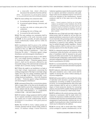
![PART 8 BUILDING SERVICES — SECTION 2 ELECTRICAL AND ALLIED INSTALLATIONS 61
intended for switching or control or protection of wiring
installations shall conform to the relevant Indian
Standards, wherever they exist.
7.12 Positioning of fans and light fittings shall be
chosen to make these effective without causing shadows
and stroboscopic effect on the working planes.
8 EARTHING
8.1 General
8.1.1 Earthing is an essential part of any electrical
installation, essential for the safety from electrical
shock, and fire and for operation of most of the
protective systems of the electrical installation. The
earthing provides the necessary reference of zero
potential and helps in activating the operation of the
circuit breaker provided for the safe disconnection of
power in the event of an abnormality in the flow of
current. Earthing systems, apart from addressing safety
from shock and fire, help in limiting the interference
between one appliance and the other. This is of
particular importance in the case of voice and data
communication devices. With the proliferation in
electrical/electronic gadgets and greater dependence
on voice and data communication systems, proper and
effective earthing or grounding is very important.
Earthing is also necessary for diverting the effects of
lightning strikes from the buildings and its contents,
including from sensitive equipment.
8.1.2 Different types of earth electrodes and different
types of earthing systems available. For low voltage and
medium voltage systems which apply to almost all
electrical systems of buildings, the common earthing
system followed is with the neutral solidly earthed at the
source. This system requires that there is always a
protective earth continuity conductor running all through
the system and all metal parts of electrical appliances
connected to an electrical system are connected to the
earth continuity conductor. The exception to this system
is the double insulated appliances which are connected
to the line and neutral and operate on low voltage (single
phase) and are also of low power consumption. All
appliances (other than double insulated devices) use the
earthing through the earth continuity conductor. Single
phase appliances use a 3-wire connection with line (live
wire), neutral (return path wire) and the earth-wire at
zero potential. Three phase appliances use a connection
with 4-wires for a load which does not require a neutral
connection or use a 5-wire connection if the appliance
requires a neutral connection. Care should be taken to
ensure that the earthing system, the earth continuity
conductor and in case of sockets plugs the earthing pin
are not disconnected.
8.1.3 Different earthing systems have features which
are suitable for different applications. Earthing system
adopted should be so selected so as to match with the
type of load, protection device, application, degree of
reliability, etc. For classification of electrical systems
based on the relationship of the source, and of exposed-
conductive parts of the installation, to earth, see 2.1.75.
8.2 Selection and Design of Earthing System
8.2.1 Earthing shall generally be carried out in
accordance with the requirements of Regulation 16, 41
and 48 of Central Electricity Authority (Measures
relating to Safety and Electricity Supply) Regulations,
2010 as amended from time-to-time (see Annex B) and
good practice [8-2(44)] and the relevant regulations of
the Electricity Supply Authority concerned.
8.2.2 Conductors and earth electrodes in an earthing
system shall be so designed and constructed that in
normal use their performance is reliable and without
danger to persons and surrounding equipment. Earthing
system shall be designed such as to have touch potential
and step potential as specified in good practice
[8-2(44)]. The choice of a material depends on its ability
to match the particular application requirement. The
requirements for earthing arrangements are intended
to provide a connection to earth which,
a) is reliable and suitable for the protective
requirements of the installation;
b) can carry earth fault currents and protective
conductor currents to earth without danger
from thermal, thermo-mechanical and
electromechanical stresses and from electric
shock arising from these currents;
c) if relevant, is also suitable for functional
requirements; and
d) is suitable for the foreseeable external
influences {see good practice [8-2(44)] and
IEC 60364-5-51:2005 ‘Electrical installations
of buildings — Part 5-51: Selection and
erection of electrical equipment — Common
rules’}, for example, mechanical stresses and
corrosion.
8.2.3 The main earthing system of an electrical
installation shall consist of,
a) an earth electrode, (electrode can be one
vertical rod/pipe/buried plate or an earth mat
with several vertical installations or a ring
earthing with vertical installations.
b) a main earthing wire;
c) an earth bar (located on the main switchboard
for small installation and installed in the wall/
room in case of large industrial electronic
installations) for the connection of the main
earthing wire, protective earthing wires and/
or bonding wires within the installation; and
Supplied
by
Book
Supply
Bureau
Under
the
License
from
BIS
for
LARSEN
AND
TOUBRO
CONSTRUCTION
-
MANAPAKKAM,
CHENNAI
ON
17-03-2017
09:00:59
(123.63.24.35)
valid
upto31-12-2017
ook Supply Bureau Under the License from BIS for LARSEN AND TOUBRO CONSTRUCTION - MANAPAKKAM, CHENNAI ON 17-03-2017 09:00:59 (123.63.24.35) valid up](https://image.slidesharecdn.com/india-national-building-code-nbc-2016-vol-2-220512114536-12622fb6/85/india-national-building-code-nbc-2016-vol-2-pdf-203-320.jpg)
![62 NATIONAL BUILDING CODE OF INDIA 2016
d) a removable link, which effectively
disconnects the neutral bar from the earth bar.
NOTE — The requirements of (c) and (d) shall be carried out
by a licensed electrician as part of the switchboard installation.
8.2.4 The main earthing wire connection shall,
a) be mechanically and electrically sound;
b) be protected against damage, corrosion, and
vibration;
c) not place any strain on various parts of the
connection;
d) not damage the wire or fittings; and
e) be secured at the earth electrode.
8.2.4.1 The main earthing wire termination shall be
readily accessible at the earth electrode except
for 8.2.20. As far as possible, all earth connections,
except exothermically welded, shall be visible for
inspection.
8.2.5 Consideration shall be given to the earthing
arrangements where currents with high frequencies are
expected to flow (see 444 of IEC 60364-4-44:2007
‘Low-voltage electrical installations — Part 4-44:
Protection for safety — Protection against voltage
disturbances and electromagnetic disturbances’).
8.2.6 Protection against electric shock (see IEC 60364-
4-41 ‘Low-voltage electrical installations — Part 4-
41: Protection for safety — Protection against electric
shock’), shall not be adversely affected by any
foreseeable change of the earth electrode resistance (for
example, due to corrosion, drying or freezing).
8.2.7 Where the supply to an installation is at high or
extra high voltage, requirements concerning the
earthing arrangements of the high or extra high voltage
supply and of the low-voltage installation shall also
comply with 442 of IEC 60364-4-44:2007 ‘Low-
voltage electrical installations — Part 4-44: Protection
for safety — Protection against voltage disturbances
and electromagnetic disturbances’.
8.2.8 A permanent fitting (like a screwed-down plastic
label or copper label, or one that can be threaded onto
the cable) shall be used at the connection point that is
clearly marked with the words: ‘EARTHING LEAD
— DO NOT DISCONNECT’ or ‘EARTHING
CONDUCTOR — DO NOT DISCONNECT’.
8.2.9 All medium voltage equipment shall be earthed
by two separate and distinct connections with earth.
The contact area of earth conductor/plate shall be
determined in accordance with good practice
[8-2(44)].
8.2.9.1 The 415/240 V, 4-wire, 3-phase systems are
normally operated with the neutral solidly earthed at
source. At medium voltage, Central Electricity
Authority regulations require that the neutral be earthed
by two separate and distinct connections with earth.
Source in the case of a substation (such as 11 kV/415 V)
will be the neutral(s) of the transformer(s). Neutral
conductor shall be of the same size as the phase
conductor.
NOTE — Neutral conductor of half the size of the phase
conductor was permitted in earlier installations. But with the
proliferation of equipment using non-linear devices and
consequent increase in harmonics, the neutral will carry a
current more than the notional out-of-balance current and
therefore neutral conductor shall be of the same size as the
phase conductor.
8.2.10 In the case of high and extra high voltages, the
neutral points shall be earthed by not less than two
separate and distinct connections to earth, each having
its own electrode at the generating station or substation
and may be earthed at any other point provided no
interference is caused by such earthing. The neutral
may be earthed through suitable impedance. Neutral
earthing conductor shall be sized as to have a current
carrying capacity not less than the phase current.
8.2.11 For industrial/commercial installations having
a transformer within the facility, soil resistivity of the
place of installation shall be measured as per good
practice [8-2(44)] and recorded. For the adopted type
of earth electrode configuration, earth resistance of each
electrode configuration shall be calculated and recorded
based on good practice [8-2(44)].
8.2.12 It is recommended that a drawing showing the
main earth connection and earth electrodes be prepared
for each installation.
8.2.13 Conductors, other than live conductors, and any
other parts intended to carry a fault current shall be
capable of carrying that current without attaining an
excessive temperature.
8.2.14 Earth system shall be so devised that the testing
of individual earth electrode is possible {except for
installations according to 5.3.6 of good practice
[8-2(45)]}. It is recommended that the value of any earth
system resistance shall be such as to conform to the
degree of shock protection desired. For measuring
purposes, the joint shall be capable of being opened with
the aid of a tool. In normal use it shall remain closed.
8.2.15 No addition to the current-carrying system, either
temporary or permanent, shall be made which will
increase the maximum available earth fault current or
its duration until it has been ascertained that the existing
arrangement of earth electrodes, earth bus-bar, etc, are
capable of carrying the new value of earth fault current
which may be obtained by this addition.
8.2.16 No cut-out, link or switch other than a linked
switch arranged to operate simultaneously on the
Supplied
by
Book
Supply
Bureau
Under
the
License
from
BIS
for
LARSEN
AND
TOUBRO
CONSTRUCTION
-
MANAPAKKAM,
CHENNAI
ON
17-03-2017
09:00:59
(123.63.24.35)
valid
upto31-12-2017
ook Supply Bureau Under the License from BIS for LARSEN AND TOUBRO CONSTRUCTION - MANAPAKKAM, CHENNAI ON 17-03-2017 09:00:59 (123.63.24.35) valid up](https://image.slidesharecdn.com/india-national-building-code-nbc-2016-vol-2-220512114536-12622fb6/85/india-national-building-code-nbc-2016-vol-2-pdf-204-320.jpg)
![PART 8 BUILDING SERVICES — SECTION 2 ELECTRICAL AND ALLIED INSTALLATIONS 63
earthed or earthed neutral conductor and the live
conductors, shall be inserted on any supply system.
This, however, does not include the case of a switch
for use in controlling a generator or a transformer or a
link for test purposes.
8.2.17 All materials, fittings, etc, used in earthing shall
conform to relevant Indian Standard specification,
wherever these exist.
8.2.18 Earthing associated with current-carrying
conductor is normally essential for the function of the
system and is generally known as system earthing or
functional earthing, while earthing of non-current
carrying metal work and conductor is essential for the
safety of human life, of animals and of property and it
is generally known as equipment earthing or protective
earthing. The earthing arrangements may be used jointly
or separately for protective and functional purposes
according to the requirements of the electrical
installation. The requirements for protective purposes
shall always take precedence.
8.2.19 For selection of electrodes for use in corrosive
environments, reference shall be made to good practice
[8-2(44)].
8.2.20 Test joints are not required in the case of natural
down-conductors combined with foundation earth
electrodes (see Fig. 5).
8.2.21 For computer and other sensitive electronic
equipment system in industrial and commercial
application, special bonding techniques with isolation
transformer should be employed (see Fig. 6).
8.2.22 Isolated earthing is unsafe during a transient
condition. In unavoidable conditions if isolated earthing
is used, to reduce potential difference between isolated
earthing, earth couplers or isolating spark gaps shall
be installed. This will reduce potential difference during
a transient condition such as lightning.
8.3 Earth Electrodes
The efficacy of any earth electrode depends on its
configuration and upon local soil conditions. Number
of earth electrodes suitable for the soil conditions and
the value of resistance to earth required shall be
considered. Examples of earth electrodes which may
be used are,
a) concrete-embedded foundation earth
electrode;
b) soil-embedded foundation earth electrode;
c) metallic electrode embedded directly in soil
vertically or horizontally (for example rods,
wires, tapes, pipes or plates);
d) metal sheath and other metal coverings of
cables according to local conditions or
requirements;
e) other suitable underground metalwork (for
example, pipes) according to local conditions
or requirements; and
f) welded metal reinforcement of concrete
(except pre-stressed concrete) embedded in
the earth.
The type, materials and dimensions of earth electrodes
shall be selected to withstand corrosion and to have
adequate mechanical strength for the intended lifetime.
For materials commonly used for earth electrodes, the
minimum sizes, from the point of view of corrosion
and mechanical strength, when embedded in the soil
or in concrete, may be as specified in Table 3. If a
lightning protection system is required, 11.5.3 applies
{see 5.4 of good practice [8-2(45)]}.
NOTES
1 For corrosion, the parameters to be considered are: the soil
pH at the site, soil resistivity, soil moisture, stray and leakage
a.c. and d.c. current, chemical contamination, and proximity
of dissimilar materials.
2 The minimum thickness of protective coating is greater for
vertical earth electrodes than for horizontal earth electrodes
because of their greater exposure to mechanical stresses while
being embedded.
Earth electrode either in the form of solid rod, pipe,
plate or earth grid should be provided at all premises
for providing an earth system. Details of typical pipe,
rod and plate earth electrodes are given in Fig. 7 and
Fig. 8. Other electrode configurations can be as in Fig. 9
{see also 9.2 of good practice [8-2(44)]}.
Although electrode material does not affect initial earth
resistance, care should be taken to select a material
which is resistant to corrosion in the type of soil in
which it is used. In case where soil condition leads to
excessive corrosion of the electrode, and the
connections, it is recommended to use either copper/
stainless steel or copper coated steel electrode and
copper/stainless steel connections. Exothermic welding
may also be adopted to have enhanced life and strength
to the connection (see Fig. 7B and Fig. 8B). It is
recommended to use similar material for earth
electrodes and earth conductors or otherwise
precautions should be taken to avoid corrosion.
8.4 Earth Enhancing Compound
Multiple rods, even in large numbers, may sometime
fail to produce an adequately low resistance to earth.
This condition arises in installations involving soils of
high resistivity. The alternative is to reduce the
resistivity of the soil immediately surrounding the earth
electrode. To reduce the soil resistivity, artificial soil
treatment shall be adopted.
8.4.1 Earthing enhancing compound is a conductive
Supplied
by
Book
Supply
Bureau
Under
the
License
from
BIS
for
LARSEN
AND
TOUBRO
CONSTRUCTION
-
MANAPAKKAM,
CHENNAI
ON
17-03-2017
09:00:59
(123.63.24.35)
valid
upto31-12-2017
ook Supply Bureau Under the License from BIS for LARSEN AND TOUBRO CONSTRUCTION - MANAPAKKAM, CHENNAI ON 17-03-2017 09:00:59 (123.63.24.35) valid up](https://image.slidesharecdn.com/india-national-building-code-nbc-2016-vol-2-220512114536-12622fb6/85/india-national-building-code-nbc-2016-vol-2-pdf-205-320.jpg)

![PART 8 BUILDING SERVICES — SECTION 2 ELECTRICAL AND ALLIED INSTALLATIONS 67
compound producing low resistance of an earth-
termination system. These compounds used for artificial
treatment of soil {see good practice [8-2 (44)]} shall
satisfy the requirements as per IEC 62561-7:2011
‘Lightning protection system components (LPSC) —
Part 7: Requirements for earthing enhancing
compounds’.
8.4.2 The material of the earthing enhancing compound
shall be chemically inert to subsoil. It shall not pollute
the environment. It shall provide a stable environment
in terms of physical and chemical properties and exhibit
low resistivity. The earthing enhancing compound shall
not be corrosive to the earth electrodes being used.
8.4.3 The materials used for artificial treatment should
also fulfil toxicity characteristic leaching
procedure (TCLP) requirements.
8.4.4 Use of salt [sodium chloride (NaCl)] for artificial
treatment of soil should be avoided as it accelerates
corrosion of ferrous materials.
8.5 Earth Electrode Inspection Housings and Earth
Electrode Seals
8.5.1 Earth Electrode Inspection Housing
Earth electrode inspection housing is the metallic or
non-metallic enclosure that houses the down-conductor/
earth-termination connection for inspection and testing
purposes and consists of a housing and a removable
lid. The design of the earth electrode inspection housing
shall be such that it carries out its function of enclosing
the down-conductor/earth rod termination in an
acceptable and safe manner, and has sufficient internal
dimensions to permit the assembly/disassembly of the
earth rod clamp. The housing body shall be deep enough
to permit the lid to sit flush on the body without fouling
on the rod/conductor/clamp assembly. The material of
the earth electrode inspection housing shall be
compatible with its surrounding environment and shall
comply with the tests given in IEC 62561-5: 2011
‘Lightning protection system components (LPSC) —
Part 5: Requirements for earth electrode inspection
housings and earth electrode seals’.
8.5.2 Earth Electrode Seal
Water pressure seal used in conjunction with an earth
rod electrode that passes through the foundation of the
building. The design of the earth electrode seal shall
be such that it carries out its function of preventing
ground water bypassing the earth rod and entering the
basement of a building, in an acceptable and safe
manner. The material of the earth electrode seal shall
be compatible with its surrounding environment and
comply with the tests given in IEC 62561-5: 2011
‘Lightning protection system components (LPSC) —
Part 5: Requirements for earth electrode inspection
housings and earth electrode seals’.
8.6 Bonding and Inter connection
All connections made in an earthing system above or
below ground should meet electrical conductivity,
corrosion resistance, current carrying capacity, and
mechanical strength of the conductor. These
connections should be strong enough to maintain a
temperature rise below that of the conductor and to
withstand the effect of heating and the mechanical
forces caused by fault currents. Consideration shall be
given to electrolytic corrosion when using different
materials in an earthing arrangement. The complete
connections shall be able to resist corrosion for the
intended life of the installation
8.6.1 For external conductors (for example earthing
conductor) connected to a concrete-embedded
foundation earth electrode, the connection made from
hot-dip galvanized steel shall not be embedded in the
soil
8.6.2 Where an earth electrode consists of parts that
must be connected together, the connection shall be by
exothermic welding, pressure connectors, clamps or
other suitable mechanical connectors.
8.6.3 All connection components shall meet the
requirements according to IEC 62561-1:2012
‘Lightning protection system components (LPSC) —
Part 1: Requirements for connection components’.
8.7 Equipment and Portions of Installations which
shall be Earthed
8.7.1 Equipment to be Earthed
Except for equipment provided with double insulation,
all the non-current carrying metal parts of electrical
installations are to be earthed properly. All metal
conduits, trunking, cable sheaths, switchgear,
distribution fuse boards, lighting fittings and all other
parts made of metal shall be bonded together and
connected by means of two separate and distinct
conductors to an efficient earth electrode.
8.7.2 Structural Metal Work
Earthing of metallic parts of the structure shall be done
according to good practices [8-2(44)] and [8-2(45)].
8.8 Neutral Earthing
To comply with relevant Central Electricity Authority
regulations, no fuses or circuit breakers other than a
linked circuit breaker shall inserted in an earthed neutral
conductor, a linked switch or linked circuit breaker shall
be arranged to break or the neutral either with or after
breaking all the related phase conductors and. Shall
positively make (or close) the neutral before making
(or closing) the phases.
Supplied
by
Book
Supply
Bureau
Under
the
License
from
BIS
for
LARSEN
AND
TOUBRO
CONSTRUCTION
-
MANAPAKKAM,
CHENNAI
ON
17-03-2017
09:00:59
(123.63.24.35)
valid
upto31-12-2017
ook Supply Bureau Under the License from BIS for LARSEN AND TOUBRO CONSTRUCTION - MANAPAKKAM, CHENNAI ON 17-03-2017 09:00:59 (123.63.24.35) valid up](https://image.slidesharecdn.com/india-national-building-code-nbc-2016-vol-2-220512114536-12622fb6/85/india-national-building-code-nbc-2016-vol-2-pdf-209-320.jpg)
![68 NATIONAL BUILDING CODE OF INDIA 2016
Key
1 a) CI pipe 100 mm ID (Min), 13 mm thick (Min)
b) GI pipe (class B)/MS Rod, 40 mm ID (Min)
2 Earth enhancement material [confirming to IEC 62561-7:2011 ‘Lightning protection system components (LPSC) —
Part 7: Requirements for earthing enhancing compounds’],
or sand, salt and charcoal
3 Inspection chamber
4 Universal stainless steel clamp,
or 50 × 3 mm GI strip
5 M10 bolts and nuts
6 Funnel (for maintenance/watering)
7 CI lid/cover
8 50 × 6 mm GI strip
All dimensions in millimetres.
NOTE — Inspection housing can also be of FRP materials with CI cover tested according to IEC 62561-5:2011 ‘Lightning protection
system components (LPSC) — Part 5: Requirements for earth electrode inspection housings and earth electrode seals’.
7A TYPICAL ARRANGEMENT OF EARTHING WITH PIPE ELECTRODE
(WITH MAINTENANCE ARRANGEMENT)
FIG. 7 — (Continued)
Supplied
by
Book
Supply
Bureau
Under
the
License
from
BIS
for
LARSEN
AND
TOUBRO
CONSTRUCTION
-
MANAPAKKAM,
CHENNAI
ON
17-03-2017
09:00:59
(123.63.24.35)
valid
upto31-12-2017
ook Supply Bureau Under the License from BIS for LARSEN AND TOUBRO CONSTRUCTION - MANAPAKKAM, CHENNAI ON 17-03-2017 09:00:59 (123.63.24.35) valid up](https://image.slidesharecdn.com/india-national-building-code-nbc-2016-vol-2-220512114536-12622fb6/85/india-national-building-code-nbc-2016-vol-2-pdf-210-320.jpg)
![PART 8 BUILDING SERVICES — SECTION 2 ELECTRICAL AND ALLIED INSTALLATIONS 69
Key
1 Copper/copper bonded steel rod (see Table 3 for sizes)
2 Earth enhancement material [conforming to IEC 62561-7:2011 ‘Lightning protection system components (LPSC) —
Part 7: Requirements for earthing enhancing compounds’]
3 Inspection chamber
4 M10 bolts and nuts
5 Copper strip — 25 x 6 mm or higher
6 Exothermic welding
7 CI lid/cover
All dimensions in millimetres.
NOTE — Inspection housing can also be of FRP materials with CI cover tested according to IEC 62561-5:2011 ‘Lightning protection
system components (LPSC) — Part 5: Requirements for earth electrode inspection housings and earth electrode seals’.
7B TYPICAL ARRANGEMENT OF EARTHING WITH COPPER/COPPER BONDED ELECTRODE WITH
EXOTHERMIC WELDING (MAINTENANCE FREE ARRANGEMENT)
FIG. 7 TYPICAL ARRANGEMENT OF ELECTRODE EARTHING
Supplied
by
Book
Supply
Bureau
Under
the
License
from
BIS
for
LARSEN
AND
TOUBRO
CONSTRUCTION
-
MANAPAKKAM,
CHENNAI
ON
17-03-2017
09:00:59
(123.63.24.35)
valid
upto31-12-2017
ook Supply Bureau Under the License from BIS for LARSEN AND TOUBRO CONSTRUCTION - MANAPAKKAM, CHENNAI ON 17-03-2017 09:00:59 (123.63.24.35) valid up](https://image.slidesharecdn.com/india-national-building-code-nbc-2016-vol-2-220512114536-12622fb6/85/india-national-building-code-nbc-2016-vol-2-pdf-211-320.jpg)
![70 NATIONAL BUILDING CODE OF INDIA 2016
Key
1 50 mm dia GI pipe for watering (maintenance)
2 a) 35 × 6 mm copper strip
b) 50 x 12 mm GI Strip
3 Inspection chamber
4 Funnel (for watering/maintenance)
5 Earth enhancement material [conforming to IEC 62561-7:2011 ‘Lightning protection system components (LPSC) —
Part 7: Requirements for earthing enhancing compounds’],
or sand, salt and charcoal
6 a) 600 × 600 × 3 mm copper plate
b) 600 × 600 × 6 mm GI plate
c) 1 200 × 1 200 × 12 mm CI plate
7 a) M12 × 40 brass bolts and nuts
b) M12 × 60 GI bolts and nuts
8 a) M10 × 30 brass bolts and nuts
b) M12 × 50 GI bolts and nuts
9 a) M12 × 40 brass bolts and nuts
b) M12 × 60 GI bolts and nuts
10 a) 35 × 6 copper strip
b) 50 × 12 mm GI strip
11 CI lid/cover
12 a) 25 × 4 mm copper strip for clamp
b) 50 × 12 mm GI copper strip for clamp
All dimensions in millimetres.
NOTE — Inspection housing can also be of FRP materials with CI cover, tested according to IEC 62561-5: 2011 ‘Lightning
protection system components (LPSC) — Part 5: Requirements for earth electrode inspection housings and earth electrode seals’.
8A TYPICAL ARRANGEMENT OF CI/GI/COPPER PLATE EARTHING (WITH MAINTENANCE ARRANGEMENT)
FIG. 8 — (Continued)
Supplied
by
Book
Supply
Bureau
Under
the
License
from
BIS
for
LARSEN
AND
TOUBRO
CONSTRUCTION
-
MANAPAKKAM,
CHENNAI
ON
17-03-2017
09:00:59
(123.63.24.35)
valid
upto31-12-2017
ook Supply Bureau Under the License from BIS for LARSEN AND TOUBRO CONSTRUCTION - MANAPAKKAM, CHENNAI ON 17-03-2017 09:00:59 (123.63.24.35) valid up](https://image.slidesharecdn.com/india-national-building-code-nbc-2016-vol-2-220512114536-12622fb6/85/india-national-building-code-nbc-2016-vol-2-pdf-212-320.jpg)
![PART 8 BUILDING SERVICES — SECTION 2 ELECTRICAL AND ALLIED INSTALLATIONS 71
Key
1 600 × 600 × 3 mm copper plate
2 30 × 6 mm copper strip
3 Exothermic welding
4 Earth enhancement material [conforming to IEC 62561-7:2011 ‘Lightning protection system components (LPSC) —
Part 7: Requirements for earthing enhancing compounds’]
5 Inspection chamber
6 M12 × 40 stainless steel bolts and nuts
7 50 × 6 mm copper strip
8 CI lid/cover
All dimensions in millimetres.
NOTE — Inspection housing can also be of FRP materials with CI cover tested according to IEC 62561-5:2011 ‘Lightning protection
system components (LPSC) — Part 5: Requirements for earth electrode inspection housings and earth electrode seals’.
8B TYPICAL ARRANGEMENT OF COPPER PLATE EARTHING WITH EXOTHERMIC WELDING
(MAINTENANCE FREE ARRANGEMENT)
FIG. 8 TYPICAL ARRANGEMENT OF PLATE EARTHING
Supplied
by
Book
Supply
Bureau
Under
the
License
from
BIS
for
LARSEN
AND
TOUBRO
CONSTRUCTION
-
MANAPAKKAM,
CHENNAI
ON
17-03-2017
09:00:59
(123.63.24.35)
valid
upto31-12-2017
ook Supply Bureau Under the License from BIS for LARSEN AND TOUBRO CONSTRUCTION - MANAPAKKAM, CHENNAI ON 17-03-2017 09:00:59 (123.63.24.35) valid up](https://image.slidesharecdn.com/india-national-building-code-nbc-2016-vol-2-220512114536-12622fb6/85/india-national-building-code-nbc-2016-vol-2-pdf-213-320.jpg)
![72 NATIONAL BUILDING CODE OF INDIA 2016
If this neutral point of the supply system is connected
permanently to earth, then the above rule applies
throughout the installation including 2-wire final
circuits. This means that no fuses may be inserted in
the neutral or common return wire. And the neutral
should consist of a bolted solid link, or part of a linked
switch, which completely disconnects the whole system
from the supply. This linked switch shall be so arranged
that the neutral makes before, and break after the
phases.
8.9 System of Earthing
Equipment and portions of installations shall be deemed
to be earthed only if earthed in accordance with either
the direct earthing system, the multiple earthed neutral
system or the earth leakage circuit-breaker system. In
all cases, the relevant provisions of Central Electricity
Authority regulation shall be complied with.
8.10 The earthing of electrical installations for non-
industrial and industrial buildings shall be done in
accordance with good practice [8-2(44)].
9 INSPECTION, TESTING AND VERIFICATION
OF INSTALLATION
9.1 General Requirements
9.1.1 Before the completed installation, or an addition
to the existing installation, is put into service, inspection
and testing shall be carried out in accordance with the
Central Electricity Authority (Measures Relating to
Safety and Electric Supply) Regulations, 2010, as
amended from time-to-time. In this connection,
Regulation 4, 5, 5A, 8, 30, 31, 32, 40 and 46 of the
FIG. 9 MISCELLANEOUS ELECTRODE CONFIGURATIONS
Supplied
by
Book
Supply
Bureau
Under
the
License
from
BIS
for
LARSEN
AND
TOUBRO
CONSTRUCTION
-
MANAPAKKAM,
CHENNAI
ON
17-03-2017
09:00:59
(123.63.24.35)
valid
upto31-12-2017
ook Supply Bureau Under the License from BIS for LARSEN AND TOUBRO CONSTRUCTION - MANAPAKKAM, CHENNAI ON 17-03-2017 09:00:59 (123.63.24.35) valid up](https://image.slidesharecdn.com/india-national-building-code-nbc-2016-vol-2-220512114536-12622fb6/85/india-national-building-code-nbc-2016-vol-2-pdf-214-320.jpg)
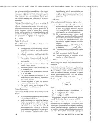
![76 NATIONAL BUILDING CODE OF INDIA 2016
out, before an installation or an addition to the existing
installation is put into service. Any testing of the
electrical installation in an already existing installation
shall commence after obtaining permit to work from
the Engineer-in-Charge and after ensuring the safety
provisions.
Testing of the installations will cover the testing of
equipment, connections, cables, switchgear, protective
devices, circuit breakers and the associated relays,
measuring instruments and earthing. Periodicity of
testing should not exceed six months. More frequent
testing may be prescribed for complex installations and
installations feeding sensitive loads. Due date of next
test cycle should be displayed on the equipment.
9.3.2 Testing
9.3.2.1 Switchboards
HV and MV switchboards shall be tested in the manner
indicated below:
a) All high voltage switchboards shall be tested
for dielectric test as per good practice
[8-2(14)].
b) All earth connections shall be checked for
continuity.
c) The operation of the protective devices shall
be tested by means of secondary or primary
injection tests.
d) The operation of the breakers shall be tested
from all control stations.
e) Indication/Signalling lamps shall be checked
for proper working.
f) The operation of the breakers shall be tested
for all interlocks.
g) The closing and opening timings of the
breakers shall be tested, wherever required for
auto-transfer schemes.
h) Contact resistance of main and isolator
contacts shall be measured.
j) The specific gravity and the voltage of the
control battery shall be measured.
9.3.2.2 Transformers
Transformers shall be tested in the manner indicated
below:
a) All commissioning tests shall be in accordance
with good practice [8-2(9)].
b) Insulation resistance on HV and MV windings
shall be measured at the end of 1 min as also
at the end of 10 min of measuring the
polarization index. The absolute value of
insulation resistance should not be the sole
criterion for determining the state of dryness
of the insulation. Polarization index values
should form the basis for determining the state
of dryness of insulation. For any class of
insulation, the polarization index should be
greater than 1.5.
9.3.2.3 Cables
Cable installations shall be checked as given below:
a) It shall be ensured that the cables conform to
the relevant Indian Standards. Tests shall also
be done in accordance with good practice
[8-2(11)]and[8-2(15)].Theinsulationresistance
before and after the tests shall be checked.
b) The insulation resistance between each
conductor and against earth shall be measured.
The insulation resistance varies with the type
of insulation used and with the length of cable.
The following empirical rule gives reasonable
guidance:
Insulation resistance =
10×Voltage, in kV
Length, in km
in megaohms
c) Physical examination of cables shall be carried
out.
d) Cable terminations shall be checked.
e) Continuity test shall be performed before
charging the cable with current.
9.3.2.4 Motors and other equipment
The following tests shall be made on motor and other
equipment.
The insulation resistance of each phase winding against
the frame and between the windings shall be measured.
Megger of 500 V or 1 000 V rating shall be used. Star
points should be disconnected. Minimum acceptable
value of the insulation resistance varies with the rated
power and the rated voltage of the motor.
The following relation may serve as a reasonable guide:
n
I
20
1000 2
E
R
P
×
=
+
where
RI = insulation resistance in mega-ohms at 25°C.
En = rated phase to phase voltage.
P = rated power, in kW.
If the resistance is measured at a temperature different
from 25°C, the value shall be corrected to 25°C.
The insulation resistance as measured at ambient
temperature does not always gives a reliable value, since
moisture may have been absorbed during shipment and
storage. When the temperature of such a motor is raised,
the insulation resistance will initially drop considerably,
even below the acceptable minimum. If any suspicion
Supplied
by
Book
Supply
Bureau
Under
the
License
from
BIS
for
LARSEN
AND
TOUBRO
CONSTRUCTION
-
MANAPAKKAM,
CHENNAI
ON
17-03-2017
09:00:59
(123.63.24.35)
valid
upto31-12-2017
ook Supply Bureau Under the License from BIS for LARSEN AND TOUBRO CONSTRUCTION - MANAPAKKAM, CHENNAI ON 17-03-2017 09:00:59 (123.63.24.35) valid up](https://image.slidesharecdn.com/india-national-building-code-nbc-2016-vol-2-220512114536-12622fb6/85/india-national-building-code-nbc-2016-vol-2-pdf-218-320.jpg)
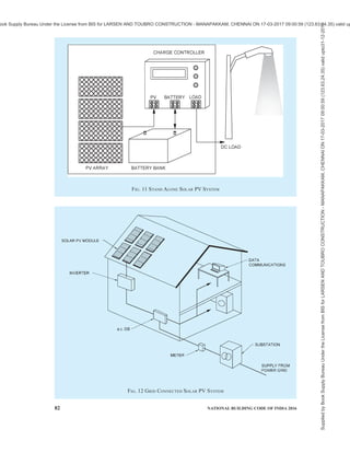
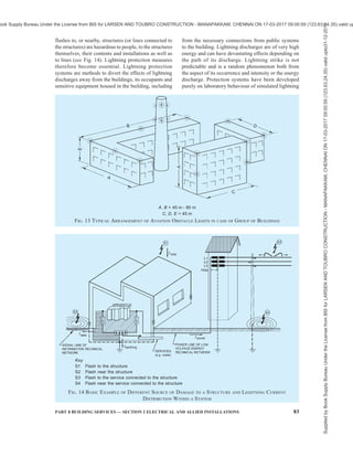

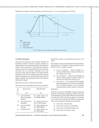
![84 NATIONAL BUILDING CODE OF INDIA 2016
strikes and methods of containing them or diverting
them to safe paths with least damage. At the same time
it is necessary to understand that lightning possibly
causes the maximum loss of life to human beings and
animals due to its unpredictability, lack of forewarning
and protection systems only provide a means of
diversion of lightning discharges to safe paths.
Lightning protection systems may be installed to avoid
accidents, severe injuries and (may be even) deaths of
humans and animals due to direct or indirect lightning.
In many cases, the need for protection may be self-
evident, for example:
a) where the area is one in which lightning
strokes are prevalent;
b) where large numbers of people congregate,
such as, sports, cultural, assembly buildings;
c) where there are very tall, complex or isolated
structures;
d) where there are structures of historic or
cultural importance;
e) structures with inherent explosive risks; for
example, explosives factories, stores and
dumps and fuel tanks;
f) where essential public services are concerned
(as lightning may lead to power outages and
unplanned interruptions of production
processes); and
g) where there is wide use of electrical and
electronic equipment/ components that are
sensitive to the effects of lightning (in industry,
ICT enabled buildings, transportation and
communication).
11.2 The maximum values of lightning current
parameters for the different lightning protection levels
(LPL) are given below and are used to design lightning
protection components (for example, cross-section of
conductors, thickness of metal sheets, current capability
of SPDs, separation distance against dangerous
sparking) and to define test parameters simulating the
effects of lightning on such components {see good
practice [8-2(46)] for details}:
First positive impulse LPL
Current parameters Symbol Unit I II III IV
Peak current I kA 200 150 100
Impulse charge QShort C 100 75 50
Specific energy W/R MJ/? 10 5.6 2.5
Time parameters T1/T2 µs/µs 10/350
First negative impulse 1)
LPL
Current parameters Symbol Unit I II III
Peak current I kA 100 75 50
Average steepness dl/dt kA/µs 100 75 50
Time parameters T1/T2 µs/µs 1/200
1)
The use of this current shape concerns only calculations and not testing.
Subsequent impulse LPL
Current parameters Symbol Unit I II III IV
Peak current I kA 50 37.5 25
Average steepness dl/dt kA/µs 200 150 100
Time parameters T1/T2 µs/µs 0.25/100
Long stroke LPL
Current parameters Symbol Unit I II III IV
Long stroke charge QLong C 200 150 100
Time parameter TLong s 0.5
Flash LPL
Current parameters Symbol Unit I II III IV
Flash charge QFlash C 300 225 150
Supplied
by
Book
Supply
Bureau
Under
the
License
from
BIS
for
LARSEN
AND
TOUBRO
CONSTRUCTION
-
MANAPAKKAM,
CHENNAI
ON
17-03-2017
09:00:59
(123.63.24.35)
valid
upto31-12-2017
ook Supply Bureau Under the License from BIS for LARSEN AND TOUBRO CONSTRUCTION - MANAPAKKAM, CHENNAI ON 17-03-2017 09:00:59 (123.63.24.35) valid up](https://image.slidesharecdn.com/india-national-building-code-nbc-2016-vol-2-220512114536-12622fb6/85/india-national-building-code-nbc-2016-vol-2-pdf-226-320.jpg)
![PART 8 BUILDING SERVICES — SECTION 2 ELECTRICAL AND ALLIED INSTALLATIONS 85
Definitions of impulse current parameters are shown in Fig. 15 {see also good practice [8-2(46)]}.
FIG. 15 DEFINITIONS OF IMPULSE CURRENT PARAMETERS
Key
O1 Virtual origin
l Peak current
T1 Front time
T2 Time to half value
11.3 Risk Assessment
The need for protection, the economic benefits of
installing protection measures and the selection of
adequate protection measures should be determined in
terms of risk assessment. The protection measures
should ensure that the calculated risk is less than the
tolerable risk (see 11.3.3). Tolerable risk is the
maximum value of the risk which can be tolerated. Risk
assessment and level of lighting protection required
shall be assessed as per the procedure laid down in
11.3.1 to 11.3.4. The good practice [8-2(47)] shall be
followed for details.
11.3.1 Typical Values of Tolerable Risk (RT)
The typical values of tolerable risk (RT) are given below:
Sl
No.
Type of Loss Tolerable Risk
(1) (2) (3)
i) Loss of human
life or permanent
injuries
10–5
(One injury out
of 100 000 strikes)
ii) Loss of service to
the public
10–3
(One service loss
out of 1 000 strikes)
iii) Loss of cultural
heritage
10–4
(One damage out
of 10 000 strikes)
iv) Economic Loss 10–3
(One failure out
of 1 000 strikes)
11.3.2 Risk Analysis and Lightning Protection Level
(LPL)
Risk analysis is done considering the following factors
and protection is divided in to four protection levels
(LPL I to IV) (see Tables 4 and 5):
a) Source of damage — Such as flashes to a
structure, flashes near a structure, flashes to a
line, flashes near a line;
b) Type of damage — Injury to living beings by
electric shock, physical damage, failure of
electrical and electronic systems; and
c) Type of loss — Loss of human life (including
permanent injury), loss of service to the public,
loss of cultural heritage, loss of economic
value (structure, content, and loss of activity).
11.3.3 Risk
Risk (R) is the value of probable average annual loss
(humans or goods) due to lightning, relative to the total
value (humans or goods) of the structure to be protected.
For each type of loss which may appear in a structure
or in a service, the relevant risk shall be evaluated for
each source and type of damage as given below:
R1 : risk of loss of human life;
R2 : risk of loss of service to the public;
R3 : risk of loss of cultural heritage; and
R4 : risk of loss of economic value.
Supplied
by
Book
Supply
Bureau
Under
the
License
from
BIS
for
LARSEN
AND
TOUBRO
CONSTRUCTION
-
MANAPAKKAM,
CHENNAI
ON
17-03-2017
09:00:59
(123.63.24.35)
valid
upto31-12-2017
ook Supply Bureau Under the License from BIS for LARSEN AND TOUBRO CONSTRUCTION - MANAPAKKAM, CHENNAI ON 17-03-2017 09:00:59 (123.63.24.35) valid up](https://image.slidesharecdn.com/india-national-building-code-nbc-2016-vol-2-220512114536-12622fb6/85/india-national-building-code-nbc-2016-vol-2-pdf-227-320.jpg)
![86 NATIONAL BUILDING CODE OF INDIA 2016
Each risk component, Rx = Nx × Px × Lx
where
Nx = number of dangerous events per annum;
Px = probability of damage to a structure; and
Lx = consequent loss.
NOTE — For annual number of thunderstorm days of various
places, 11.8 shall be referred to.
Total risk, R is the sum of various risk components. If
R RT, lightning protection is not necessary, where RT
is the tolerable risk.
Besides the need of lightning protection for a structure
or for a service, it may be useful to ascertain the
economic benefits of installing protection measures in
order to reduce the economic loss, L4. The assessment
of components of risk R4 for a structure allows the user
to evaluate the cost of the economic loss with and
without the adopted protection measures.
11.3.4 Lightning Protection Level (LPL)
Based on the risk assessment if protection is necessary,
lightning protection is divided into four levels (LPL I
to IV) which helps in designing and implementing
protection measures for an economical implementation.
LPL I provides the maximum protection and is
expensive, whereas, LPL IV provides the least
protection and is less expensive. Recommended
lightning protection level (LPL) for typical buildings
is given in Table 5 for guidance.
Complete system for protection of structures against
lightning, including their internal systems and contents,
as well as persons, in general consisting of an LPS and
SPM shall be installed to avoid damages to structures,
accidents, severe injuries and (may be even) deaths of
humans due to direct or indirect lightning. Both
protection measures should complement each other.
Before proceeding with the detailed design of a
lightning protection, the following essential steps
should be taken:
a) Decide whether or not the structure needs
protection and, if so, what are the special
requirements by making all calculations
{see good practice [8-2(47)]}.
b) Ensure a close liaison between the architect/
engineer, the builder, the lightning protective
system engineer, and the appropriate
Structure Service
(Metal Lines such as Power,
Telephone, etc)
Sl
No.
Point of
Strike
Source of
Damage
Type of Damage Type of Loss Type of Damage Type of Loss
(1) (2) (3) (4) (5) (6) (7)
D1 L1, L42)
D2 L1, L2, L3, L4 D2 L`2, L`4
1) S1
D3 L11)
, L2, L4 D3 L`2, L`4
2) S2 D3 L11)
, L2 , L4
D1 L1, L42)
D2 L1, L2, L3, L4 D2 L`2, L`4
3) S3
D3 L11)
, L2, L4 D3 L`2, L`4
4) S4 D3 L11)
, L2, L4 D3 L`2, L`4
1)
Only for structures with risk of explosion, and for hospitals or other structures where failures of internal systems immediately
endangers human life.
2)
Only for properties where animals may be lost.
Table 4 Source and Type of Damage and Type of Loss
(Clause 11.3.2)
Supplied
by
Book
Supply
Bureau
Under
the
License
from
BIS
for
LARSEN
AND
TOUBRO
CONSTRUCTION
-
MANAPAKKAM,
CHENNAI
ON
17-03-2017
09:00:59
(123.63.24.35)
valid
upto31-12-2017
ook Supply Bureau Under the License from BIS for LARSEN AND TOUBRO CONSTRUCTION - MANAPAKKAM, CHENNAI ON 17-03-2017 09:00:59 (123.63.24.35) valid up](https://image.slidesharecdn.com/india-national-building-code-nbc-2016-vol-2-220512114536-12622fb6/85/india-national-building-code-nbc-2016-vol-2-pdf-228-320.jpg)
![PART 8 BUILDING SERVICES — SECTION 2 ELECTRICAL AND ALLIED INSTALLATIONS 87
authorities throughout the design stages
(see also Note).
c) Agree the procedures for testing and future
maintenance {see good practice [8-2(47)]}.
NOTE — Modern buildings with electronic
equipment need protection from radiated surges of
lightning. To achieve this, structural steel of the
building is also sometimes used as a part of lightning
protection system {see good practice [8-2(47)]}. In
such cases, lightning protection measures shall be
included in the structural drawing, particularly for
foundation.
Table 5 Recommended LPL for Typical Buildings
(Clause 11.3.4)
Sl
No.
Application LPL
(1) (2) (3)
i) Computer data centres, military
applications, high rise hotels/hospitals,
nuclear power stations, airports,
essential services such as telecom
I
ii) Low rise hospitals/hotels, ex-zones in
the industry and chemical sector, fuel
retail outlets/gas stations/compressor
stations and similar installations
II
iii) Schools, banks, residential buildings,
temples, churches, mosques,
community halls, etc
III/IV
NOTE — Detailed risk assessment should be done before
execution.
11.4 Lightning Protection
11.5 Lightning Protection System (LPS)
The main and most effective measure for protection of
structures against physical damage is considered to be
the lightning protection system (LPS). It usually
consists of both external and internal lightning
protection systems.
An external LPS which consists of air-termination
system,down-conductorsystemandearthingsystem{see
good practice [8-2(45)] for details} is intended to,
a) intercept a lightning flash to the structure (with
an air-termination system),
b) conduct the lightning current safely towards
earth (using a down-conductor system), and
c) disperse the lightning current into the earth
(using an earth-termination system).
An internal LPS comprises equipotential bonding or a
separation distance (and hence electrical insulation)
between the external LPS components and other
electrically conducting elements internal to the
structure.
Both external and internal protection systems should
complement each other. Class of LPS denotes the
classification of an LPS according to the lightning
protection level for which it is designed. Four classes
of LPS (I, II, III and IV) are defined as a set of
construction rules, based on the corresponding LPL.
Each set includes level-dependent (for example, rolling
sphere radius, mesh width etc.) and level-independent
(for example, cross-sections, materials, etc)
construction rules {see good practice [8-2(47)]}.
Main protection measures against injury to living beings
due to touch and step voltages are intended to,
1) reduce the dangerous current flowing through
bodies by insulating exposed conductive parts,
and/or by increasing the surface soil
resistivity; and
2) reduce the occurrence of dangerous touch and
step voltages by physical restrictions and/or
warning notices.
The type and location of an LPS should be carefully
considered in the initial design of a new structure,
thereby enabling maximum advantage to be taken of
the electrically conductive parts of the structure. By
doing so, design and construction of an integrated
installation is made easier, the overall aesthetic aspects
can be improved, and the effectiveness of the LPS can
be increased at minimum cost and effort.
Access to the ground and the proper use of foundation
steelwork for the purpose of forming an effective earth-
termination may well be impossible once construction
work on a site has commenced. Therefore, soil
resistivity and the nature of the earth should be
considered at the earliest possible stage of a project.
This information is fundamental to the design of an
earth-termination system and may influence the
foundation design work for the structure.
Regular consultation between LPS designers and
installers, architects/civil engineer and builders is
essential in order to achieve the best result at minimum
cost. If lightning protection is to be added to an existing
structure, every effort should be made to ensure that it
conforms to the principles of this Code. The design of
the type and location of an LPS should take into account
the features of the existing structure.
11.5.1 Air-Termination System
11.5.1.1 Air-termination system is a part of an external
LPS using metallic elements such as rods, mesh
conductors or catenary wires intended to intercept
lightning flashes. The probability of penetration by a
lightning current on a structure is considerably
decreased by the presence of a properly designed air-
termination system. Air-termination systems can be
composed of any combination of the following
elements:
Supplied
by
Book
Supply
Bureau
Under
the
License
from
BIS
for
LARSEN
AND
TOUBRO
CONSTRUCTION
-
MANAPAKKAM,
CHENNAI
ON
17-03-2017
09:00:59
(123.63.24.35)
valid
upto31-12-2017
ook Supply Bureau Under the License from BIS for LARSEN AND TOUBRO CONSTRUCTION - MANAPAKKAM, CHENNAI ON 17-03-2017 09:00:59 (123.63.24.35) valid up](https://image.slidesharecdn.com/india-national-building-code-nbc-2016-vol-2-220512114536-12622fb6/85/india-national-building-code-nbc-2016-vol-2-pdf-229-320.jpg)
![88 NATIONAL BUILDING CODE OF INDIA 2016
a) Vertical rods (offers certain angle of
protection);
b) Catenary wires; and
c) Meshed/Grid conductors.
All types of air-termination systems shall be positioned
in accordance with 11.5.1.2. The individual air-
terminations rods should be connected together at roof
level to ensure current division. Radioactive air-
terminals shall not be allowed. Any other kind of air-
terminal like dissipation system/ESE air-terminal/CSE
air-terminal shall not be acceptable.
11.5.1.2 Positioning
Air-termination components installed on a structure
shall be located at corners, exposed points and edges
(especially on the upper level of any facades) in
accordance with one or more of the following methods
{see also Figs. 16 to 20 in conjunction with good
practice [8-2(45)]}:
a) Protection angle method;
b) Rolling sphere method; and
c) Mesh method.
The protection angle method is suitable for simple
shaped buildings but it is subject to limits of air-
termination height indicated in Table 6. The mesh
method is a suitable form of protection where plane/
pitch roof surfaces are to be protected. The rolling
sphere method is suitable in all cases. See good practice
[8-2(45)] for details.
11.5.1.3 Roof mounted electrical/electronic equipment
(for example, chillers, antennas, cameras and bill boards)
need vertical air-termination to avoid direct flashover. All
parts of lightning protection should maintain separation
distancefromtheseelectrical/electronicequipment.Power
anddataconnectiontotheseequipmentshouldhaveproper
Class I and Class II SPD’s (see 11.6.5) to avoid failures.
OverheadcablessuchascableTVlinesfromonebuilding
to the other should be avoided.
11.5.1.4 Unearthed metallic roofs should be avoided.
Metallic roofs shall be connected either to steel
reinforcement or to other earthed steel parts of the
building satisfying the requirements of number of down-
conductors (see 11.5.2). Small buildings with metallic
roofs less than 100 m2
shall be earthed at least not less
than 2 places.
11.5.1.5 Structures of height less than 60 m and more
than 60 m
On structures lower than 60 m in height, generally
flashes to the side may not occur, hence air-termination
protection on sides will not be required (see Fig. 21A).
On structures taller than 60 m, flashes to the side may
occur, especially to points, corners and edges of
surfaces. In general, the risk due to these flashes is low,
but electrical and electronic equipment on walls or
outside structures may be destroyed even by lightning
flashes with low current peak values.
An air-termination system shall be installed to protect
the upper part of tall structures (that is, typically the
topmost 20 percent of the height of the structure as far
as this part exceeds 60 m in height) and the equipment
installed on it. The rules for positioning the air-
termination systems on these upper parts of a structure
shall meet at least the requirements for LPL IV with
emphasis on the location of air-termination devices on
corners, edges, and significant protrusions (such as
balconies, viewing platforms, etc (see Fig. 21B).
11.5.1.6 Buildings with roof top solar PV and water
heaters
Vertical air-terminals are required for protecting roof
mounted installations such as solar PV, water heaters,
chillers as well as water tanks. Protection angle should
be considered as per Table 6. Vertical air-terminals need
to be connected to the air-termination mesh/down-
conductors. Metal support structure of these
installations shall be bonded to the air-termination
mesh/down-conductors. Class I/Class II surge
protection devices (SPDs) (see 11.6.5) should be
installed in the electrical lines to protect the installations
inside the building (typically d.c. SPD for solar PV
output at inverter or junction box level and a.c. SPD
Table 6 Maximum Values of Mesh Size and Protection Angle Corresponding to the Class of LPS
(Clause 11.5.1.2)
Protection Angle with respect to Height
Mesh Size Rolling Sphere
Radius
r 10 m 20 m 30 m 45 m 60 m
Sl
No.
Class of LPS
m m
(1) (2) (3) (4) (5) (6) (7) (8) (9)
i) I 5 × 5 20 45 23 Cannot be used
ii) II 10 × 10 30 54 38 23 Cannot be used
iii) III 15 × 15 45 62 48 36 3 Cannot be used
iv) IV 20 × 20 60 65 54 45 34 23
Supplied
by
Book
Supply
Bureau
Under
the
License
from
BIS
for
LARSEN
AND
TOUBRO
CONSTRUCTION
-
MANAPAKKAM,
CHENNAI
ON
17-03-2017
09:00:59
(123.63.24.35)
valid
upto31-12-2017
ook Supply Bureau Under the License from BIS for LARSEN AND TOUBRO CONSTRUCTION - MANAPAKKAM, CHENNAI ON 17-03-2017 09:00:59 (123.63.24.35) valid up](https://image.slidesharecdn.com/india-national-building-code-nbc-2016-vol-2-220512114536-12622fb6/85/india-national-building-code-nbc-2016-vol-2-pdf-230-320.jpg)

![90 NATIONAL BUILDING CODE OF INDIA 2016
NOTE — The rolling sphere, r should comply with the selected class of LPS (see Table 6).
FIG. 18 DESIGN OF AIR-TERMINATION SYSTEM ACCORDING TO THE ROLLING SPHERE METHOD
Key
1 Shaded areas are exposed to lightning interception and need protection according to Table 6
2 Mast on the structure
r Radius of rolling sphere according to Table 6
NOTE — Protection against side flashes is required {see good practice [8-2(45)] for details}.
FIG. 19 DESIGN OF AIR-TERMINATION CONDUCTOR NETWORK FOR A STRUCTURE WITH COMPLICATED SHAPE
Supplied
by
Book
Supply
Bureau
Under
the
License
from
BIS
for
LARSEN
AND
TOUBRO
CONSTRUCTION
-
MANAPAKKAM,
CHENNAI
ON
17-03-2017
09:00:59
(123.63.24.35)
valid
upto31-12-2017
ook Supply Bureau Under the License from BIS for LARSEN AND TOUBRO CONSTRUCTION - MANAPAKKAM, CHENNAI ON 17-03-2017 09:00:59 (123.63.24.35) valid up](https://image.slidesharecdn.com/india-national-building-code-nbc-2016-vol-2-220512114536-12622fb6/85/india-national-building-code-nbc-2016-vol-2-pdf-232-320.jpg)
![94 NATIONAL BUILDING CODE OF INDIA 2016
on the tower itself, special cable with increased
dielectric strength as down-conductor should be used.
Since these down-conductors are shielded, the area of
cross-section will be significantly lower than 50 mm2
but not less than 16 mm2
, which is sufficient enough to
discharge the lightning current.
Every power, coaxial, data and other metallic lines
connected between the telecom installation and the
other parts of the building shall be protected with
Class 1 and Class 2 SPD. It should be ensured that SPDs
during their operation do not impede fire safety.
11.5.1.9 Lightning protection for multi-storeyed car
park roofs/helipads
Air-termination studs (see Fig. 22) may be used for
lightning protection for multi-storeyed car park roofs/
helipads. Air-termination studs used can be connected
to the reinforcement steel of a concrete roof. In the
case of roofs where a connection to the reinforcement
cannot be made, the roof conductors can be laid in the
seams of the carriageway slabs and air-termination studs
can be located at the mesh joints. The mesh width shall
not exceed the value corresponding to the protection
class given in Table 6. The persons and vehicles on
this parking area are not protected against direct
lightning.
11.5.2 Down-conductor System
Down-conductor system is a part of an external LPS
intended to conduct lightning current from the air-
termination system to the earth-termination system. In
order to reduce the probability of damage due to
lightning current flowing in the air-termination system,
the down-conductors shall be arranged in such a way
that from the point of strike to earth,
a) several parallel current paths exist;
b) the length of the current paths is kept to a
minimum; and
c) equipotential bonding to conducting parts of
the structure is performed.
11.5.2.1 Typical values of the distance between down-
conductors are given in Table 7. These values can be
used for horizontal ring conductors installed for a tall
building more than 60 m height. The minimum number
of down-conductors shall be 2 (diagonally opposite to
each other) for building with an area less than 100 m2
.
Table 7 Minimum Distance Between
Down-Conductors
(Clause 11.5.2.1)
Sl
No.
Class of LPS Distance
m
(1) (2) (3)
i) I 10
ii) II 10
iii) III 15
iv) IV 20
11.5.2.2 Down-conductors shall be installed so that, as
far as practicable, they form a direct continuation of
the air-termination conductors. It shall be installed
straight and vertical such that they provide the shortest
and most direct path to earth. The formation of sharp
bends and loops shall be avoided. Every down-
conductor should be connected to a Type B ring/
foundation earthing. Connection of down-conductor to
a Type A earthing is allowed only in case of space
constraints or existing buildings, where installation is
difficult.
11.5.2.3 While routing the down-conductors, separation
distance need to be calculated based on good practice
[8-2(45)] and maintained from live parts/services.
Key
1 Air-termination stud
2 Steel conductor connecting to several bars of the reinforcement steel
3 Steel reinforcement to concrete
FIG. 22 TYPICAL AIR-TERMINATION STUDS USED ON CAR PARK ROOFS
Supplied
by
Book
Supply
Bureau
Under
the
License
from
BIS
for
LARSEN
AND
TOUBRO
CONSTRUCTION
-
MANAPAKKAM,
CHENNAI
ON
17-03-2017
09:00:59
(123.63.24.35)
valid
upto31-12-2017
ook Supply Bureau Under the License from BIS for LARSEN AND TOUBRO CONSTRUCTION - MANAPAKKAM, CHENNAI ON 17-03-2017 09:00:59 (123.63.24.35) valid up](https://image.slidesharecdn.com/india-national-building-code-nbc-2016-vol-2-220512114536-12622fb6/85/india-national-building-code-nbc-2016-vol-2-pdf-236-320.jpg)
![PART 8 BUILDING SERVICES — SECTION 2 ELECTRICAL AND ALLIED INSTALLATIONS 95
11.5.2.4 Lateral connection of down-conductors at
ground level and every 10 m to 20 m of height as a ring
conductor as per below table is considered to be good
practice. The installation of as many down-conductors
as possible, at equal spacing around the perimeter
interconnected by ring conductors, reduces the
probability of dangerous sparking and facilitates the
protection of internal installations {see good practice
[8-2(45)]}. This condition is fulfilled in metal
framework structures and in reinforced concrete
structures in which the interconnected steel is
electrically continuous.
11.5.2.5 Routing of down-conductors (insulated or
uninsulated) through electrical and other service shafts
are not allowed as it can create fire and explosion during
lightning.
11.5.2.6 Separation distance is the distance required
between air-terminals/lightning down-conductor and
any conductive/metallic/electrical/ electronic part of a
building to avoid uncontrolled flashover. Separation
distance (S), in m should be calculated as per the
following formula:
i c
m
K K l
S
K
× ×
=
where
Ki = depends on the selected LPL (see Table 8);
Km = depends on the electrical insulation material
(see Table 9);
Kc = depends on the partial lightning current
flowing on the air-termination and the down-
conductor (see Table 10); and
l = length, in m along the air-termination and
the down-conductor from the point where the
separation distance is to be considered, to
the nearest equipotential bonding point or
the earth-termination.
11.5.2.6.1 Cable with increased dielectric strength and
tested for lightning current discharge may be used to
avoid specific separation distance to live parts of the
building {see good practice [8-2(45)]}.
11.5.2.7 The down-conductor shall be supported on
structure like column at every 1 m using suitable clamps
or connectors or exothermic welding. The clamps or
connectors or exothermic welding shall be tested for
the lightning current as per selected LPL. Reference
may be made to table given below and good practice
[8-2(45)] for supporting details:
Sl
No.
Arrangement Fixing Centres for Tape,
Stranded and Soft Drawn
Round Conductors
mm
Fixing Centres for
Round Solid
Conductors
mm
(1) (2) (3) (4)
i) Horizontal conductors on horizontal surfaces 1 000 1 000
ii) Horizontal conductors on vertical surfaces 500 1 000
iii) Vertical conductors from the ground to 20 m 1 000 1 000
iv) Vertical conductors from 20 m and thereafter 500 1 000
NOTES
1 This table does not apply to built -in type fixings, which may require special considerations.
2 Assessment of environmental conditions (that is, expected wind load) should be undertaken and fixing centres different from those
recommended may be found to be necessary.
11.5.2.8 At the structures, which cannot be punctured
for holding the down-conductors, like tin roofs, glass
structures, etc, the down-conductors should be
supported with adhesive type clamps tested for weather
durability and for withstanding lightning currents as
per selected LPL.
11.5.2.9 The wind speed shall be taken into account
while mounting the air-termination and down-conductor
system {see good practice [8-2(45)]}.
11.5.3 Earth-termination System
Earth-termination system is a part of an external LPS
which is intended to conduct and disperse lightning
current into the earth. When dealing with the dispersion
of the lightning current (high frequency behaviour) into
the ground, whilst minimizing any potentially
dangerous over-voltages, the shape and dimensions of
the earth-termination system are the important criteria.
In general, a low earthing resistance (if possible lower
than 10 ohm when measured at low frequency) is
recommended. From the viewpoint of lightning
protection, a single integrated structure earth-
termination system is preferable and is suitable for all
purposes (that is, lightning protection, power systems
and telecommunication systems).
Type A earth-termination comprising of vertical/
horizontal conductor or Type B earth-termination
comprising of ring earthing/foundation earthing shall
be used satisfying the requirements of this Code as well
as good practice [8-2(45)].
Supplied
by
Book
Supply
Bureau
Under
the
License
from
BIS
for
LARSEN
AND
TOUBRO
CONSTRUCTION
-
MANAPAKKAM,
CHENNAI
ON
17-03-2017
09:00:59
(123.63.24.35)
valid
upto31-12-2017
ook Supply Bureau Under the License from BIS for LARSEN AND TOUBRO CONSTRUCTION - MANAPAKKAM, CHENNAI ON 17-03-2017 09:00:59 (123.63.24.35) valid up](https://image.slidesharecdn.com/india-national-building-code-nbc-2016-vol-2-220512114536-12622fb6/85/india-national-building-code-nbc-2016-vol-2-pdf-237-320.jpg)
![96 NATIONAL BUILDING CODE OF INDIA 2016
electrode (or foundation earth electrode), the area
enclosed by the ring earth electrode (or foundation earth
electrode) shall be not less than the value of Type A
earthing as given in Table 11 {see also [8-2(45)]}.
11.5.3.3 In structures where only electrical systems are
provided, a Type A earthing arrangement may be used,
but a Type B earthing arrangement is preferable. In
structures with electronic systems, a Type B earthing
arrangement is recommended.
11.5.3.4 In industrial and commercial structures, the
ring earth electrode around the structure or the ring
earth electrode in the concrete at the perimeter of the
foundation, should be integrated with a meshed network
under and around the structure, having a mesh width
of typically 5 m. This greatly improves the performance
of the earth-termination system. If the basement’s
reinforced concrete floor forms a well-defined
interconnected mesh and is connected to the earth-
termination system, typically at every 5 m, the same
will also be suitable {see good practice [8-2(45)]}.
11.5.3.5 For buildings without steel reinforced
foundation (brickwork/stones) a Type B earth-
termination (ring earthing) shall be installed.
11.5.3.6 Where large numbers of people frequently
assemble in an area adjacent to the structure to be
protected, further potential control for such areas should
be provided. More ring earth electrodes should be
installed at distances of approximately 3 m from the
first and subsequent ring conductors. Ring electrodes
further from the structure should be installed more
deeply below the surface, that is, those at 4 m from the
structure at a depth of 1 m, those at 7 m from the
structure at a depth of 1.5 m and those at 10 m from the
structure at a depth of 2 m. These ring earth electrodes
should be connected to the first ring conductor by means
of radial conductors.
11.5.3.7 For buildings integrating structural steel as
down-conductor and earth-termination, earth resistivity
Table 8 Isolation of External LPS —
Approximated Values of Coefficient, Kc
(Clause 11.5.2.6)
Sl
No.
Number of Down-
conductors, n
Kc
(1) (2) (3)
i) 1
(only in case of
an isolated LPS)
1
ii) 2 0.66
iii) 3 and more 0.44
NOTE — Values of Table 8 apply for all Type B earthing
arrangements and for Type A earthing arrangements,
provided that the earth resistance of neighbouring earth
electrodes do not differ by more than a factor of 2. If the
earth resistance of single earth electrodes differ by more than
a factor of 2, Kc = 1 is to be assumed.
Table 9 Isolation of External LPS — Values of
Coefficient, Ki
(Clause 11.5.2.6)
Sl
No.
Class of LPS Ki
(1) (2) (3)
i) I 0.08
ii) II 0.06
iii) III and IV 0.04
Table 10 Isolation of External LPS — Values of
coefficient, Km
(Clause 11.5.2.6)
Sl
No.
Material Km
(1) (2) (3)
i) Air 1
ii) Concrete, bricks, wood 0.5
NOTES
1 When there are several insulating materials in series, it is a
good practice to use the lower value for Km.
2 In using other insulating materials, construction guidance
and the value of Km should be provided by the manufacturer.
11.5.3.1 Type A earthing
Length of the earth electrode depends on the soil
resistivity and class of LPS {see [8-2(45)] for details
and Table 11 for vertical earth electrode}. For Type A,
minimum number of earth electrodes should be 2.
11.5.3.2 Type B earthing
This type of arrangement comprises either a ring
conductor external to the structure to be protected, in
contact with the soil for at least 80 percent of its total
length, or a foundation earth electrode. Such earth
electrodes may also be meshed. For the ring earth
Table 11 Minimum Length of Vertical Earth
Electrode
(Clause 11.5.3.1)
Typical Length of Each Vertical Earth
Electrode Based on Soil Resistivity
m
Sl
No.
Class
of
LPS
Up to
500 W-m
1 000 W-m 2 000 W-m 3 000 W-m
(1) (2) (3) (4) (5) (6)
i) I 2.5 10 25 40
ii) II 2.5 5 15 25
iii) III 2.5 2.5 2.5 2.5
iv) IV 2.5 2.5 2.5 2.5
Supplied
by
Book
Supply
Bureau
Under
the
License
from
BIS
for
LARSEN
AND
TOUBRO
CONSTRUCTION
-
MANAPAKKAM,
CHENNAI
ON
17-03-2017
09:00:59
(123.63.24.35)
valid
upto31-12-2017
ook Supply Bureau Under the License from BIS for LARSEN AND TOUBRO CONSTRUCTION - MANAPAKKAM, CHENNAI ON 17-03-2017 09:00:59 (123.63.24.35) valid up](https://image.slidesharecdn.com/india-national-building-code-nbc-2016-vol-2-220512114536-12622fb6/85/india-national-building-code-nbc-2016-vol-2-pdf-238-320.jpg)
![PART 8 BUILDING SERVICES — SECTION 2 ELECTRICAL AND ALLIED INSTALLATIONS 97
measurements are not required. Proper drawings should
be made based on the actual installation and submitted
to authorities if necessary. See also good practice
[8-2(45)].
11.5.4 Use of Natural Components
Natural components are conductive components
installed in a building not specifically for lightning
protection which can be used to provide the function
of one or more parts of the LPS.
Natural components made of conductive materials,
which will always remain in/on the structure (for
example, interconnected steel-reinforcement, metal
framework of the structure, steel roof, metal facade,
handrails, etc) should be used as parts of an LPS such
as air-termination, down-conductor and earthing, if it
satisfies the requirement according to good practices
[8-5(44)] and [8-5(45)]. Bonding of different metallic
installations in the building should be done to avoid
dangerous potential differences which results in
flashover. This integrated method is not only
economical but does not influence or spoil the aesthetics
of the building. It also reduces the failure of electronic
equipment inside the building from radiated lightning
effects.
In case of natural down-conductors combined with
foundation earth electrodes, test joints are not required
and earth resistance measurements are not necessary
(see also 11.5.3.7)
11.5.4.1 Continuity of steelwork in reinforced concrete
structures
Steelwork within reinforced concrete structures is
considered to be electrically continuous provided that
the major part of interconnections of vertical and
horizontal bars are welded or otherwise securely
connected. Connections of vertical bars shall be welded,
clamped or overlapped a minimum of 20 times their
diameters and bound or otherwise securely connected.
For new structures, the connections between
reinforcement elements shall be specified by the
designer or installer, in cooperation with the builder
and the civil engineer. See [8-2(45)] for details.
For structures utilizing steel reinforced concrete
(including pre-cast, pre-stressed reinforced units), the
electrical continuity of the reinforcing bars shall be
determined by electrical testing between the uppermost
part and ground level (see Fig. 23). The overall
electrical resistance should not be greater than 0.2 Ω,
measured using test equipment suitable for this purpose.
If this value is not achieved, or it is not practical to
conduct such testing, the reinforcing steel shall not be
used as a natural down-conductor. In this case it is
recommended that an external down-conductor be
installed. In the case of structures of pre-cast reinforced
concrete, the electrical continuity of the reinforcing
steel shall be established between individual adjacent
pre-cast concrete units. See [8-2(45)] for details.
11.5.4.2 Bonding network
A low impedance bonding network is needed to avoid
dangerous potential differences between all equipment
inside the building. Moreover, such a bonding network
also reduces the magnetic field, thereby reduces the
radiated surges inside the building and provides more
protection for electrical/electronic equipment {see good
practice [8-5(48)]}.
This can be realized by a meshed bonding network
integrating conductive parts of the structure, or parts
of the internal systems, and by bonding metal parts or
conductive services at the boundary of each LPZ
directly or by using suitable SPDs.
The bonding network can be arranged as a three-
dimensional meshed structure with a typical mesh width
of 5 m (see Fig. 24 and Fig. 25). This requires multiple
interconnections of metal components in and on the
structure (such as concrete reinforcement, elevator rails,
cranes, metal roofs, metal facades, metal frames of
windows and doors, metal floor frames, service pipes
and cable trays). Bonding bars (for example, ring
bonding bars, several bonding bars at different levels
of the structure) and magnetic shields of the LPZ shall
be integrated in the same way.
Conductive parts (for example, cabinets, enclosures,
racks) and the protective earth conductor (PE) of the
internal systems shall be connected to the bonding
network {see good practice [8-5(48)]}.
11.5.5 Materials and Dimensions
Copper and aluminium are recommended for exposed
areas on installations required to have a long life.
Galvanized steel may be preferred for temporary
installations such as exhibition centres. Although it is
a common practice to use material in the form of strip
for horizontal air-terminations, down-conductors and
bonds, it is more convenient to use round material,
particularly as it facilitates the making of bends in any
plane. If different materials are used in an installation,
care should be taken to avoid galvanic corrosion by
the use of bi-metallic connectors. See Tables 12 to 14
for details.
11.5.6 Protection measures against injury to living
beings due to touch voltage and step voltage shall be
provided in accordance with good practice [8-2(45)].
11.5.7 Inspection of the LPS shall be done as per the
good practice [8-2(45)].
Supplied
by
Book
Supply
Bureau
Under
the
License
from
BIS
for
LARSEN
AND
TOUBRO
CONSTRUCTION
-
MANAPAKKAM,
CHENNAI
ON
17-03-2017
09:00:59
(123.63.24.35)
valid
upto31-12-2017
ook Supply Bureau Under the License from BIS for LARSEN AND TOUBRO CONSTRUCTION - MANAPAKKAM, CHENNAI ON 17-03-2017 09:00:59 (123.63.24.35) valid up](https://image.slidesharecdn.com/india-national-building-code-nbc-2016-vol-2-220512114536-12622fb6/85/india-national-building-code-nbc-2016-vol-2-pdf-239-320.jpg)
![98 NATIONAL BUILDING CODE OF INDIA 2016
Key
1 Air-termination rod
2 Horizontal air-termination conductor
3 Down-conductor
4 T-type joint
5 Cross type joint
6 Connection to steel reinforcing rods {see E-4.3.3 and E-4.3.6 of good practice [8-2(45)]}
7 Test joint
8 Type B earthing arrangement, ring electrode
9 Flat roof with roof fixtures
10 T-type joint — corrosion resistant
NOTE — The steel reinforcement of the structure should comply with available Indian Standards. All dimensions of the LPS
should comply with the selected protection level.
FIG. 23 CONSTRUCTION OF EXTERNAL LPS ON A STRUCTURE OF STEEL-REINFORCED CONCRETE USING THE
REINFORCEMENT OF THE OUTER WALLS AS NATURAL COMPONENTS
Supplied
by
Book
Supply
Bureau
Under
the
License
from
BIS
for
LARSEN
AND
TOUBRO
CONSTRUCTION
-
MANAPAKKAM,
CHENNAI
ON
17-03-2017
09:00:59
(123.63.24.35)
valid
upto31-12-2017
ook Supply Bureau Under the License from BIS for LARSEN AND TOUBRO CONSTRUCTION - MANAPAKKAM, CHENNAI ON 17-03-2017 09:00:59 (123.63.24.35) valid up](https://image.slidesharecdn.com/india-national-building-code-nbc-2016-vol-2-220512114536-12622fb6/85/india-national-building-code-nbc-2016-vol-2-pdf-240-320.jpg)
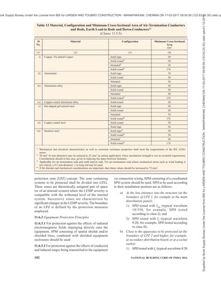
![PART 8 BUILDING SERVICES — SECTION 2 ELECTRICAL AND ALLIED INSTALLATIONS 101
Table 12 LPS Materials and Conditions of Use1)
(Clause 11.5.5)
Use Corrosion
Sl
No.
Material
In Open
Air
In Earth In
Concrete
Resistance Increased
by
May be
destroyed by
galvanic
coupling with
(1) (2) (3) (4) (5) (6) (7) (8)
Solid Solid Solid
Stranded Stranded Stranded
i) Copper
— As coating As coating
Good in many
environments
Sulphur compounds
Organic materials
—
Solid Solid Solid
ii) Hot galvanized
steel2), 3) and 4)
Stranded5)
Stranded5)
Acceptable in air, in
concrete and in benign
soil
High chlorides
content
Copper
iii) Steel with electro-
deposited copper
Solid Solid Solid Good in many
environments
Sulphur compounds
Solid Solid Solid
iv) Stainless steel
Stranded Stranded Stranded
Good in many
environments
High chlorides
content
—
Solid
v) Aluminium
Stranded
Unsuitable Unsuitable Good in atmospheres
containing low
concentrations of
sulphur and chloride
Alkaline solutions Copper
1)
This table gives general guidance only. In special circumstances more careful corrosion immunity considerations are required.
2)
Galvanized steel may be corroded in clay soil or moist soil.
3)
Galvanized steel in concrete should not extend into the soil due to possible corrosion of the steel just outside the concrete.
4)
Galvanized steel in contact with reinforcement steel in concrete may, under certain circumstances, cause damage to the concrete.
5)
Stranded conductors are more vulnerable to corrosion than solid conductors. Stranded conductors are also vulnerable where they enter
or exit earth/concrete positions. This is the reason why stranded galvanized steel is not recommended in earth.
11.6 Protection of Electrical/Electronic Systems
within Structures
11.6.1 The internal LPS shall avoid the occurrence of
dangerous sparking within the structure to be protected
due to lightning current flowing in the external LPS or
in other conductive parts of the structure. Dangerous
sparking between different parts can be avoided by
means of equipotential bonding or electrical insulation
between the parts.
Permanent failure of electrical and electronic systems
can be caused by the lightning electromagnetic impulse
(LEMP) via:
a) Conducted and induced surges transmitted to
equipment via connecting wiring; and
b) The effects of radiated electromagnetic fields
directly into equipment itself.
Surges to the structure can originate from sources
external to the structure or from within the structure
itself, and
1) surges which originate externally from the
structure are created by lightning flashes
striking incoming lines or the nearby ground,
and are transmitted to electrical and electronic
systems within the structure via these lines.
2) surges which originate internally within the
structure are created by lightning flashes
striking the structure itself or the nearby
ground. Surges can also originate internally
within the structure from switching effects (for
example, switching of inductive loads).
The coupling can arise from different mechanisms such
as,
i) resistive coupling (for example, the earth
impedance of the earth-termination system or
the cable shield resistance); and
ii) magnetic field coupling (for example, caused
by wiring loops in the electrical and electronic
system or by inductance of bonding
conductors).
In general electrical and electronic systems are subject
to damage from a lightning electromagnetic impulse
(LEMP). The wave shapes of lightning impulse and
surges are given in good practices [8-2(46)] and
[8-2(48)]. The lightning current parameters given under
11.2 may also be referred. LEMP protection measures
(SPM) need to be provided to avoid failure of internal
systems. The design of SPM should be carried out by
experts in lightning and surge protection who possesses
a broad knowledge of installation practices of lightning
protection systems.
11.6.2 Lightning Protection Zone Concept
Protection against LEMP is based on the lightning
Supplied
by
Book
Supply
Bureau
Under
the
License
from
BIS
for
LARSEN
AND
TOUBRO
CONSTRUCTION
-
MANAPAKKAM,
CHENNAI
ON
17-03-2017
09:00:59
(123.63.24.35)
valid
upto31-12-2017
ook Supply Bureau Under the License from BIS for LARSEN AND TOUBRO CONSTRUCTION - MANAPAKKAM, CHENNAI ON 17-03-2017 09:00:59 (123.63.24.35) valid up](https://image.slidesharecdn.com/india-national-building-code-nbc-2016-vol-2-220512114536-12622fb6/85/india-national-building-code-nbc-2016-vol-2-pdf-243-320.jpg)
![PART 8 BUILDING SERVICES — SECTION 2 ELECTRICAL AND ALLIED INSTALLATIONS 103
for example, SPD tested according to
class II); and
2) SPD tested with a combination wave
(typical waveform 8/20 for example, SPD
tested according to class II).
11.6.3.3 Failures of equipment due to electromagnetic
fields impinging directly onto the equipment can be
considered negligible provided the equipment complies
with the relevant radio frequency emission and
immunity (EMC) product standards. In general,
equipment is required to comply with the relevant EMC
product standards therefore SPM consisting of a
coordinated SPD system is usually considered sufficient
to protect such equipment against the effects of LEMP.
For equipment not complying with the relevant EMC
product standards, SPM consisting of a coordinated
SPD system as well as additional magnetic shielding
measures shall be considered. Coordinated SPD
protection should ensure the voltage impulses due to
conducted surges are less than the voltage impulse
withstanding capacity of the equipment as well as
shielding measures should ensure the radiated surges
are within the withstanding capacity of the equipment.
11.6.3.4 Design of SPM
SPM can be designed for protection of equipment
against surges and electromagnetic fields, as given
below. See good practice [8-2(48)] for some examples
of SPM using protection measures, such as LPS,
magnetic shields and coordinated SPD systems
(see 11.6.5).
Table 14 Material Configuration and Minimum Dimensions of Earth Electrodes1) and 2)
(Clause 11.5.5)
Minimum Dimensions
Sl
No.
Material Configuration
Earth Rod Diameter
mm
Earth Conductor
mm2
Earth Plate
mm
(1) (2) (3) (4) (5) (6)
Stranded 50
Solid round 15 50
Solid Tape 50
Pipe 20
Solid plate 500 × 500
i) Copper,
Tin plated copper
Lattice plate3)
600 × 600
Solid round 14 78
Pipe 25
Solid tape 90
Solid plate 500 × 500
Lattice plate 600 × 600
ii) Hot dipped
galvanized steel
Profile 4)
Stranded 70
Sold round 78
iii) Bare steel5)
Solid tape 75
Solid round 146)
50
iv) Copper coated steel
Solid tape 90
Solid round 15 78
v) Stainless steel7)
Solid tape 100
1)
Mechanical and electrical characteristics as well as corrosion resistance properties shall meet the requirements of IEC 62561
‘Lightning protection system components (LPSC)’ series.
2)
In case of a type B arrangement foundation earthing system, the earth electrode shall be correctly connected at least every 5 m with
the reinforcement steel.
3)
Lattice plate constructed with a minimum total length of conductor of 4.8 m.
4)
Different profiles are permitted with a cross-section of 290 mm2
and a minimum thickness of 3 mm, for example, cross profile.
5)
Shall be embedded in concrete for a minimum depth of 50 mm.
6)
250µm minimum radial copper coating, with 99.9 percent copper content
7)
Chromium 16 percent, nickel 5 percent, molybdenum 2 percent, carbon 0.08 percent.
Supplied
by
Book
Supply
Bureau
Under
the
License
from
BIS
for
LARSEN
AND
TOUBRO
CONSTRUCTION
-
MANAPAKKAM,
CHENNAI
ON
17-03-2017
09:00:59
(123.63.24.35)
valid
upto31-12-2017
ook Supply Bureau Under the License from BIS for LARSEN AND TOUBRO CONSTRUCTION - MANAPAKKAM, CHENNAI ON 17-03-2017 09:00:59 (123.63.24.35) valid up](https://image.slidesharecdn.com/india-national-building-code-nbc-2016-vol-2-220512114536-12622fb6/85/india-national-building-code-nbc-2016-vol-2-pdf-245-320.jpg)
![104 NATIONAL BUILDING CODE OF INDIA 2016
a) SPM employing spatial shields and a
coordinated SPD system will protect against
radiated magnetic fields and against conducted
surges. Cascaded spatial shields and
coordinated SPDs can reduce the magnetic field
and surges to a lower threat level.
b) SPM employing a spatial shield of LPZ 1 and
an SPD at the entry of LPZ 1 can protect
equipment against the radiated magnetic field
and against conducted surges.
NOTE — The protection would not be sufficient if the magnetic
field remains too high (due to low shielding effectiveness of
LPZ 1), or if the surge magnitude remains too high (due to a
high voltage protection level of the SPD and due to the
induction effects onto wiring downstream of the SPD).
c) SPM using shielded lines, combined with
shielded equipment enclosures, will protect
against radiated magnetic fields. The SPD at
the entry of LPZ 1 will provide protection
against conducted surges. To achieve a lower
threat level (in one step from LPZ 0 to LPZ 2),
a special SPD may be required (for example
additional coordinated stages inside) to reach
a sufficient low voltage protection level.
d) SPM using a coordinated SPD system is only
suitable to protect equipment which is
insensitive to radiated magnetic fields, since
the SPDs will only provide protection against
conducted surges. A lower threat surge level
can be achieved using coordinated SPDs.
NOTES
1 Solutions in accordance with (a) to (c) are recommended
especially for equipment which does not comply with relevant
EMC product standards.
2 An LPS in accordance with good practice [8-2(45)] that
employs only equipotential bonding SPDs provides no
effective protection against failure of sensitive electrical and
electronic systems. The LPS can be improved by reducing
the mesh dimensions and selecting suitable SPDs, so as to
make it an effective component of the SPM.
11.6.4 Equipotentialization of Services to LPS
Equipotentialization is achieved by interconnecting the
LPS with structural metal parts, metal installations,
internal systems, external conductive parts and lines
connected to the structure. See Fig. 26.
Interconnection can be done with bonding conductors,
Key
1 Power to user 2 Power meter 3 House connection box 4 Power from utility
5 Gas 6 Water 7 Central heating system 8 Electronic appliances
9 Screen of antenna cable 10 Equipotential bonding bar 11 Surge protection device 12 Isolating spark plug
M Meter
FIG. 26 EXAMPLE OF AN EQUIPOTENTIAL BONDING ARRANGEMENT
Supplied
by
Book
Supply
Bureau
Under
the
License
from
BIS
for
LARSEN
AND
TOUBRO
CONSTRUCTION
-
MANAPAKKAM,
CHENNAI
ON
17-03-2017
09:00:59
(123.63.24.35)
valid
upto31-12-2017
ook Supply Bureau Under the License from BIS for LARSEN AND TOUBRO CONSTRUCTION - MANAPAKKAM, CHENNAI ON 17-03-2017 09:00:59 (123.63.24.35) valid up](https://image.slidesharecdn.com/india-national-building-code-nbc-2016-vol-2-220512114536-12622fb6/85/india-national-building-code-nbc-2016-vol-2-pdf-246-320.jpg)
![PART 8 BUILDING SERVICES — SECTION 2 ELECTRICAL AND ALLIED INSTALLATIONS 105
where the electrical continuity is not provided by natural
bonding or by using surge protective devices (SPD’s),
where direct connections with bonding conductors is
not feasible (for example, installation of SPD’s for
power, data, telecom lines, etc). It contains at least one
non-linear component to ensure perfect equipotential
bonding. All SPD’s at the service entrance to an
installation should be able to divert 10/350 µS impulse
current depending upon selected level of protection. A
three phase four wire system should be designed for
50 percent of the Iimp of selected LPS and single phase
two wire system should be designed for 25 percent of
the Iimp of selected LPS. The lightning current
distribution for three phase four wire system is given
in Fig. 27 {see also good practice [8-2(46)]}.
11.6.5 Protection Measures with Surge Protection
Devices (SPD’s)
11.6.5.1 Lightning surges frequently cause failure of
electrical and electronic systems due to insulation
breakdown or when over voltages exceed the
equipment’s common mode insulation level. Power line
protection is fundamental, however equal importance
should be given to data, communication and
instrumentation lines of the equipment that need
protection. Equipment is protected, if its rated impulse
withstand voltage UW at its terminals is greater than
the surge overvoltage between the live conductors and
earth. If not, an SPD shall be installed.
Implementing coordinated SPD’s will provide
protection against radiated surges for equipment
{see good practice [8-2(48)]}. Shielding and routing
of power and data lines, bonding of services and various
lightning protection zones (LPZ) {see good practice
[8-2(48)]} and earthing also plays major role in
protecting electrical and electronic equipment.
SPD’s are used to protect under specified conditions,
electrical systems and equipment against various over
voltages and impulse currents such as lightning and
switching surges. SPD shall be selected according to
their environmental conditions and the acceptable
failure rates of the equipment and the SPD’s.
11.6.5.2 Failure of SPDs
Possibility of failure of any line to neutral or neutral to
earth connected SPDs should not be ruled out, hence
measures should be taken within the SPD for safe failure
or withstand in worst conditions. SPD can fail in open
or short modes. SPD should not create a fire hazard
during failure. Safe failure mode is expected from the
SPD.
11.6.5.3 Status indicators
Each SPD should have inbuilt health indicator so as to
show if protection is available. SPD should be installed
in a way that visual inspection is easily possible. Failed
SPD shall be replaced.
11.6.5.4 SPD’s for power line need to be installed
according to the type of service such as TN, TT, IT,
etc. In general, the SPDs connected as per connection
diagram given in Fig. 28 (informative) is suitable for
TT connections. Reference may be made to relevant
Indian Standard for such installations.
11.6.5.5 Selection of SPD’s
FIG. 27 BASIC EXAMPLE OF BALANCED CURRENT DISTRIBUTION
Supplied
by
Book
Supply
Bureau
Under
the
License
from
BIS
for
LARSEN
AND
TOUBRO
CONSTRUCTION
-
MANAPAKKAM,
CHENNAI
ON
17-03-2017
09:00:59
(123.63.24.35)
valid
upto31-12-2017
ook Supply Bureau Under the License from BIS for LARSEN AND TOUBRO CONSTRUCTION - MANAPAKKAM, CHENNAI ON 17-03-2017 09:00:59 (123.63.24.35) valid up](https://image.slidesharecdn.com/india-national-building-code-nbc-2016-vol-2-220512114536-12622fb6/85/india-national-building-code-nbc-2016-vol-2-pdf-247-320.jpg)
![PART 8 BUILDING SERVICES — SECTION 2 ELECTRICAL AND ALLIED INSTALLATIONS 107
SPD(s) need to be selected based on the place of
installation as well the impulse voltage withstanding
capacity of the equipment. Iimp, and In, are test parameters
used to categorize Class I and Class II SPD(s). They are
related to the maximum values of discharge currents,
which are expected to occur at the LPL probability level
at the location of installation (LPZ) of the SPD in the
system. In is associated with Class II tests and Iimp is
associated with Class I tests.
11.6.5.5.1 If no risk analysis according to good practice
[8-2(47)] has been carried out or if the current value of
SPD cannot be established, Class I SPDs should be
installed with an Iimp not less than 12.5 kA (10/350 µS)
for connection according to Fig. 28A or between L to N
or PE. For connection according to Fig. 28B, Iimp shall
not be less than 50 kA (10/350 µS) between N and PE
for three-phase systems and 25 kA (10/350 µS) between
N and PE for single-phase systems. Otherwise the
currents shall be considered as per level of protection.
11.6.5.5.2 Follow current extinguishing capability of the
SPD
Follow current is the short circuit current (rms value)
which flows through the SPD when it gets switched on
due to lightning strike or surges. The SPD has to restore
to normal condition by breaking this short circuit current
before back fuse/switchgears are stressed, in order to
retain the availability of the services by the load or to
retain the availability of protection in the network. Follow
current extinguishing capability and short circuit
withstand capacity of SPD shall be as per good practice
[8-2(48)].
11.6.5.5.3 Where Class II tested SPD {see good practice
[8-2(48)]} are required at or near the origin of
installation, the value of In shall be not less than 5 kA for
connections according to Fig. 28A or between L to N or
PE. For Class II tested SPDs connected between neutral
and PE for connection in Fig. 28B, In shall not be less
than 20 kA for three-phase systems and 10 kA for single-
phase systems.
11.6.5.5.4 Voltage protection level of SPD
The voltage protection level of SPD is the voltage that
is finally exposed to the equipment. The voltage
protection level (Up) should be less than the withstand
voltage of the equipment. The voltage protection level
of the SPD shall be as less as possible to have better
protection but it should be ensured that it should not get
switched on due to normal voltage variations or during
low spark over voltages {see good practice [8-5(48)]}.
The values of the withstand voltages of the equipment
at various supply voltages is given in Table 15.
Table 15 Rated Impulse Voltage for the Equipment Energized Directly from the Low Voltages Mains
(Clause 11.6.5.5.4)
Nominal Voltage of the Supply
System1)
Based on
IEC 60038 : 2009
‘IEC Standard Voltages’2)
Rated Impulse Voltage3)
Overvoltage Category 4)
Three Phase Single Phase
Voltage Line to
Neutral Derived
from Nominal
Voltages a.c. or d.c.
up to and Including
I II III IV
Sl
No.
V V V V V V V
(1) (2) (3) (4) (5) (6) (7) (8)
i) 50 330 500 800 1 500
ii) 100 500 800 1 500 2 500
iii) 120-240 150 800 1 500 2 500 4 000
iv) 230/400
277/480
300 1 500 2 500 4 000 6 000
v) 400/690 600 2 500 4 000 6 000 8 000
vi) 1 000 1 000 4 000 6 000 8 000 12 000
1)
See Annex B of IEC 60664-1:2007 ‘Insulation coordination for equipment within low-voltage systems — Part 1: Principles,
requirements and tests’ for application to existing different low voltage mains and their nominal voltages.
2)
The ‘/’ mark indicates a four-wire three-phase distribution system. The lower value is the voltage line-to-neutral, while the higher
value is the voltage line-to-line. Where only one value is indicated, it refers to three-wire, while the higher value is the voltage line-to-
line. Where only one value is indicated, it refers to three-wire, three-phase systems and specifies the value line-to-line.
3)
Equipment with these rated impulse voltage can be used in installations in accordance with IEC 60364-4-44 ‘Low-voltage electrical
installations — Part 4-44: Protection for safety — Protection against voltage disturbances and electromagnetic disturbances’.
4)
See 4.3.3.2.2 of IEC 60664-1:2007 ‘Insulation coordination for equipment within low-voltage systems — Part 1: Principles,
requirements and tests’ for an explanation of the overvoltage categories.
Supplied
by
Book
Supply
Bureau
Under
the
License
from
BIS
for
LARSEN
AND
TOUBRO
CONSTRUCTION
-
MANAPAKKAM,
CHENNAI
ON
17-03-2017
09:00:59
(123.63.24.35)
valid
upto31-12-2017
ook Supply Bureau Under the License from BIS for LARSEN AND TOUBRO CONSTRUCTION - MANAPAKKAM, CHENNAI ON 17-03-2017 09:00:59 (123.63.24.35) valid up](https://image.slidesharecdn.com/india-national-building-code-nbc-2016-vol-2-220512114536-12622fb6/85/india-national-building-code-nbc-2016-vol-2-pdf-249-320.jpg)
![108 NATIONAL BUILDING CODE OF INDIA 2016
11.6.5.5.5 The preferred values of voltage protection
level of SPDs, Up is given below (see IEC 61643-
11:2011):
0.08, 0.09, 0.10, 0.12, 0.15, 0.22, 0.33, 0.4, 0.5, 0.6,
0.7, 0.8, 0.9, 1.0, 1.2, 1.5, 1.8, 2.0, 2.5, 3.0, 4.0,
5.0, 6.0, 8.0 and 10 kV
Hence for protecting a 240 V/415 V connected
equipment, selecting a Up 1.5 kV will be a safer
choice. The Up may be tested and certified by a third
party as per the laid down test procedures. See Fig. 29
on connection diagram for SPD.
11.6.5.6 For small residential buildings, power line SPD
at the mains incoming panel will enhance the life of
electronic equipment, such as TV, music system,
refrigerators, LED lights, etc.
11.6.5.7 For large buildings, power line SPD is required
at incoming panel as well as for sub distribution panels
based on the LPZ principle {see good practice
[8-5(48)]}.
11.6.5.8 For industrial and commercial buildings,
critical and sensitive loads such as drives, PLC’s,
automation panels, etc require protection with SPD in
addition to SPD at incoming power panels and sub-
distribution boards. SPDs shall be selected to meet the
requirements of relevant LPZs.
11.6.5.9 Lifts, escalators, moving walks and fire panels
shall be protected with SPD in control panels. All
electrical and control panels related to safety and
security of building shall be protected with appropriate
SPDs.
11.6.5.10 SPDs should be installed for outdoor
equipment such as CCTV cameras, LED street lights,
weighbridges, firefighting systems, roof top solar PV
installations, etc. This will ensure availability of the
vital services provided by these equipment as and when
required.
11.6.5.11 Failure of equipment and chance of fire in
electrical installations are more for buildings near tall
structures (for example, telecom tower). These
buildings should be protected with SPD at power
incoming and ring earthing to avoid fire and equipment
failure.
11.6.5.12 All SPDs should have status indication to
show their healthy state for discharging the lightning
current. The possibility of failure of L-N as well as
N-PE connected SPD cannot be ignored.
11.6.5.13 The SPD shall be installed at the entrance to
ensure perfect bonding to the ground at the time of
lightning {see good practice [8-2(44)] and [8-2(48)]}.
The let through energy of the protection system shall
be less than the energy that equipment can withstand.
As per good practice [8-5(48)], the energy coordination
method is the best method to ensure the protection of
the equipment. The let through energy details of the
SPD shall be provided by manufacturer.
FIG. 29 EXAMPLE OF INSTALLATION OF SPDS AT OR NEAR ORIGIN OF INSTALLATION
Supplied
by
Book
Supply
Bureau
Under
the
License
from
BIS
for
LARSEN
AND
TOUBRO
CONSTRUCTION
-
MANAPAKKAM,
CHENNAI
ON
17-03-2017
09:00:59
(123.63.24.35)
valid
upto31-12-2017
ook Supply Bureau Under the License from BIS for LARSEN AND TOUBRO CONSTRUCTION - MANAPAKKAM, CHENNAI ON 17-03-2017 09:00:59 (123.63.24.35) valid up](https://image.slidesharecdn.com/india-national-building-code-nbc-2016-vol-2-220512114536-12622fb6/85/india-national-building-code-nbc-2016-vol-2-pdf-250-320.jpg)
![PART 8 BUILDING SERVICES — SECTION 2 ELECTRICAL AND ALLIED INSTALLATIONS 109
11.6.5.14 Maximum continuous operating voltage of
the SPD (Uc) should not be less than 1.1 × Unominal =
1.1 × 230 = 253 V; however, neutral disconnect tests
are done at much higher voltages (above 440 V) to
simulate this condition.
The Class I SPD shall be tested to withstand sustained
high voltage of minimum 460 V (L-N) under neutral
disconnect condition.
11.6.5.15 Low-voltage SPDs for connection to low-
voltage power systems shall be conforming to the
accepted standard [8-2(49)].
11.6.5.16 SPDs for data/telecommunication line shall
be selected considering following parameters:
a) Place of installation {see good practice [8-
2(48)] for lightning protection zone concept};
b) Immunity of terminal equipment;
c) Earthing of the system to be protected
(balanced/unbalanced);
d) Requirement on interface (transmission
parameters: voltage, frequency, current); and
e) Mounting interface.
These SPDs shall be tested as per Table 16.
NOTE — Reference may be made to IEC 61643-21:2000 ’Low
voltage surge protective devices — Part 21: Surge protective
devices connected to telecommunications and signalling
networks — Performance requirements and testing methods’
for requirements and test methods for SPDs for data/
telecommunication line.
Table 16 Voltage and Current Waveforms for Impulse-Limiting Voltage
(Clause 11.6.5.16)
Sl
No.
Category Type of
Test
Open-Circuit
Voltage1)
Short-Circuit
Current
Minimum Number
of Applications
Terminals to
be Tested
(1) (2) (3) (4) (5) (6) (7)
A1 Very slow
rate of rise
1 kV
Rate of rise from
0.1 kV/µs to 100 kV/s
10 A,
0.1 A/µs,
2A/ µs
1 000 µs (duration)
Not applicable
(NA)
i)
A2 AC Select a test from Table 5 of IEC 61643-21:2000
‘Low voltage surge protective devices — Part 21
surge protective devices connected to
telecommunications and signaling networks —
Performance requirements and testing methods’1)
Single cycle
B1 1 kV
10/1 000
100 A,
10/1 000
300
B2 1 kV to 4 kV
10/700
25 A to 100 A
5/300
300
ii)
B3
Slow rate of
rise
1 kV
100 V/µs
10 A to 100 A
10/1 000
300
C1 0.5 kV to 2 kV
1.2/50
0.25 kA to 1 kA 8/20 300
C2 2 kV to 10 kV
1.2/50
1 kA to 5 kA
8/20
10
iii)
C3
Fast rate of
rise
1 kV
1 kV/µs
10 A to 100 A
10/1 000
300
D1 1 kV 0.5 kA to 2.5 kA
10/350
2
iv)
D2
High energy
1 kV 0.6 kA to 2.0 kA
10/250
5
X1-C
X2-C
X1-X22)
NOTES
1 For the verification of Up, one of the above impulse waveform of Category C is mandatory and A, B and D are optional. Unless
otherwise specified, apply 5 positive and 5 negative pulses.
2 For impulse reset, select test from Category B, C and D. Unless otherwise specified, apply 3 positive and 3 negative pulses.
3 For impulse durability measurement, one impulse waveform of Category C is mandatory and A1, B and D are optional.
4 Values listed in this table are minimum requirements; other surge current ratings are possible and can also be found in other standards,
for example, ITU-T K series — Recommendations.
1)
An open-circuit voltage different from 1 kV may be used. However, it shall be sufficient to operate the SPD under test.
2)
X1-X2 terminals shall be tested only if it is required.
Supplied
by
Book
Supply
Bureau
Under
the
License
from
BIS
for
LARSEN
AND
TOUBRO
CONSTRUCTION
-
MANAPAKKAM,
CHENNAI
ON
17-03-2017
09:00:59
(123.63.24.35)
valid
upto31-12-2017
ook Supply Bureau Under the License from BIS for LARSEN AND TOUBRO CONSTRUCTION - MANAPAKKAM, CHENNAI ON 17-03-2017 09:00:59 (123.63.24.35) valid up](https://image.slidesharecdn.com/india-national-building-code-nbc-2016-vol-2-220512114536-12622fb6/85/india-national-building-code-nbc-2016-vol-2-pdf-251-320.jpg)
![110 NATIONAL BUILDING CODE OF INDIA 2016
11.7 Implementation of Lightning Protection Measures for Typical Buildings
Sl
No.
Type of Building Place Implementation
(1) (2) (3) (4)
Close to tall
structures/trees1)
SPD and ring earthing connected
to the power incoming
switchboard earth terminal
i) Buildings with no steel
reinforced foundation with
electricity connection (one or two
family private dwellings)
Isolated Class IV external LPS, SPD2)
and
ring earthing
Close to tall
structures/trees1)
SPD2)
and bonding of steel
reinforcement to earthing bonding
bar3)
ii) Buildings with steel reinforced
foundation with electricity
connection (one or two family
private dwellings)
Isolated Class IV external LPS connected
to reinforcement and down-
conductor5)
(max every 20 m).
SPD2)
and bonding3)
of steel
reinforcement to earthing bonding
bar
iii) Buildings with steel reinforced
foundation with electricity
connection (less than 20 m
height) [other than those covered
in (ii)]
Urban/suburban/rural
iv) Residential high rise buildings
(more than 20 m height) with
steel reinforced columns/ pillars
Urban/suburban/rural
Class IV External LPS connected
to reinforcement and down-
conductor5)
(max every 20 m).
SPD2)
and bonding3)
of steel
reinforcement to earthing bonding
bar
v) Educational buildings (school/
college/ training) for education or
recreation for not less than 20
students
Urban/suburban/rural
vi) Institutional buildings (Hospitals/
Jails)
Urban/suburban/rural
Assembly buildings (theatres/
passenger stations (rail/bus/air)/
exhibition halls/religious
buildings
Urban/suburban/rural
Recommended 6)
LPS as per 11.3.
SPD2)
and bonding of steel
reinforcement to earthing bonding
bar3)
. Additional step/touch
potential reduction measures in
pathways/play grounds
vii)
Assembly buildings (more than
5 000 people)
Railway stations/airport/hill
stations/mines
Urban/suburban/rural In addition to LPS as per good
practice [8-5(45)], [8-5(46)],
[8-5(47)] and [8-5(48)], lightning
safety areas shall be declared for
the assembly of people during
thunderstorm
viii) Offices, banks, data centers,
telephone exchanges, broad-
casting stations
Urban/suburban/rural
ix) Industrial buildings/Storage
buildings (without the risk of
combustible materials)
Urban/suburban/rural
Recommended6)
LPS as per good
practice 11.3. SPD2)
and bonding
of steel reinforcement to earthing
bonding bar3)
. Ring earthing as per
11.5.1 for the safe assembly area.
Supplied
by
Book
Supply
Bureau
Under
the
License
from
BIS
for
LARSEN
AND
TOUBRO
CONSTRUCTION
-
MANAPAKKAM,
CHENNAI
ON
17-03-2017
09:00:59
(123.63.24.35)
valid
upto31-12-2017
ook Supply Bureau Under the License from BIS for LARSEN AND TOUBRO CONSTRUCTION - MANAPAKKAM, CHENNAI ON 17-03-2017 09:00:59 (123.63.24.35) valid up](https://image.slidesharecdn.com/india-national-building-code-nbc-2016-vol-2-220512114536-12622fb6/85/india-national-building-code-nbc-2016-vol-2-pdf-252-320.jpg)
![PART 8 BUILDING SERVICES — SECTION 2 ELECTRICAL AND ALLIED INSTALLATIONS 111
11.8 Average Number of Thunderstorm Days
For the purpose of risk assessment, annual thunderstorm
days in various places are provided in the informal table
to be read along with Fig. 30.
12 ELECTRICAL INSTALLATIONS FOR
CONSTRUCTION AND DEMOLITION SITES
12.1 General
12.1.1 Electrical hazards are a major cause of serious
injury and even death in construction sites. Accidents
also cause loss of productivity and destroy the morale
of workers. The need to use electricity and electrical/
electronic equipment has been constantly increasing.
Without these gadgets productivity and quality of work
will suffer. Therefore the use of electricity and the use
of gadgets has to increase. Such increase requires a
proper electrical distribution system in the work site.
12.1.2 To ensure continuous supply of power during
the construction activity and maintain productivity, site
security, etc, the city power supply may required to be
supplemented by on-site standby power generation.
Some gadgets require continuity of power supply
without interruption, thereby requiring UPS systems.
In a typical large construction site there may be a large
temporary distribution network combined with more
than one source of electricity, which can make the
system quite complex from the safety point of view.
12.1.3 Problem may also arise in case of lack of
required training to workers in the safe use of the tools
and equipment that they are required to handle in a
system with multiple sources of power supply. In case
of use of imported equipment which may be
manufactured to their own standards, problems may
arise, such as, during connection and inter-connection
of equipment and tools and mismatch of plugs and
sockets.
12.1.4 Practical guidance to employers, designers,
manufacturers, importers, suppliers (including hirers),
electrical contractors and electricians on eliminating
or reducing the risk of electrocution and electric shock
to any person is necessary.
12.1.5 Even though awareness exists about good
practices, the same may be compromised at times in
the name of speed or economy or due to ignorance and
neglect. The materials, equipment, tools, cables,
switchgear used in the temporary installation face far
more severe environmental working conditions. Use
of discarded switchgear, cables, etc, at the construction
sites compounds the risk to workmen from shock and
fire. The laid down standard need to be followed during
construction and demolition meticulously as in the case
of permanent installations during building use.
12.2 Installation and Removal of Construction
Wiring
All construction wiring work shall be installed by an
appropriately registered electrical worker as required
by The Indian Electricity Act, 2003 and only by
Sl
No.
Type of Building Place Implementation
(1) (2) (3) (4)
x) Hazardous Buildings (storage
and handling of highly
flammable or explosive
materials, liquids or gases7)
Urban/suburban/rural
1)
Side flashes from trees/tall structures are expected if the building is within 5 m. To reduce the impact of side flash, metal conductors
(down-conductors) connected to ring earthing need to be installed near the tall structure.
2)
SPD shall be installed in all the incoming services like power, telephone, data , etc.
3)
May not be possible for an existing building. Ring earthing is recommended as an alternate. Provision to bond the steel reinforcement
to the earthing bus bar shall be provided during the construction of the building using a corrosion resistant metal ( such as stainless
steel).
4)
Direction boards towards lightning safe area shall be shown.
5)
Down-conductor can be avoided, if reinforcement steel is interconnected according to good practice [8 -5(44)].
6)
Recommended LPS — Class of LPS as derived in a ri sk assessment calculation as per 11.3.
7)
Lightning protection with insulated materials can avoid safety distance of LPS from these installations.
8)
The quality of the connectors and other components of the LPS shall be ensured by following tests:
a) Salt mist test;
b) Humid sulphurous atmosphere treatment tests;
c) Electrical tests for lightning current and resistance;
d) Mechanical strength tests – tensile strength, minimum elongation test; and
e) Metal compatibility tests.
Supplied
by
Book
Supply
Bureau
Under
the
License
from
BIS
for
LARSEN
AND
TOUBRO
CONSTRUCTION
-
MANAPAKKAM,
CHENNAI
ON
17-03-2017
09:00:59
(123.63.24.35)
valid
upto31-12-2017
ook Supply Bureau Under the License from BIS for LARSEN AND TOUBRO CONSTRUCTION - MANAPAKKAM, CHENNAI ON 17-03-2017 09:00:59 (123.63.24.35) valid up](https://image.slidesharecdn.com/india-national-building-code-nbc-2016-vol-2-220512114536-12622fb6/85/india-national-building-code-nbc-2016-vol-2-pdf-253-320.jpg)

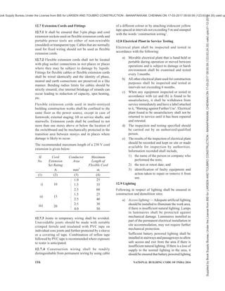
![114 NATIONAL BUILDING CODE OF INDIA 2016
electrical workmen holding licence of the appropriate
level of competence depending on the voltage, local
generation, etc. The installation should be inspected
prior to commissioning and at regular intervals by the
Engineer-in-Charge (if he is qualified to inspect
electrical installations) or by his representative, who
should be competent to inspect an installation.
12.3 Provision of Indicating and Recording
Instruments and Meters
Measurement is a prerequisite to analyze the
performance. Construction site switchboards should
have adequate instrumentation (such as, ammeters, PF
meters, voltmeters, energy meters) on different branches
of the distribution system so that any abnormal
condition or overload is noticed. Considering the nature
of varying activity in a construction site, frequent visual
and instrument based inspections are necessary keeping
record of the same.
12.4 RCCB/RCD
Following shall be ensured in construction and
demolition sites:
a) Every electric supply to which electrical plant
can be connected should incorporate an
RCCB/RCD so as to protect persons who may
come into contact with the electrical plant
against electric shock.
b) The RCCB/RCD(s) should have a rated
tripping current not exceeding 30 mA and
should have the capacity to carry the load
current required by the appliances permitted
to be connected in that branch circuit or feeder.
c) Where construction work supply can only be
obtained from a permanent wiring socket
outlet, RCCB/RCD should be connected at the
socket outlet.
d) Sub-mains supplying site sheds should
incorporate an RCCB/RCD having a rated
tripping current not exceeding 100 mA.
e) Every non-portable RCCB/RCD device on the
worksite shall be trip tested by the built-in
push button test monthly, and performance
tested for operation before being put into
service and thereafter at least once every
12 months. It shall also be subjected to an
imbalance of current not less than the rated
residual current and shall trip in a time not
exceeding 6 s.
f) Every portable RCCB/RCD device on the
worksite shall be trip tested by the built-in
push button test. The test shall be done prior
to use and each day while in use; and it shall
be performance tested for operation before
being put into service and thereafter at least
once every 3 months. It shall also be subjected
to an imbalance of current not less than the
rated residual current and shall trip in a time
not exceeding 6 s.
g) Results of RCCB/RCD tests shall be recorded
and kept on site or made available for audit
and kept for a minimum period of 5 years
[excluding the daily push button test for
portable RCCB/RCD(s)].
h) Portable RCCB/RCD(s) when tested shall be
fitted with a durable, non-reusable, non-
metallic tag. The tag shall include the
following information:
1) The name of the person or company who
performed the tests; and
2) The test or retest date.
The recommended colour coding for tags on
tested RCCB/RCD, which is prescribed below
should be indicated by its colour representing
the period when the test was performed:
January – March : Red
April – June : Green
July – September : Blue
October – December : Yellow
j) Portable generators should be fitted with
RCDs and the RCDs should be fitted with core
balance earth leakage protection having a rated
tripping current not exceeding 30 mA.
k) Personal hoists used on construction sites shall
be supplied from a separate final sub-circuit
originating from the main switchboard; and
be suitably identified by marking this supply,
the RCD/MCB feeding it.
12.5 Temporary Supply Switchboards
All temporary supply switchboards used on building,
construction and demolition sites shall be of robust
construction and either securely attached to a pole, post
wall or other structure which may be of stable
freestanding design and,
a) where installed in outdoor locations, should
be constructed and maintained to IP23 (or
higher) rating so that safe operation is not
affected by the weather;
b) switchboards should incorporate the support
and elevation of cables and flexible extension
cords;
c) switchboard enclosures shall be provided with
an insulated or covered tie-bar or similar
arrangement for the anchorage of the cables
Supplied
by
Book
Supply
Bureau
Under
the
License
from
BIS
for
LARSEN
AND
TOUBRO
CONSTRUCTION
-
MANAPAKKAM,
CHENNAI
ON
17-03-2017
09:00:59
(123.63.24.35)
valid
upto31-12-2017
ook Supply Bureau Under the License from BIS for LARSEN AND TOUBRO CONSTRUCTION - MANAPAKKAM, CHENNAI ON 17-03-2017 09:00:59 (123.63.24.35) valid up](https://image.slidesharecdn.com/india-national-building-code-nbc-2016-vol-2-220512114536-12622fb6/85/india-national-building-code-nbc-2016-vol-2-pdf-256-320.jpg)
![PART 8 BUILDING SERVICES — SECTION 2 ELECTRICAL AND ALLIED INSTALLATIONS 119
different risks, which in the absence of special
arrangements, will give rise to an increased risk of
electric shock:
1) Wetness or condensation, that is, reduced skin
resistance;
2) Absence of clothing, that is, greater
opportunity to make direct or indirect contact
through increased area of bare skin and bare
feet;
3) Proximity of earthed metalwork, that is,
increased risk of indirect contact; and
4) Arduous or onerous site conditions, that is,
conditions of use that may impair the
effectiveness of the protective measures.
13.1.3.1 The additional requirements for these ‘special
locations’ have been devised by assessing the relevant
risks under each of the above categories and making
adjustments to the protective measures accordingly. The
NOTES
1 As regards ventricular fibrillation, this figure relates to the effects of current which flows in the path ‘left hand to feet’. For other
current paths, see 5 and Table III of the accepted standard [8-2 (50)].
2 The point 500 mA/100 ms corresponds to fibrillation probability in the order of 0.14 percent.
FIG. 31 TIME/CURRENT ZONES OF THE EFFECTS OF a.c. CURRENTS (15 HZ TO 100 HZ)
mA
ms
DURATION
OF
CURRENT-FLOW,
t
Supplied
by
Book
Supply
Bureau
Under
the
License
from
BIS
for
LARSEN
AND
TOUBRO
CONSTRUCTION
-
MANAPAKKAM,
CHENNAI
ON
17-03-2017
09:00:59
(123.63.24.35)
valid
upto31-12-2017
ook Supply Bureau Under the License from BIS for LARSEN AND TOUBRO CONSTRUCTION - MANAPAKKAM, CHENNAI ON 17-03-2017 09:00:59 (123.63.24.35) valid up](https://image.slidesharecdn.com/india-national-building-code-nbc-2016-vol-2-220512114536-12622fb6/85/india-national-building-code-nbc-2016-vol-2-pdf-261-320.jpg)
![120 NATIONAL BUILDING CODE OF INDIA 2016
intention is to remove or minimize the additional risks
to users presented by the electrical installations within
these ‘special locations’. Designers, installers and
operators of such installations should consider the
particular requirements of the installation and design
and install or operate the installation to reduce or protect
against risks from these requirements. It should be
however recognized, that all installations require
adequate regular periodic inspection and testing, and
any necessary maintenance or repair works be properly
carried out.
13.2 Protection Against Electric Shocks
13.2.1 Protective measures against electric shock are
based on following two common dangers:
a) Contact with an active conductor, which is live
with respect to earth in normal circumstances;
and is referred to as a ‘direct contact’ hazard.
b) Contact with a conductive part of an apparatus
which is normally dead, but which has become
live due to insulation failure in the apparatus;
and is referred to as an ‘indirect contact’ hazard.
The third type of shock hazard exists in the
proximity of MV or LV (or mixed) earth
electrodes which are passing earth-fault
currents.
c) This hazard is due to potential gradients on the
surface of the ground and is referred to as a
‘step-voltage’ hazard; shock current enters one
foot and leaves by the other foot, and is
particularly dangerous for four-legged animals.
A variation of this danger, known as a ‘touch
voltage’ hazard can occur, for instance, when
an earthed metallic part is situated in an area in
which potential gradients exist. Touching the
part would cause current to pass through the
hand and both feet. Animals with a relatively
long front-to-hind legs span are particularly
sensitive to step-voltage hazards.
NOTE — Cattle have been killed by the potential
gradients caused by a low voltage (240/415 V) neutral
earth electrode of insufficiently low resistance.
13.2.2 Potential-gradient problems as mentioned
in 13.2.1 are not normally encountered in electrical
installations of buildings, provided that equipotential
conductors properly bond all exposed metal parts of
equipment and all extraneous metal (that is, those which
are not part of an electrical apparatus or the installation,
for example structural steelwork, etc) to the protective-
earthing conductor.
Potential-gradient problems do exist at the switchboards
of electrical installations. Even where components, such
as the metallic cubicle and operating handle are earthed,
there is a possibility that for very short duration when a
fault current is flowing through the metal part, the
potential of the earthed metal part may be increased due
to the current flow. The practice of using an insulating
mat at places where the switches are to be operated, is
for protection against such transient over-voltages in
earthed metal parts (if the metal part is not earthed the
transient overvoltage will be beyond safe limits).
With the increased use of pumped water in bathrooms
for spa-baths, power showers, etc, there is a need, on
occasions, to provide for motive power within the area
of the bath. In order to protect against direct and indirect
contact, supplies for such equipment shall be by extra-
low-voltage-system with the nominal voltage not
exceeding 12 V r.m.s.
It is a requirement to provide supplementary
equipotential bonding by bonding all simultaneously
accessible exposed and extraneous conductive parts. This
should include all in-coming metallic services (including
metal wastes) and any structural metalwork, including a
metallic floor grid, if provided.
Protection measures as given in 13.2.3 to 13.2.5 shall
also be provided for protection against electric shock.
13.2.3 Direct-Contact Protection or Basic Protection
The main form of protection against direct contact
hazards is to contain all live parts in housings of
insulating material or in metallic earthed housings, by
placing out of reach (behind insulated barriers or at the
top of poles) or by means of obstacles. Where insulated
live parts are housed in a metal envelope, for example
transformers, electric motors and many domestic
appliances, the metal envelope is connected to the
installation protective earthing system. Protection
classification and the details of the different levels of
protection are designated by IP XX and IK X {see good
practice [8-2(6)] and IEC 62262:2002 ‘Degrees of
protection provided by enclosures for electrical
equipment against external mechanical impacts (IK
code)’}. The metallic enclosure has to demonstrate an
electrical continuity, then establishing a good segregation
between inside and outside of the enclosure. Proper
grounding of the enclosure further participates to the
electrical protection of the operators under normal
operating conditions. For LV appliances this is achieved
through the third pin of a 3-pin plug and socket. Total or
even partial failure of insulation to the metal, can raise
the voltage of the envelope to a dangerous level
(depending on the ratio of the resistance of the leakage
path through the insulation, to the resistance from the
metal envelope to earth). The minimum standard for any
equipment has to be IP2X to limit the possibility of a
finger touching a live part of an electrical system.
13.2.4 Indirect-Contact Protection or Fault Protection
A person touching the metal envelope of an apparatus
with a faulty insulation is said to be making an indirect
contact. An indirect contact is characterized by the fact
that a current path to earth exists (through the protective
earthing (PE) conductor) in parallel with the shock
current through the person concerned. The hazard in such
cases is dependent on the earth resistance and the
Supplied
by
Book
Supply
Bureau
Under
the
License
from
BIS
for
LARSEN
AND
TOUBRO
CONSTRUCTION
-
MANAPAKKAM,
CHENNAI
ON
17-03-2017
09:00:59
(123.63.24.35)
valid
upto31-12-2017
ook Supply Bureau Under the License from BIS for LARSEN AND TOUBRO CONSTRUCTION - MANAPAKKAM, CHENNAI ON 17-03-2017 09:00:59 (123.63.24.35) valid up](https://image.slidesharecdn.com/india-national-building-code-nbc-2016-vol-2-220512114536-12622fb6/85/india-national-building-code-nbc-2016-vol-2-pdf-262-320.jpg)

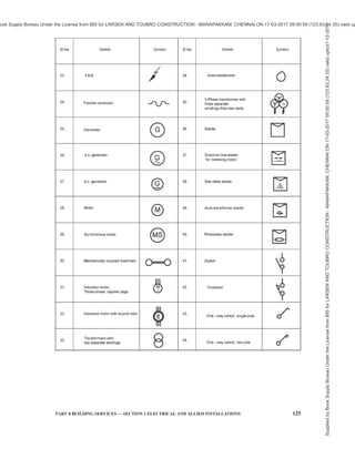
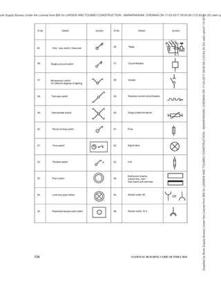
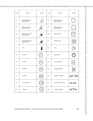
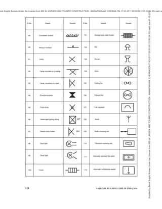
![126 NATIONAL BUILDING CODE OF INDIA 2016
SINo. Details Symbol SINo. Details Symbol
~
/
- ..
56. Relay T
45. One - way switch, three pole
N 2
46. Single pole pull switch
~ 57. Circuit-Breaker
¢
47. Multiposition switch
V 58. Isolator
~
for different degrees of lighting
I
48. Two-way switch
/ 59. Residual current circuit breaker
..f'V1../I-*-
49. Intermediate switch
X 60. Surge protective device
~
50. Period limiting switch
crf 61 . Fuse
$
51 . Time switch
l~o'O I
62. Signal lamp
®
52. Pendant switch
cfP 63. Link
~
co I I
Distribution boards,
53. Push botton 64. cubicle box, main
fuse board with switches
I I
54. Luminous push botton
C® 65. Socket outlet, 6A
YOR A
55. Restricted access push botton
@] 66. Socket outlet, 16 A
A
Supplied
by
Book
Supply
Bureau
Under
the
License
from
BIS
for
LARSEN
AND
TOUBRO
CONSTRUCTION
-
MANAPAKKAM,
CHENNAI
ON
17-03-2017
09:00:59
(123.63.24.35)
valid
upto31-12-2017
ook Supply Bureau Under the License from BIS for LARSEN AND TOUBRO CONSTRUCTION - MANAPAKKAM, CHENNAI ON 17-03-2017 09:00:59 (123.63.24.35) valid up](https://image.slidesharecdn.com/india-national-building-code-nbc-2016-vol-2-220512114536-12622fb6/85/india-national-building-code-nbc-2016-vol-2-pdf-268-320.jpg)
![PART 8 BUILDING SERVICES — SECTION 2 ELECTRICAL AND ALLIED INSTALLATIONS 129
ANNEX B
[Clauses 3.1, 4.2.1 (12) (ix), 4.7.1.2, 4.7.1.4, 4.7.1.5, 4.7.3.1, 5.3.6.8, 5.4.1.1,
5.4.1.3, 6.4.6, 8.2.1 and 9.1.1]
EXTRACTS FROM CENTRAL ELECTRICITY AUTHORITY (MEASURES RELATING TO SAFETY
AND ELECTRIC SUPPLY) REGULATION, 2010 FURTHER AMENDED IN 2015
B-1 The following are the extracts of some of the rules:
Regulation 4, Inspection of designated officers and
other safety measures
(1) The register maintained under sub-regulation
(2) of regulation 3 shall be produced before
the Electrical Inspector when required by him.
(2) If on inspection, the Electrical Inspector finds
that the designated person does not fulfill the
required qualification, he shall recommend the
removal of the name of such persons from the
register.
Regulation 5, Electrical safety officer
(1) All suppliers of electricity including
generating companies, transmission
companies and distribution companies shall
designate an Electrical Safety Officer for
ensuring observance of safety measures
specified under these regulations in their
organization, for construction, operation and
maintenance of power stations, sub-stations,
transmission and distribution lines.
(2) The Electrical Safety Officer shall be an
Electrical Engineering degree holder with at
least five years of experience in operation and
maintenance of electrical installations.
(3) The Electrical Safety Officer designated under
sub-regulation (1), shall carry out periodic
tests as per the relevant standards and
inspection of such installations for ensuring
observance of safety measures specified under
these regulations at intervals not exceeding
one year, and keep a record thereof in Form I
or Form II or Form III, as the case may be, of
Schedule IV and test reports, and also keep a
register of recommended safety requirements
duly acknowledged by the owner with date
and compliances thereafter; and such records
shall be made available to the Electrical
Inspector, as and when required.
(4) For every electrical installation including
factory registered under the Factories Act,
1948 (63 of 1948) and mines and oil field as
defined in the Mines Act, 1952 (35 of 1952),
where more than 250 kW of electrical load is
connected, the owner of the installation or the
management of the factory or mines, as the
case may be, shall designate Electrical Safety
Officer having qualification and experience
specified in sub-regulation (2), for ensuring
the observance of the safety provisions laid
under the Act and the regulations made
thereunder, who shall carry out recommended
periodic tests as per the relevant standards,
and inspect such installation at intervals not
exceeding one year, and keep a record thereof
in Form I or Form II or Form III, as the case
may be, of Schedule IV to these regulations;
test reports and a register of recommendations
in regard with safety duly acknowledged by
owner; compliances made thereafter; and such
records shall be made available to the
Electrical Inspector, as and when required.
Regulation 5A, Chartered Electrical Safety
Engineer
The Appropriate Government may authorize Electrical
Safety Engineers having the qualification and
experience as specified in sub-regulation (2) of
regulation 5 to assist the owner or supplier or consumer
of electrical installations for the purpose of self-
certification under regulation 30 and regulation 43.
Regulation 8, Keeping of records and inspection
thereof
(1) The generating company or licensee shall
maintain records of the maps, plans and
sections relating to supply or transmission of
electricity and submit the same to the
Electrical Inspector for inspection as and when
required by him.
(2) The Electrical Inspector shall supply a copy
of the report of inspection referred to in sub-
regulation (1), to the generating company or
licensee, as the case may be.
Regulation 12, General safety requirements
pertaining to construction, installation, protection,
operation and maintenance of electric supply lines
and apparatus
(1) All electric supply lines and apparatus shall
be of sufficient rating for power, insulation
and estimated fault current and of sufficient
Supplied
by
Book
Supply
Bureau
Under
the
License
from
BIS
for
LARSEN
AND
TOUBRO
CONSTRUCTION
-
MANAPAKKAM,
CHENNAI
ON
17-03-2017
09:00:59
(123.63.24.35)
valid
upto31-12-2017
ook Supply Bureau Under the License from BIS for LARSEN AND TOUBRO CONSTRUCTION - MANAPAKKAM, CHENNAI ON 17-03-2017 09:00:59 (123.63.24.35) valid up](https://image.slidesharecdn.com/india-national-building-code-nbc-2016-vol-2-220512114536-12622fb6/85/india-national-building-code-nbc-2016-vol-2-pdf-271-320.jpg)


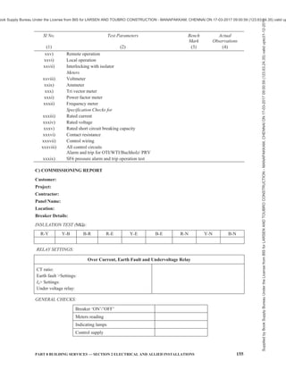
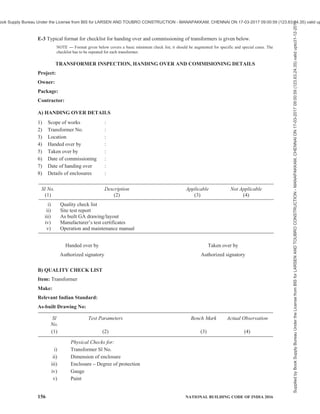
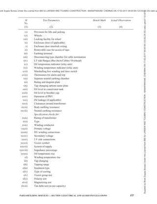
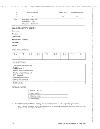
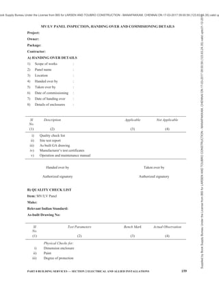
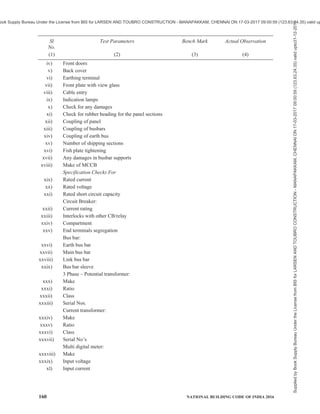
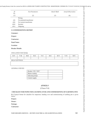
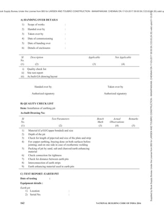
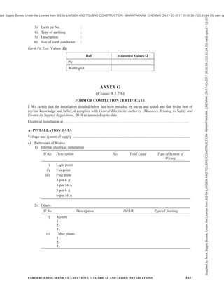
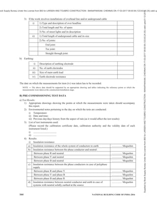
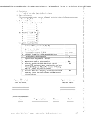
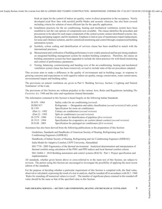


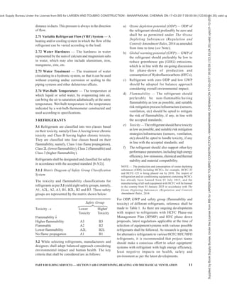


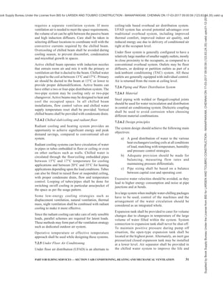
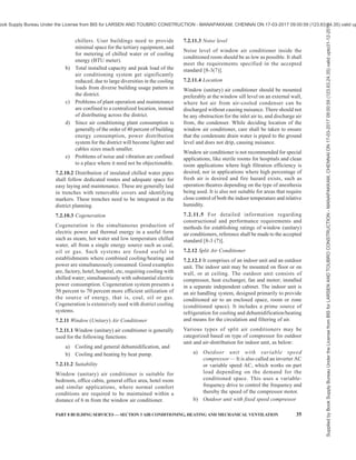
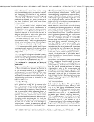
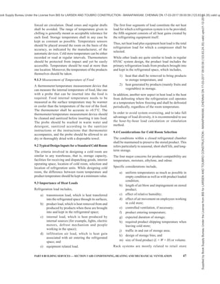

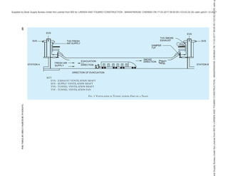


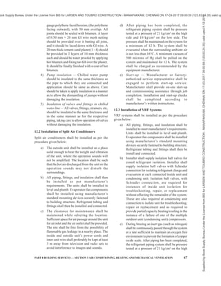
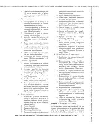

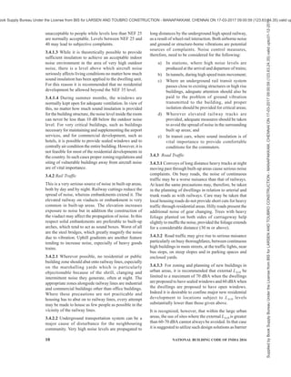

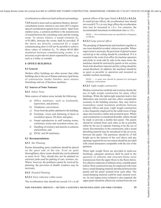

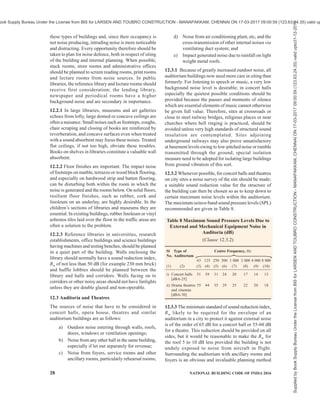
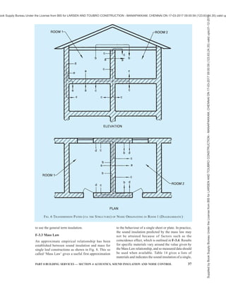

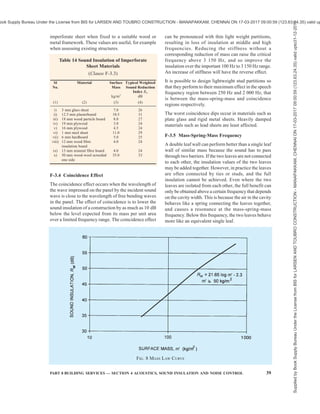


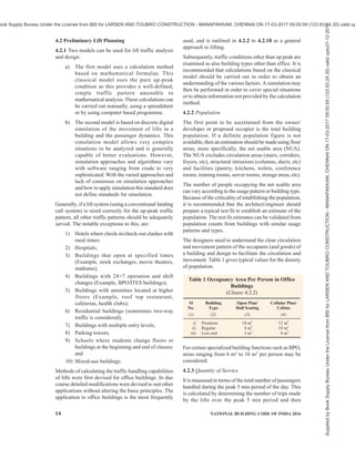

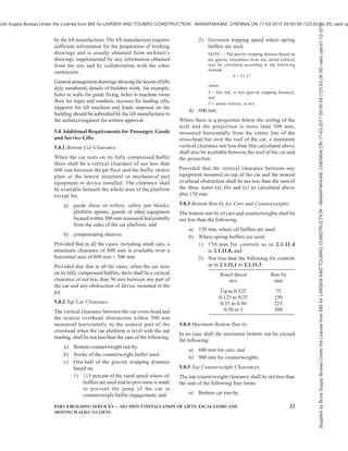

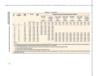
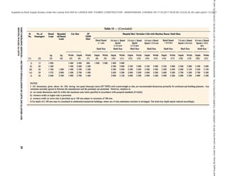
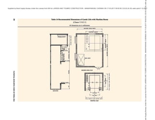
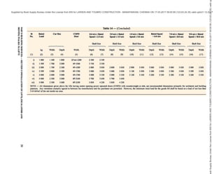
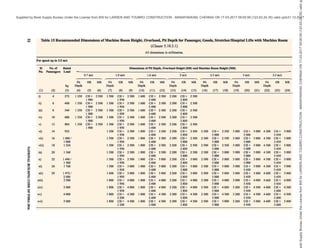
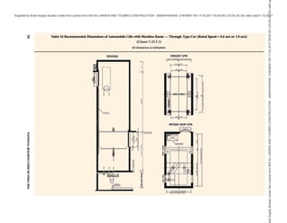
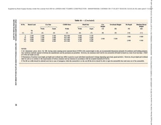
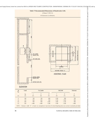

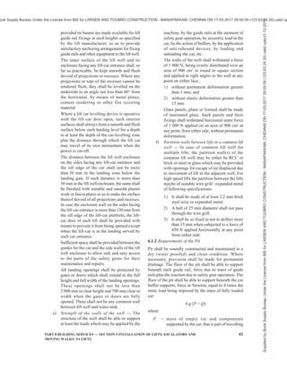
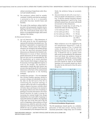
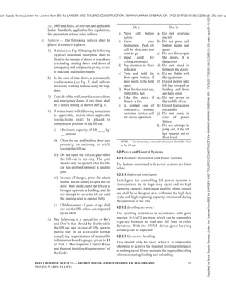
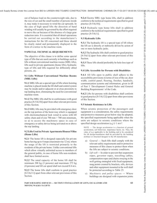
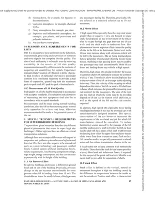


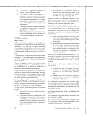
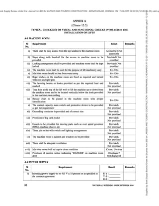
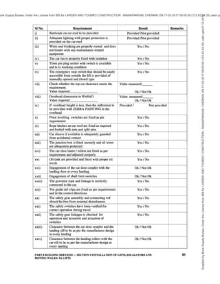
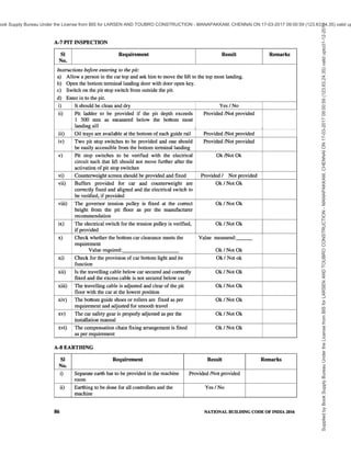
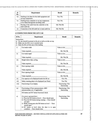
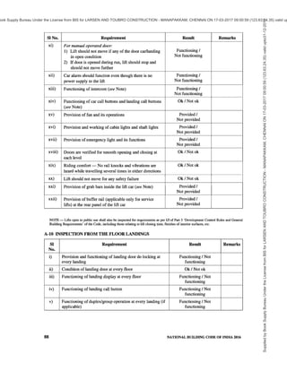
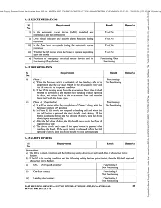
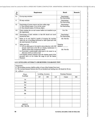
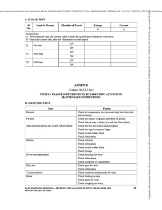
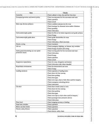
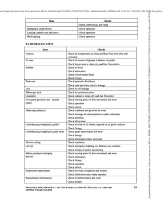
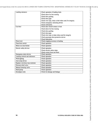
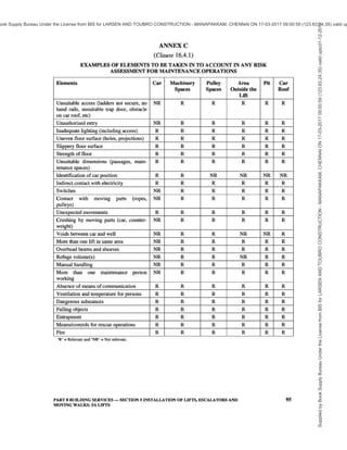


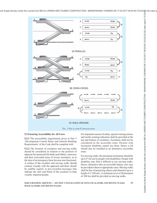


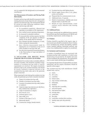
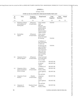
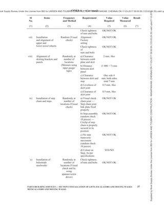
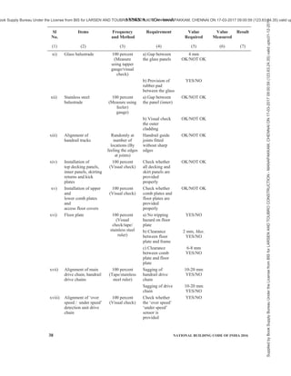
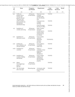

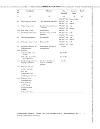
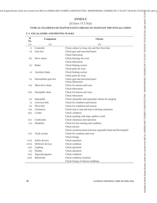
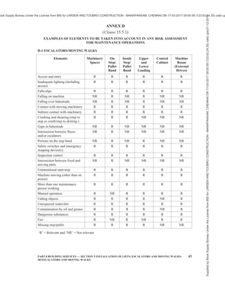


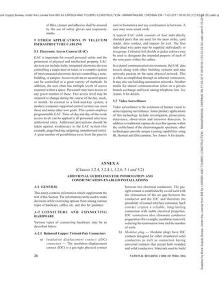

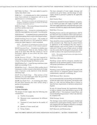
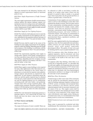
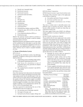
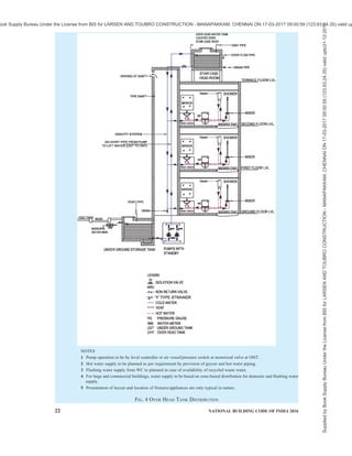
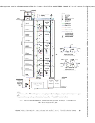
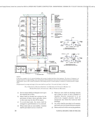
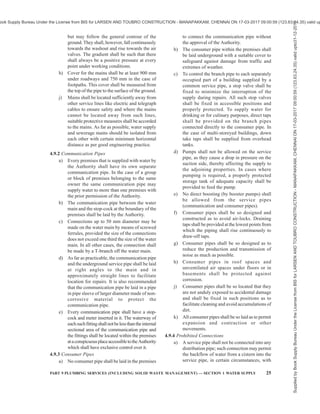
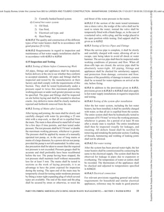


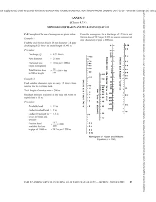

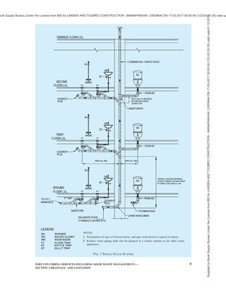
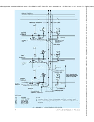
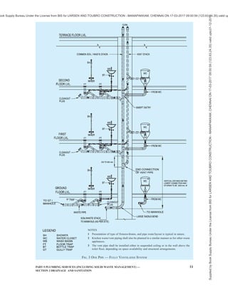
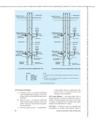
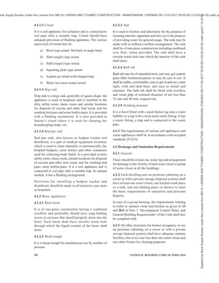

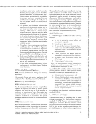


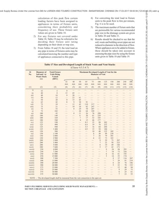
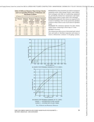

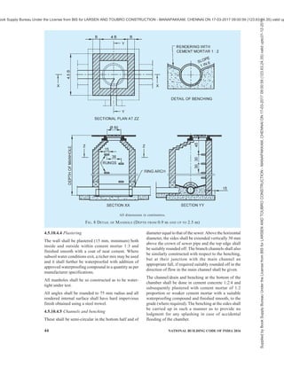


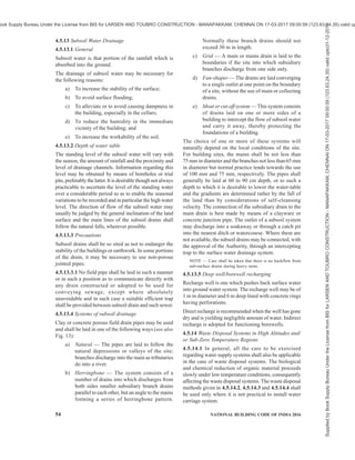
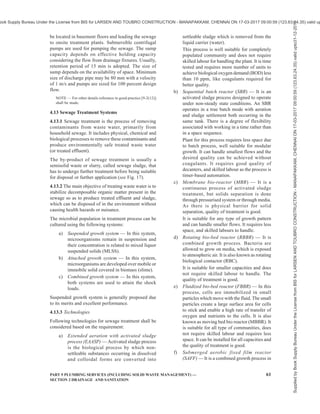
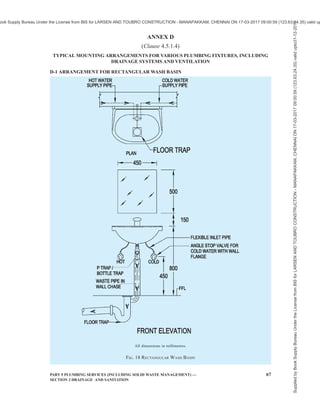
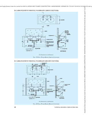
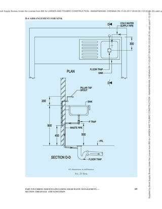
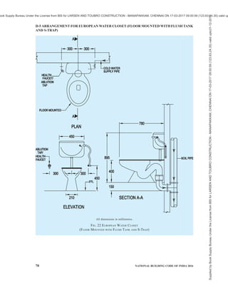
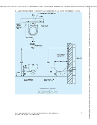
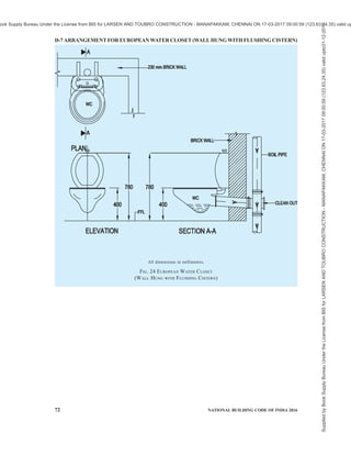
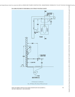
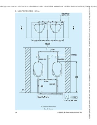
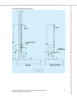
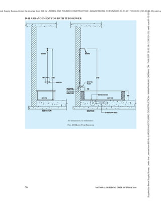
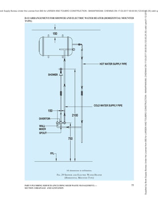
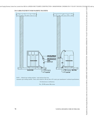

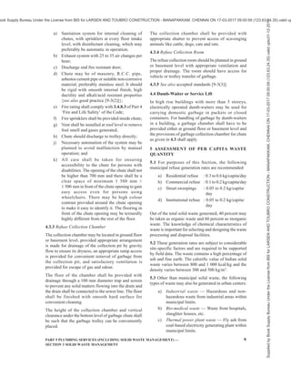


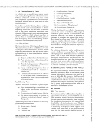

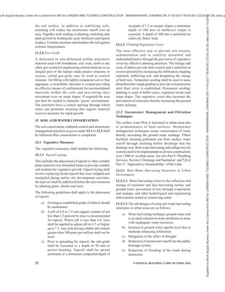

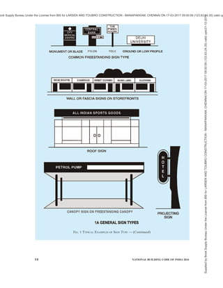
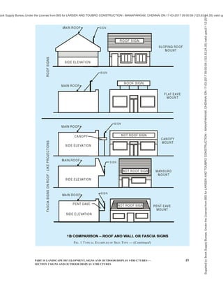


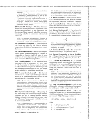
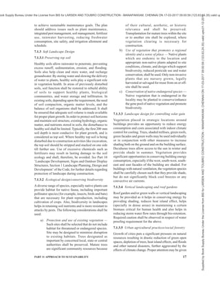
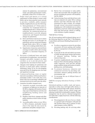

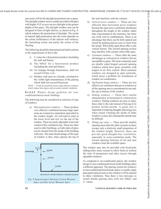
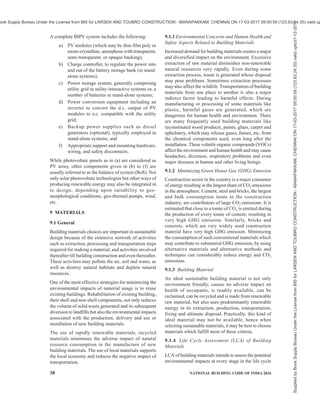
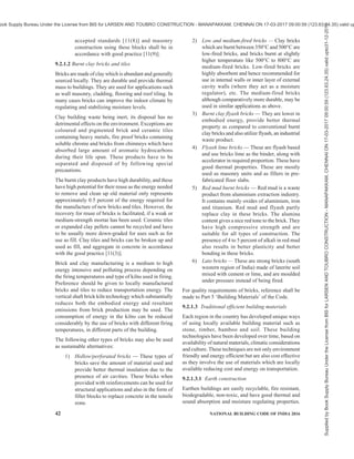
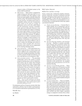
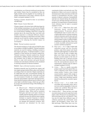


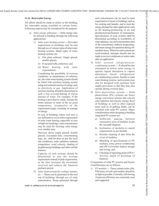
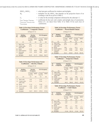


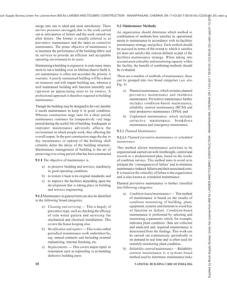
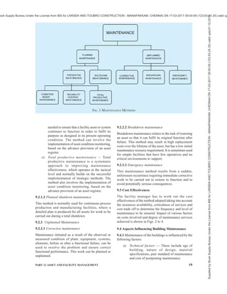
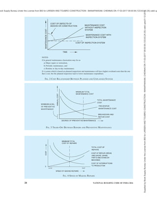

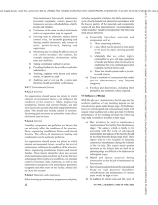
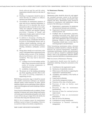

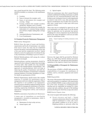
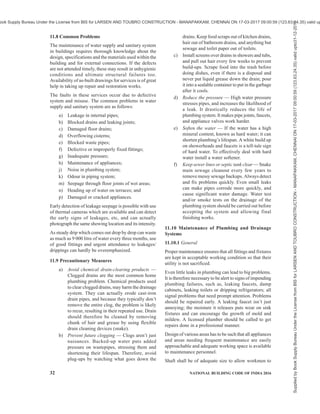


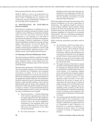

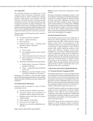


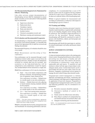


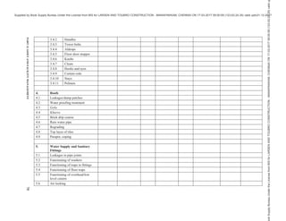
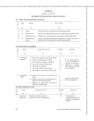
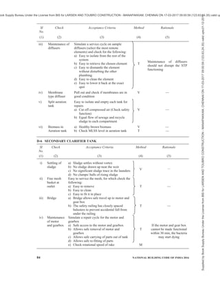
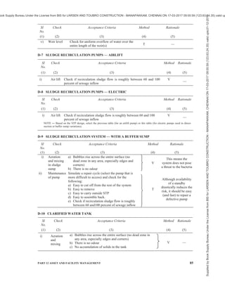

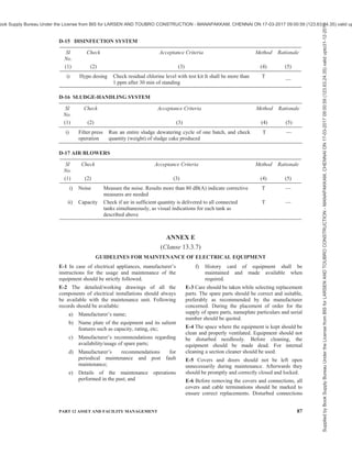

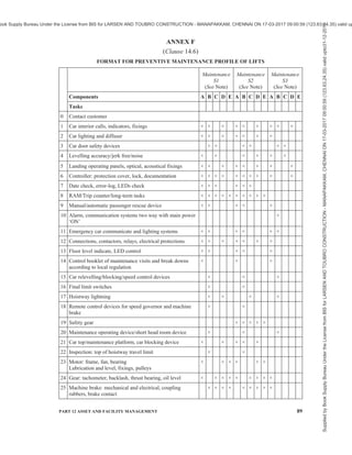


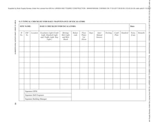
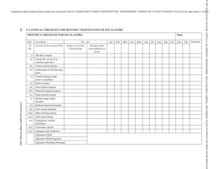


This document contains the National Building Code of India 2016: Part 7 Construction Management, Practices and Safety. It includes six sections that cover various aspects of construction management, planning, practices, safety, repairs and strengthening of buildings, as well as habitat and welfare requirements for construction workers. The sections include construction project management, construction planning and site management, construction practices, safety in construction and demolition, repairs and retrofitting of buildings, and habitat and welfare requirements for construction workers. It aims to provide guidance on best practices for construction activities and safety.


