This document is the National Building Code of India 2016 Volume 2. It contains various parts related to building construction regulations and standards in India. Specifically, this document contains Part 9 Section 1 which covers requirements for water supply systems in buildings. It includes provisions for water supply requirements, design of water supply systems, storage of water, distribution systems, and hot water supply systems. It also provides guidelines for water supply systems in high altitude and sub-zero temperature regions. The section contains annexes with application forms and completion certificates for plumbing works. Standards referenced for water supply systems are listed at the end.
![HNXGL)NL]Q N=G
+NNMUKHNXGZMNV
1, 1ÊÊ Ê-/ , -
1$7,21$/%8,/',1*2'(
2),1',$
+NNMUGKMN9K
+NRXIXHN=NODIJUN
92/80(
N0
Supplied
by
Book
Supply
Bureau
Under
the
License
from
BIS
for
LARSEN
AND
TOUBRO
CONSTRUCTION
-
MANAPAKKAM,
CHENNAI
ON
17-03-2017
09:00:59
(123.63.24.35)
valid
upto31-12-2017
ook Supply Bureau Under the License from BIS for LARSEN AND TOUBRO CONSTRUCTION - MANAPAKKAM, CHENNAI ON 17-03-2017 09:00:59 (123.63.24.35) valid up](https://image.slidesharecdn.com/nationalbuildingcode-240401165105-f4e9283c/75/NBC-National-Building-Code-volume-1-and-2-1-2048.jpg)

![PART 9 PLUMBING SERVICES (INCLUDING SOLID WASTE MANAGEMENT) — SECTION 1 WATER SUPPLY 5
2.1.7 Backflow
a) The flow of water or other liquids, mixtures
or substances into the distributing pipes of a
system of supply of potable water from any
source or sources other than its intended
source.
b) The flow of a liquid in a direction reverse of
that intended.
2.1.8 Backflow Prevention Device — Any approved
measure or fitting or combination of fittings specifically
designed to prevent backflow or back siphonage in a
water service.
2.1.9 Back Pressure Back Flow — Due to an increased
pressure above the supply pressure, which may be due
to pumps, other equipment, gravity or other source of
pressure.
2.1.10 Back Siphonage — The flowing back of used,
contaminated, or polluted water from a plumbing fixture
or vessel into a water supply due to a reduced pressure
in such pipe (see 2.1.7).
2.1.11 Barrel — This portion of a pipe in which the
diameter and wall thickness remain uniform throughout.
2.1.12 Base — The lowest portion or lowest point of a
stack of vertical pipe.
2.1.13 Bath Room Group — Group of fixtures
consisting of water closet, lavatory, bath tub or shower
and other fittings with a floor drain located together.
2.1.14 Bedding — The material on which the pipe is
laid and which provides support for the pipe. Bedding
can be concrete, granular material or the prepared
trench bottom.
2.1.15 Chair — A bed of concrete or other suitable
material on the trench floor to provide a support for
the pipes at intervals.
2.1.16 Channel — The open waterway through which
sewage, storm water or other liquid wastes flow at the
invert of a manhole or an inspection chamber.
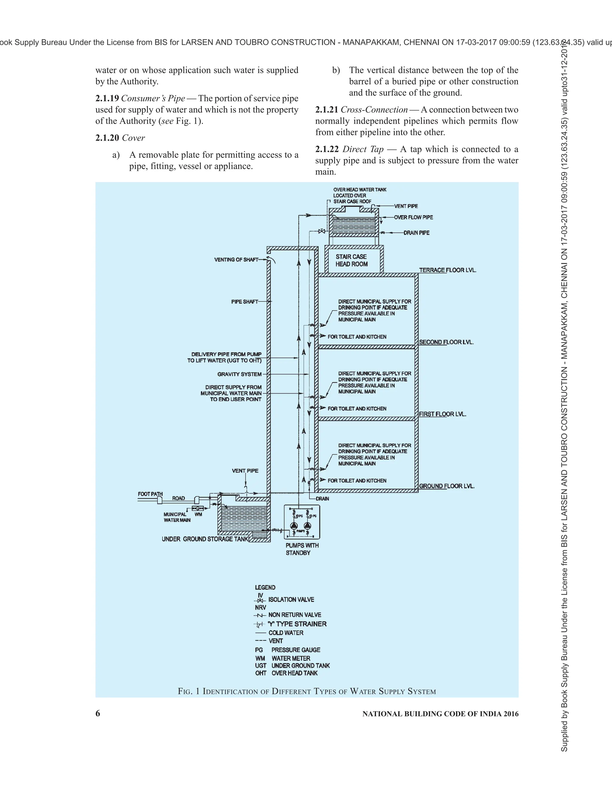
2.1.17 Communication Pipe — That part of a service
pipe which vests in the water undertakes. It starts at
the water main and terminate at a point which differs
according to the circumstances of the case.
2.1.18 Consumer — Any person who uses or is supplied
1 SCOPE
1.1 This Code (Part 9/Section 1) covers the basic
requirements of water supply for residential, business
and other types of buildings, including traffic terminal
stations. This Section also deals with general
requirements of plumbing connected to public water
supply and design of water supply systems along with
general guidelines about expansion in piping systems,
and swimming pools.
1.1.1 This Section does not take into consideration the
requirements of water supply for industrial plants and
processes, which have to be provided for separately. It
also does not provide the requirements of water supply
for other purposes, such as firefighting and street
cleaning.
2 TERMINOLOGY
For the purpose of this Section, the following definitions
shall apply in addition to the definitions given in
accepted standards [9-1(1)].
2.1 Definitions Relating to Water Supply
2.1.1 Access Panel — A removable panel mounted in a
frame, normally secured with screws and mounted in a
wall or ceiling, to provide access to concealed valves
or items which may require maintenance.
2.1.2 Air Gap, Water Distribution — Unobstructed
vertical distance through the free atmosphere between
the lowest opening from any pipe or faucet conveying
water to a tank or plumbing fixture and flood level rim
of the receptacle.
2.1.3 Air Valve — A valve that releases air from a
pipeline automatically without loss of water, or
introduce air into a line automatically if the internal
pressure becomes less than that of the atmosphere.
2.1.4 Authority Having Jurisdiction — The authority
which has been created by a statute and which for the
purpose of administering the Code/Part may authorize
a committee or an official to act on its behalf; hereinafter
called the ‘Authority’.
2.1.5 Available Head — The head of water available
at the point of consideration due to mains’ pressure or
overhead tank or any other source of pressure.
2.1.6 Anti-Siphon— A device or mechanism to prevent
siphonage.
NATIONAL BUILDING CODE OF INDIA
PART 9 PLUMBING SERVICES
(INCLUDING SOLID WASTE MANAGEMENT)
Section 1 Water Supply
Supplied
by
Book
Supply
Bureau
Under
the
License
from
BIS
for
LARSEN
AND
TOUBRO
CONSTRUCTION
-
MANAPAKKAM,
CHENNAI
ON
17-03-2017
09:00:59
(123.63.24.35)
valid
upto31-12-2017
ook Supply Bureau Under the License from BIS for LARSEN AND TOUBRO CONSTRUCTION - MANAPAKKAM, CHENNAI ON 17-03-2017 09:00:59 (123.63.24.35) valid up](https://image.slidesharecdn.com/nationalbuildingcode-240401165105-f4e9283c/75/NBC-National-Building-Code-volume-1-and-2-9-2048.jpg)
![PART 9 PLUMBING SERVICES (INCLUDING SOLID WASTE MANAGEMENT) — SECTION 1 WATER SUPPLY 11
3.3.1.1 No individual, firm, partnership or
corporation shall engage in the business of installing,
repairing or altering plumbing unless the plumbing
work performed in the course of such business is
under the direct supervision of a licensed/registered
plumber.
3.3.2 Examination and Certification
The Authority shall establish standards and procedure
for the qualification, examination and licensing/
registration of plumbers and shall issue licences to such
persons who meet the qualifications thereof and
successfully pass the examination.
3.3.3 For guidelines for registration of plumbers
including the minimum standards for qualifications for
the grant of licences/registration, reference may be
made to good practice [9-1(2)]. The Authority may also
utilize the services of the certified plumbers who are
certified for the required skill level under the
appropriate scheme of the Government.
4 WATER SUPPLY
4.1 Water Supply Requirements for Buildings
The total quantity of water per day is estimated based
on the proposed occupancy and activities catered.
Designer has to identify all the possible sources for
augmenting the shortfall in water supply. The
analysis of available water is done to decide the
treatment for consumption and treatment process
depends on the quality of water and the purpose for
which it is used.
Projection of population for each building shall be made
on the basis of its usage. Population for each type of
building shall be estimated on the basis of information
obtained from the users. Alternatively, population may
be worked on the following basis, for different type of
buildings:
a) Residential buildings:
Accommodation Population
Requirements
1 bedroom dwelling unit 4
2 bedroom dwelling unit 5
3 bedroom dwelling unit 6
4 bedroom dwelling unit
and above
7
NOTES
1 The above figures consider a domestic house-
hold including support personnel, wherever
applicable.
2 For plotted development, the population may be
arrived at after due consideration of the expected
number and type of domestic household units.
3 Dwelling unit under EWS category shall have
population requirement of 4 and studio apartment
shall have population requirement of 2.
b) Other than residential buildings:
Occupancy Population Requirement
Offices 1 person per 10 m2
of floor
area (see Note 1)
Schools Strength of school +
Teaching and non-teaching
staff
Hostels Number of beds + 4.5 x
(warden’s residence) +
staff
Hotels Number of beds + Staff +
Requirement of restaurant
seats
Hospitals Number of beds + Staff +
Patient attendants (generally
population density per bed
in secondary care hospital is
5, tertiary care is 7 and
quaternary care is 9)
Mercantile 1 person per 3 m2
of street
floor and sales basement
areas + 1 person per 6 m2
of upper sale floors
(Total population may be
segregated into 10 percent
for fixed and 90 percent
for floating/visitors)
Traffic
terminal
stations
Average number of users
per day (Total annual
passenger traffic/365) +
Staff + Vendors
NOTES
1 Wherever there are multiple work shifts, the
number of users within a 24 h period may be
considered as per actuals.
2 Population of 5 to 15 percent, depending on the
usage of building, shall be considered for visitors
and floating population likely to use the
buildings facilities.
4.1.1 Water Supply for Residences
A minimum of 70 to 100 litre per head per day may be
considered adequate for domestic needs of urban
communities, apart from non-domestic needs as
flushing requirements (which varies based on type of
building occupancy). As a general rule the following
rates per capita per day may be considered for domestic
and non-domestic needs:
a) For communities with population up to 20 000:
1) Water supply through stand: 40 lphd (Min)
post
2) Water supply through house: 70 to 100 lphd
service connection
b) For communities with: 100 to 135 lphd
population 20 000 to 100 000
together with full flushing system
Supplied
by
Book
Supply
Bureau
Under
the
License
from
BIS
for
LARSEN
AND
TOUBRO
CONSTRUCTION
-
MANAPAKKAM,
CHENNAI
ON
17-03-2017
09:00:59
(123.63.24.35)
valid
upto31-12-2017
ook Supply Bureau Under the License from BIS for LARSEN AND TOUBRO CONSTRUCTION - MANAPAKKAM, CHENNAI ON 17-03-2017 09:00:59 (123.63.24.35) valid up](https://image.slidesharecdn.com/nationalbuildingcode-240401165105-f4e9283c/75/NBC-National-Building-Code-volume-1-and-2-15-2048.jpg)
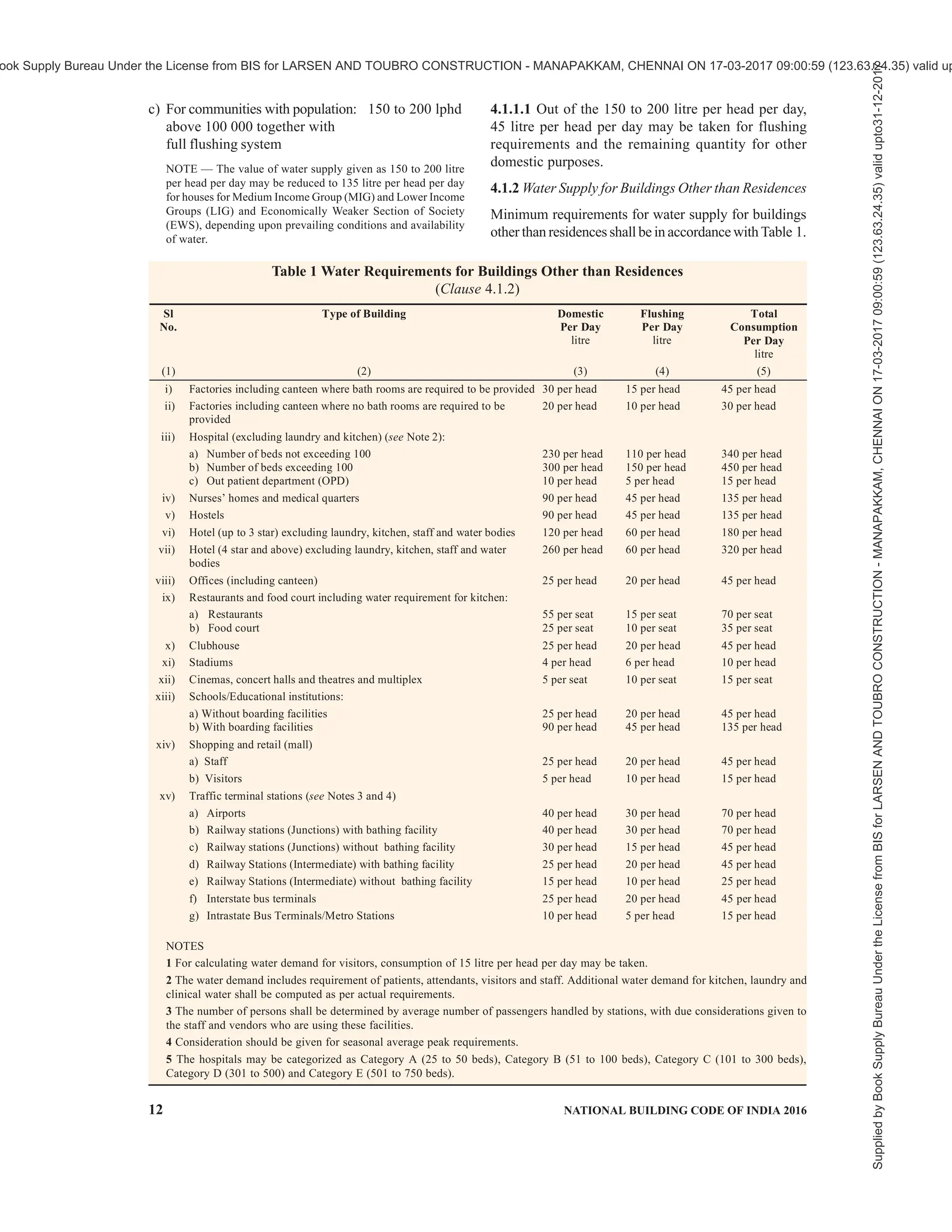
![PART 9 PLUMBING SERVICES (INCLUDING SOLID WASTE MANAGEMENT) — SECTION 1 WATER SUPPLY 13
The water demand for the laboratory facilities will
depend on actual requirements based on functional
point of view.
4.1.3 Water Supply Requirements of Traffic Terminal
Stations
The water supply requirements of traffic terminal stations
(railway stations, bus stations, harbours, airports, etc)
include provisions for waiting rooms and waiting halls.
They do not, however, include requirements for retiring
rooms. Requirements of water supply for traffic terminal
stations shall be as per Table 1.
4.1.4 Water Supply for Fire Fighting Purposes
4.1.4.1 The Authority shall make provision to meet the
water supply requirements for fire fighting in the city/
area, depending on the population density and types of
occupancy. See also Part 4 ‘Fire and Life Safety’ of the
Code.
4.1.4.2 Provision shall be made by the owner of the
building for water supply requirements for fire fighting
purposes within the building, depending upon the height
and occupancy of the building, in conformity with the
requirements laid down in Part 4 ‘Fire and Life Safety’
of the Code.
4.1.4.3 The requirements regarding water supply in
storage tanks, capacity of fire pumps, arrangements of
wet riser-cum-down comer and wet riser installations
for buildings, depending upon the occupancy use and
other factors, shall be in accordance with Part 4 ‘Fire
and Life Safety’ of the Code.
4.1.5 Water Supply for Other Purposes
4.1.5.1 Water supply in many buildings is also required
for many other applications other than domestic use,
which shall be identified in the initial stages of
planning so as to provide the requisite water quantity,
storage capacity and pressure as required for each
application. In such instances information about the
water use and the quality required may be obtained
from the users. Some typical uses other than domestic
use and fire fighting purposes are air conditioning,
swimming pools and water bodies, and gardening.
Treated water from sewage treatment plant, with
suitable tertiary treatment, should be used for flushing
purpose (with dual piping system), gardening purpose,
cooling tower make up, and/or for other non potable
usage.
4.1.5.2 The water demand for landscaping purposes is
generally taken as 6 to 8 litre/m2
/day for lawns. For
shrubs and trees the above value can be reduced
considerably.
4.2 Water Sources and Quality
4.2.1 Sources of Water
The origin of all sources of water is rainfall. Water can
be collected as it falls as rain before it reaches the
ground; or as surface water when it flows over the
ground or is pooled in lakes or ponds; or as ground
water when it percolates into the ground and flows or
collects as ground water; or from the sea.
Contamination of water supplies can occur in the source
water as well as in the distribution system after water
treatment has already occurred. There are many sources
of water contamination, including naturally occurring
chemicals and minerals (for example, arsenic, radon,
uranium), local land use practices (fertilizers,
pesticides, concentrated animal feeding operations),
manufacturing processes, and sewer overflows or
wastewater releases. The presence of contaminants in
water can lead to adverse health effects, including
gastrointestinal illness, reproductive problems, and
neurological disorders.
4.2.2 The water supplied shall be free from pathogenic
organisms, clear, free from undesirable taste and odour,
neither corrosive nor scale forming and free from
minerals which could produce undesirable
physiological effects. The quality of water to be used
for drinking shall be as per accepted standard [9-1(3)].
4.2.3 For purposes other than drinking water if
supplied separately, shall be absolutely safe from
bacteriological contamination so as to ensure that there
is no danger to the health of the users due to such
contaminants.
For purposes other than drinking, where there is an
overall risk of legionella growth, it is advisable that
for cold water supplies, the temperature does not exceed
20°C and a minimum temperature of 55°C for hot water
supplies be maintained at all points of network so as to
ensure that it is absolutely safe from bacteriological
contamination and there is no danger to the health of
the users due to such contaminants.
4.2.4 Waste Water Reclamation
Treated sewage or other waste water of the community
may be utilized for non-domestic purposes such as
water for flushing, landscape irrigation, cooling towers
of HVAC system, in fountains and recreational lakes
where swimming is not allowed, and for certain
industrial purposes after its necessary treatment to suit
the nature of the use. This supply system shall be
allowed in residences only if proper provision is made
to avoid any cross-connection of this treated waste
water with domestic water supply system. During use
of treated waste water, it is recommended to have dual
piping system to avoid cross-contamination.
4.2.4.1 Treatment of waste water and usage of recycled
water
Waste water is generated by residential and other
establishments like institutional, business, mercantile
Supplied
by
Book
Supply
Bureau
Under
the
License
from
BIS
for
LARSEN
AND
TOUBRO
CONSTRUCTION
-
MANAPAKKAM,
CHENNAI
ON
17-03-2017
09:00:59
(123.63.24.35)
valid
upto31-12-2017
ook Supply Bureau Under the License from BIS for LARSEN AND TOUBRO CONSTRUCTION - MANAPAKKAM, CHENNAI ON 17-03-2017 09:00:59 (123.63.24.35) valid up](https://image.slidesharecdn.com/nationalbuildingcode-240401165105-f4e9283c/75/NBC-National-Building-Code-volume-1-and-2-17-2048.jpg)
![14 NATIONAL BUILDING CODE OF INDIA 2016
and industrial. It includes household waste liquid from
toilets, baths, showers, kitchens and sinks that is
disposed of via sewers. Waste water treatment is the
process of removing contaminants from wastewater,
including household sewage and runoff (effluents). It
includes physical, chemical, and biological processes
to remove contaminants. Treatment of waste water and
usage of recycled waste water may be done to make it
usable for appropriate applications. The objective is to
produce an environmentally safe fluid waste stream (or
treated effluent) and a solid waste (or treated sludge)
suitable for disposal or reuse.
Separation of household waste into grey water and black
water (and draining of black water into sewerage system)
is becoming more common with grey water being
permitted to be used for watering plants or recycled for
flushing toilets after proper treatment. Waste water
collection and treatment is typically subject to statutory
regulations. Treatment depends on the characteristics of
influent and the treatment requirements that are needed
for treating the same. Waste water treatment generally
involves the following three stages:
a) Primary treatment — It consists of
temporarily holding the wastewater for
settlement of heavy solids at the bottom while
oil, grease and lighter solids float to the
surface.
b) Secondary treatment — It removes dissolved
and suspended biological matter.
c) Tertiary treatment — It is more intensive
treatment done in order to allow rejection into
a highly sensitive or fragile ecosystem. The
tertiary treatment is generally followed by
disinfection.
4.2.5 Water Conservation, Water Balance and Use of
Recycled Water
Water conservation encompasses the policies, strategies
and activities to manage fresh water as a sustainable
resource, to protect the water environment and to meet
current and future demand. Population, household size,
and growth and affluence all affect the quantity of water
used. Water balance studies should be carried out to
study the availability of water from different sources
and its usage for different purposes.
4.2.6 Whenever a building is used after long intervals,
the water quality of the stored water shall be checked
so as to ensure that the water is safe for use as per
water quality requirements specified in this Code.
4.3 Estimate of Demand Load
4.3.1 Estimates of total water supply requirements for
buildings shall be based on the occupant load consistent
with the provisions of 4.1.
4.3.2 In making assessment of water supply
requirements of large complexes, the future occupant
load shall be kept in view. The following methods may
be used for estimating future requirements:
a) Demographic method of population
projection,
b) Arithmetic progression method,
c) Geometrical progression method,
d) Method of varying increment or incremental
increase,
e) Logistic method,
f) Graphical projection method, or
g) Graphical comparison method.
4.4 Storage of Water
4.4.1 In a building, provision is required to be made
for storage of water for the following reasons:
a) To provide against interruptions of the supply
caused by repairs to mains, etc;
b) To reduce the maximum rate of demand on
the mains;
c) To tide over periods of intermittent supply;
and
d) To maintain a storage for the fire fighting
requirement of the building
4.4.2 The water may be stored in overhead tanks (OHT)
and/or underground tanks (UGT).
4.4.3 Materials Used
Reservoirs and tanks for the storage of water shall be
constructed of reinforced concrete, brick masonry,
ferrocement, mild steel, stainless steel, plastic or glass
reinforced panels.
4.4.3.1 Tanks made of steel may be of welded, riveted
or panel/pressed construction. The metal shall be
galvanized or coated externally with a good quality anti-
corrosive weather-resisting paint. Lead-based paint
shall not be used in the tank. Lead-lined tanks shall not
be used. Rectangular pressed steel tanks shall conform
to good practice [9-1(4)].
4.4.4 Each tank shall be provided with the following:
a) Manholes — Adequate number of manholes
for access and repair. The manholes shall be
made of corrosion resistant material (for
example, cast iron, reinforced cement
concrete, steel fibre reinforced concrete,
galvanized steel, high density polyethylene,
fibre glass reinforced plastic or such other
materials) acceptable to the Authority.
Manholes shall be provided with locking
arrangement to avoid misuse and tampering.
Supplied
by
Book
Supply
Bureau
Under
the
License
from
BIS
for
LARSEN
AND
TOUBRO
CONSTRUCTION
-
MANAPAKKAM,
CHENNAI
ON
17-03-2017
09:00:59
(123.63.24.35)
valid
upto31-12-2017
ook Supply Bureau Under the License from BIS for LARSEN AND TOUBRO CONSTRUCTION - MANAPAKKAM, CHENNAI ON 17-03-2017 09:00:59 (123.63.24.35) valid up](https://image.slidesharecdn.com/nationalbuildingcode-240401165105-f4e9283c/75/NBC-National-Building-Code-volume-1-and-2-18-2048.jpg)
![PART 9 PLUMBING SERVICES (INCLUDING SOLID WASTE MANAGEMENT) — SECTION 1 WATER SUPPLY 17
c) Ductile iron, internally lined;
d) Reinforced concrete;
e) Prestressed concrete;
f) Galvanized mild steel tubes;
g) Copper;
h) Brass;
j) Wrought iron;
k) Stainless steel;
m) Polyethylene;
n) Unplasticized PVC;
p) Chlorinated PVC;
q) Polypropylene-random copolymer (PPR);
r) Composite pipes (PE-AL-PE) or any other
combination;
s) Cross-linked polyethylene (PEX); or
t) Polybutylene pipe.
4.6.2.1 The material chosen shall be resistant to
corrosion, both inside and outside or shall be suitably
protected against corrosion.
4.6.2.2 Polyethylene and unplasticized PVC pipes shall
not be installed near hot water pipes or near any other
heat sources. For temperature limitations in the use of
polyethylene and unplasticized PVC pipes to convey
water, reference may be made to accepted standards
[9-1(5)].
4.7 Design of Distribution Systems
4.7.1 General
For designing the distribution system, the following
guidelines, in addition to those given in 4.7.2 to 4.7.6
shall be followed:
a) Allplumbingsystemsinbuildingsshallconform
to the general requirements given in 3.1.
b) Peak factor for calculation in case of
intermittent flows may generally be adopted
in design as 2 to 3.
c) The residual head at consumer’s tap shall be
as per 3.1.2.
4.7.2 Rate of Flow
One of the important items that needs to be determined
before the sizes of pipes and fittings for any part of the
water piping system may be decided upon, is the rate
of flow in the service pipe which in turn depends upon
the number of hours for which the supply is available
at sufficiently high pressure. If the number of hours for
which the supply is available is less, there will be large
number of fittings in use simultaneously and the rate
of flow will be correspondingly large.
The data required for determining the size of the
communication and service pipes are,
a) the maximum rate of discharge required;
b) the length of the pipe; and
c) the head loss by friction in pipes, fittings and
meters.
4.7.3 Discharge Computation
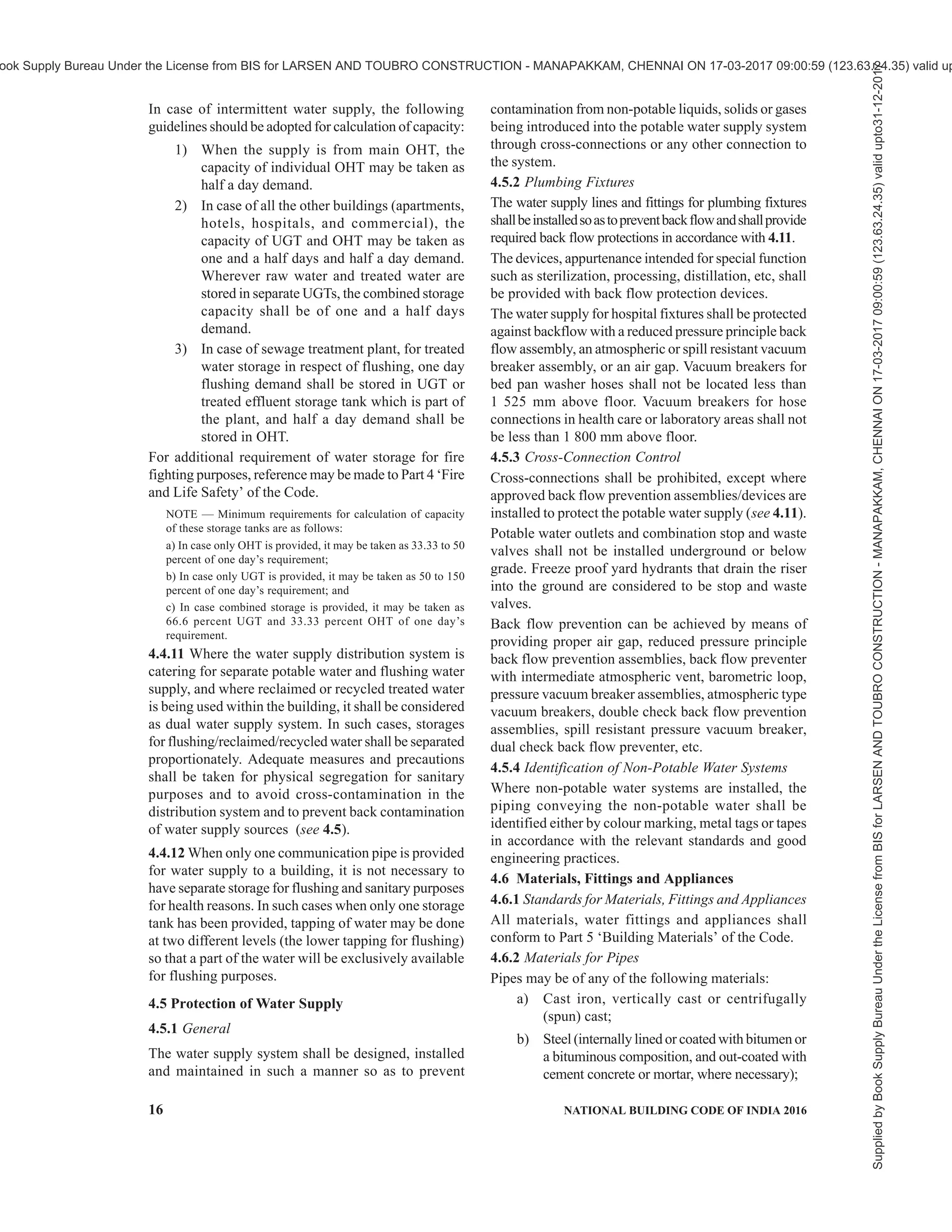
4.7.3.1 Design of consumer’s pipes based on fixture units
The design of the consumers’ pipes or the supply pipe
to the fixtures is based on,
a) the number and kind of fixtures installed;
b) the fixture unit flow rate; and
c) the probable simultaneous use of these
fixtures.
The rates at which water is desirably drawn into
different types of fixtures are known. These rates
become whole numbers of small size when they are
expressed in fixture unit.
The water supply fixture units (WSFU) for different
sanitary appliances or groups of appliances are given
in Table 2.
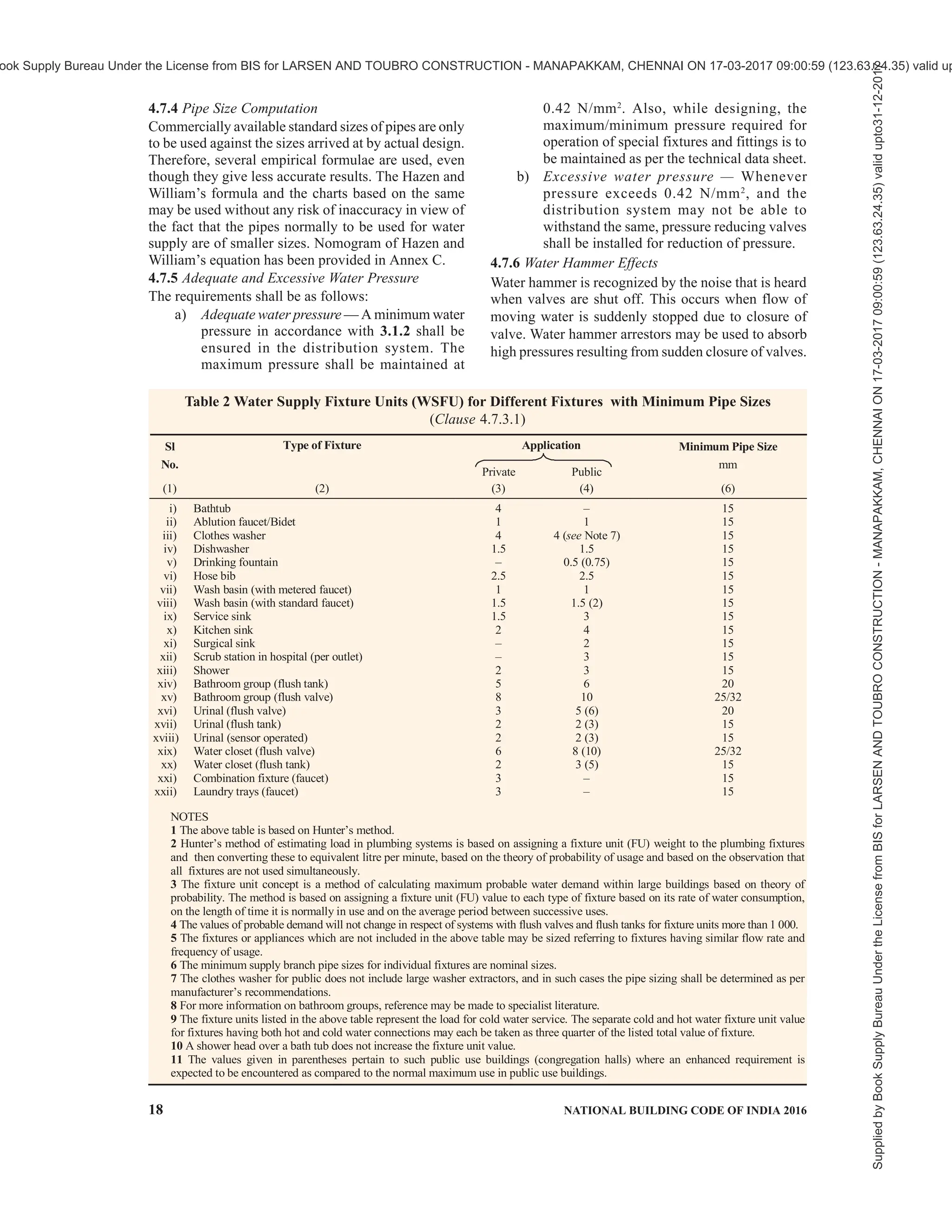
4.7.3.2 Probable simultaneous demand
The possibility that all water supply taps in any system
in domestic and commercial use will draw water at the
same time is extremely remote. Designing the water
mains for the gross flow will result in bigger and
uneconomical pipe mains and may not be necessary. A
probability study made by Hunter suggests the
relationship shown in Fig. 2 and Table 3. In the absence
of similar studies in India, the curves based on Hunter’s
study may be followed. In making use of these curves,
special allowances are made as follows:
a) Demands for service sinks are ignored in
calculating the total fixture demand.
b) Demands of supply outlets such as hose
connections and air conditioners through
which water flows more or less continuously
over a considerable length of time shall be
added to the probable flow rather than the
fixture demand.
c) Fixtures supplied with both hot and cold water
exert reduced demands upon main hot water
and cold water branches (not fixture branches).
4.7.3.3 The maximum flow rate and flush volumes shall
be as given below:
Plumbing Fixtures/Fittings Maximum
Flow Rate
Water closets 6 litre/flush
Urinals 3.8 litre/flush
Lavatory, metered faucet (Public) 1 litre/use
Lavatory, faucet (Private) 8 litre/min
Sink, faucet 8 litre/min
Bidet, hand held spray 8 litre/min
Shower head 10 litre/min
NOTE — The maximum flow rates of plumbing fixtures
and fittings provided are at the pressure of 0.42 N/mm 2
.
Water closet with dual flush cistern and urinals with
reduced flush volumes are recommended. Further, users/
designers are encouraged to use low flow fixtures.
Supplied
by
Book
Supply
Bureau
Under
the
License
from
BIS
for
LARSEN
AND
TOUBRO
CONSTRUCTION
-
MANAPAKKAM,
CHENNAI
ON
17-03-2017
09:00:59
(123.63.24.35)
valid
upto31-12-2017
ook Supply Bureau Under the License from BIS for LARSEN AND TOUBRO CONSTRUCTION - MANAPAKKAM, CHENNAI ON 17-03-2017 09:00:59 (123.63.24.35) valid up](https://image.slidesharecdn.com/nationalbuildingcode-240401165105-f4e9283c/75/NBC-National-Building-Code-volume-1-and-2-21-2048.jpg)
![PART 9 PLUMBING SERVICES (INCLUDING SOLID WASTE MANAGEMENT) — SECTION 1 WATER SUPPLY 19
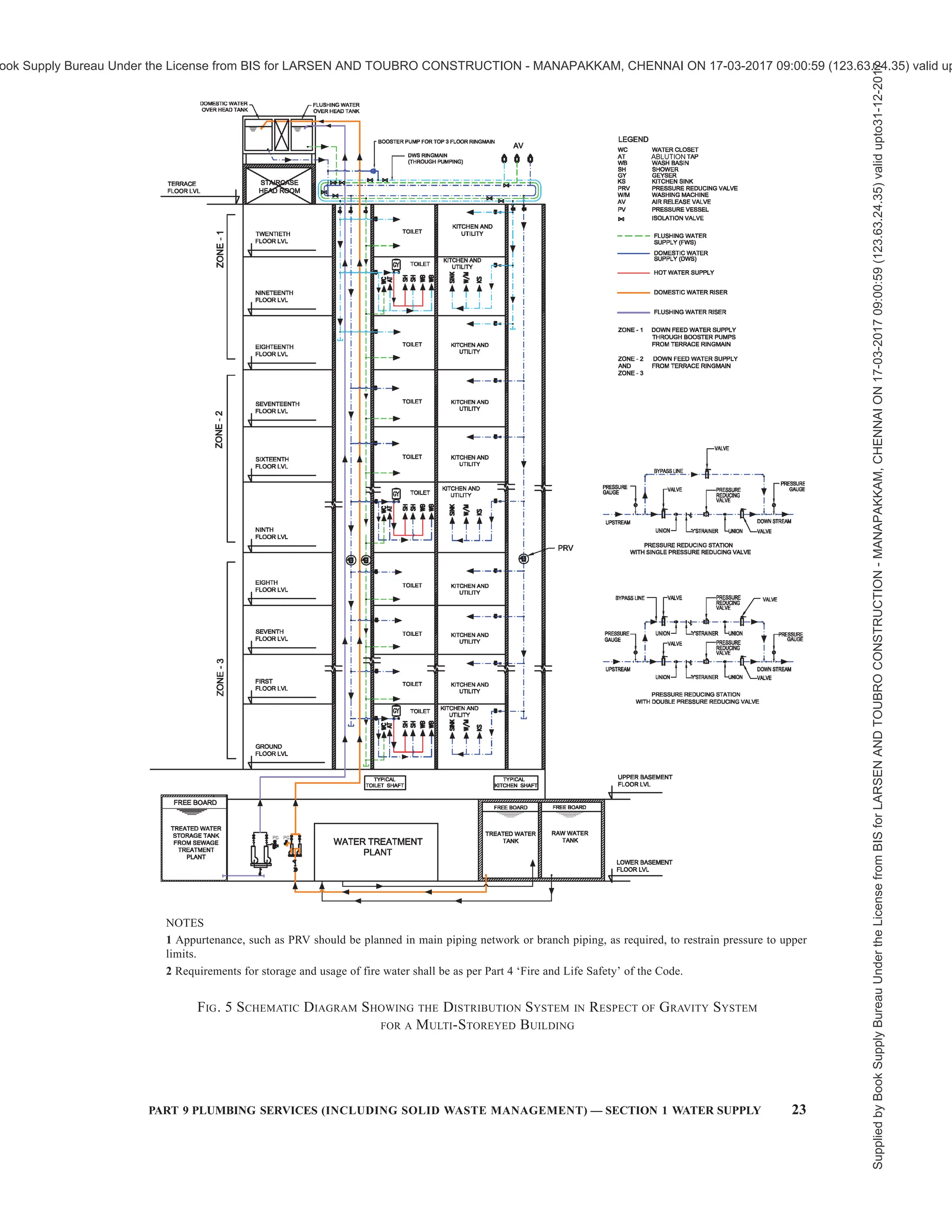
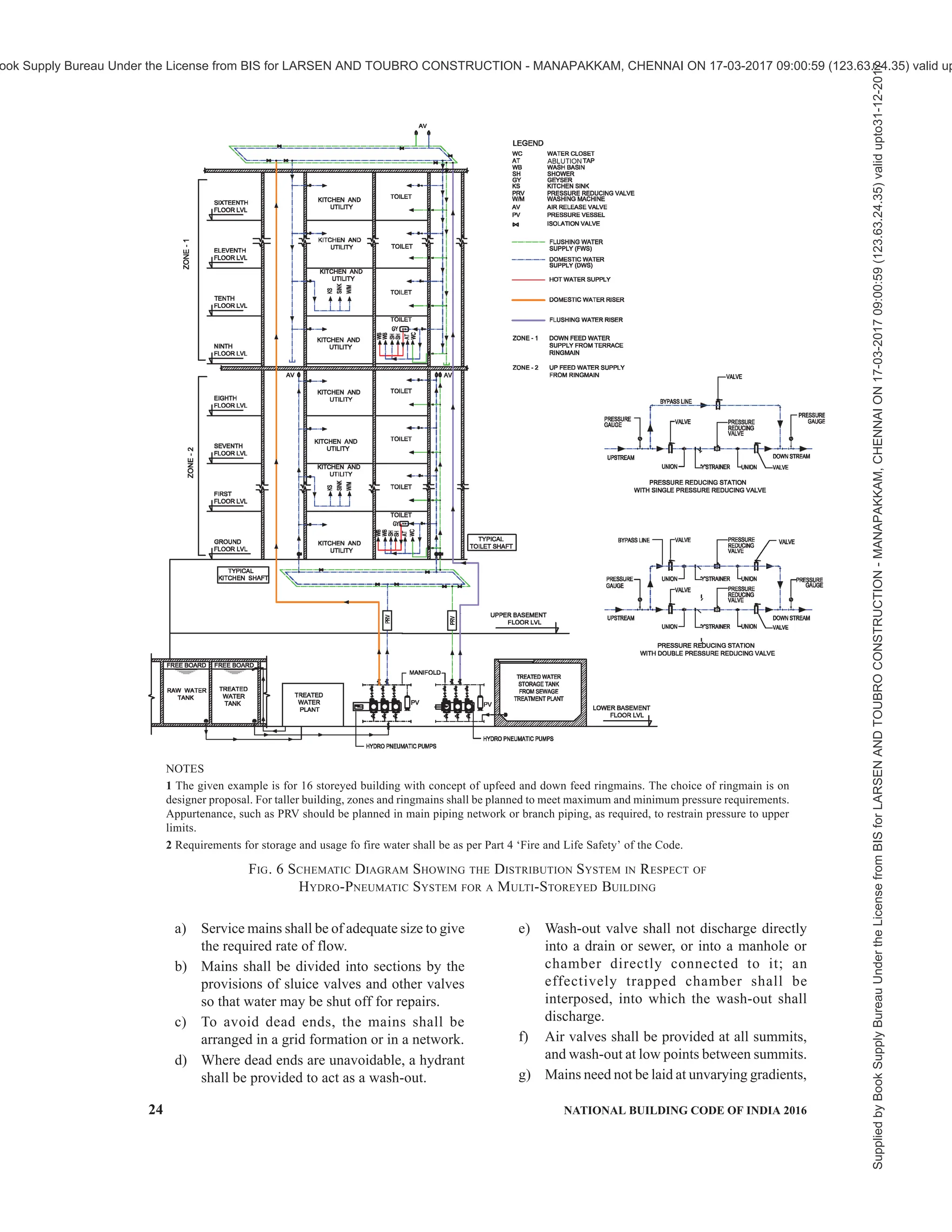
4.8 Distribution Systems in Multi-Storeyed
Buildings
4.8.1 There are following four basic methods of
distribution of water to a multi-storeyed buildings:
a) Direct supply system from mains — public or
private.
b) Gravity distribution system.
c) Pressurized distribution system (Hydro-
pneumatic pumping system).
d) Combined distribution system.
4.8.2 Direct Supply System from Mains — Public or
Private
This system is adopted when adequate pressure is
available in the mains to supply water at adequate
pressure at the topmost floor. With limited pressure
available in most city mains, water from direct supply
is normally not available above two or three floors.
However, in gated communities or large campuses, this
system can be adopted for taller buildings by
incorporating design parameters such as elevated
centralized water tank(s) or central hydro-pneumatic
pumping system(s). For details of this system, reference
may be made to good practice [9-1(6)] may be referred.
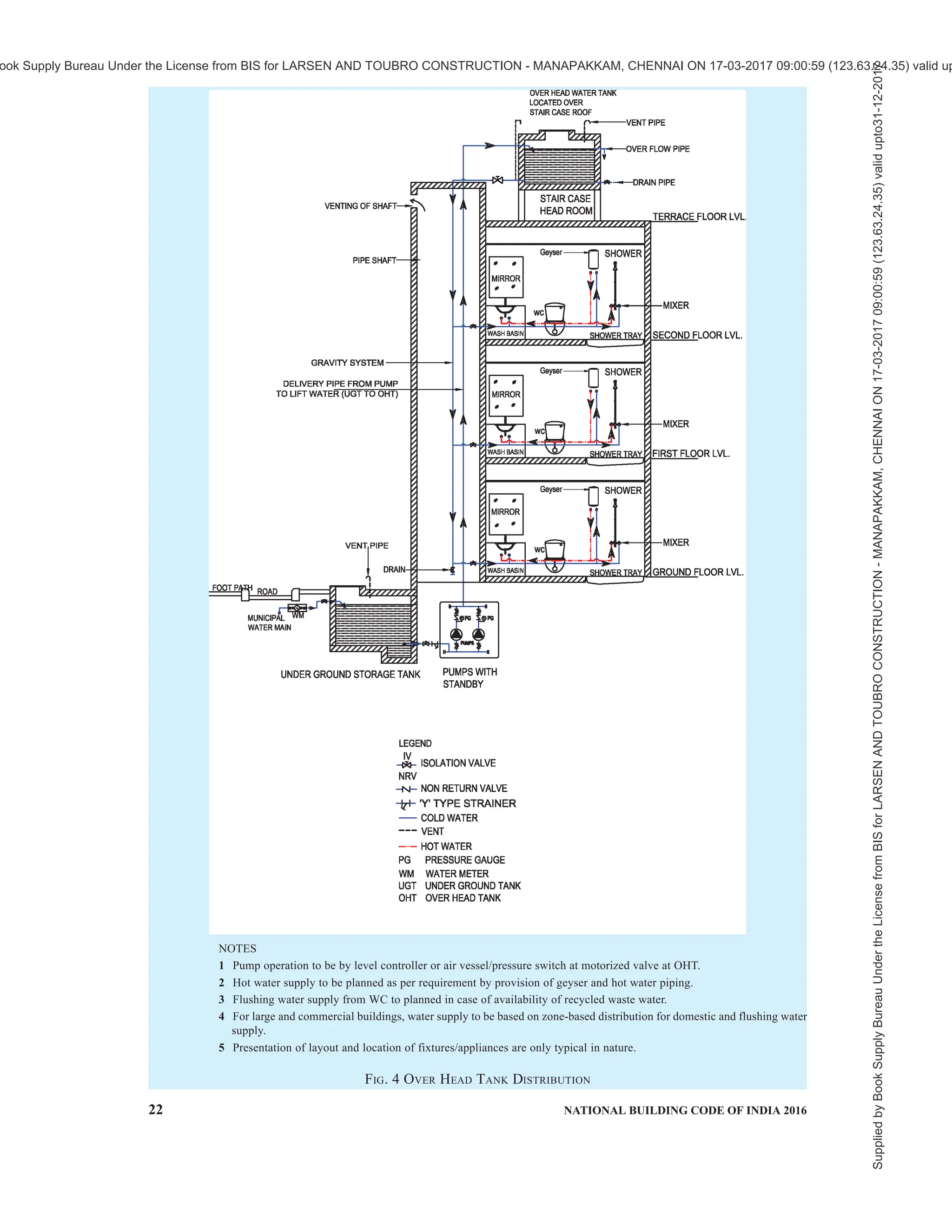
4.8.3 Gravity Distribution System
This is the most common water distribution system.
The system comprises pumping water to one or more
overhead water tanks. Water transferred to overhead
tank(s) is distributed by gravity to various parts of the
building by the system of piping network.
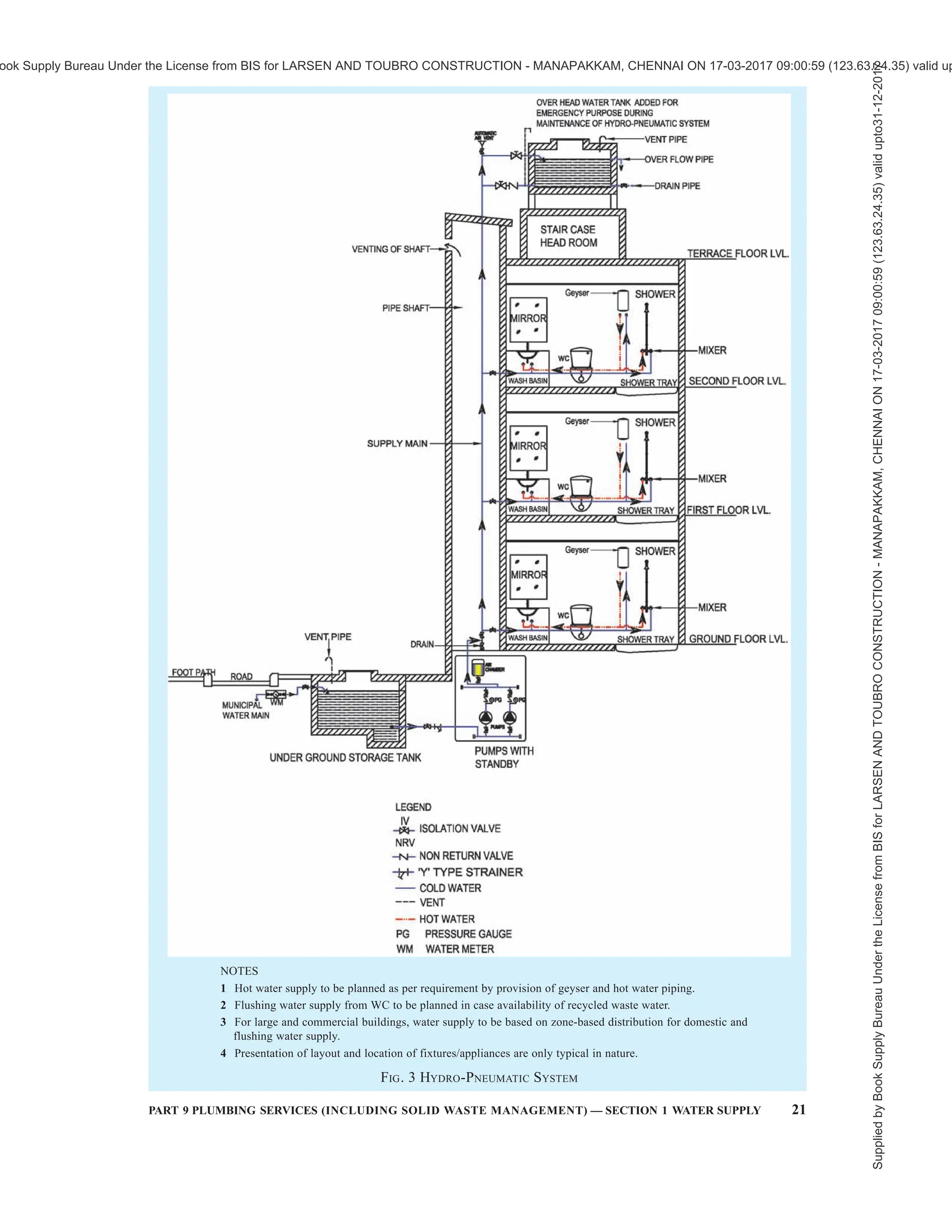
4.8.4 Pressurized Distribution System (Hydro-
pneumatic Pumping System)
4.8.4.1 Pressurized distribution system is a direct
pumping system incorporating a recharge diaphragm
vessel.
2A GRAPH FOR PROBABLE DEMAND UP TO 10 000 FU
2B GRAPH FOR PROBABLE DEMAND UP TO 1 000 FU
Curve 1 — System With Flush Valves
Curve 2 — System With Flush Tanks
FIG. 2 GRAPH FOR PROBABLE DEMAND
Supplied
by
Book
Supply
Bureau
Under
the
License
from
BIS
for
LARSEN
AND
TOUBRO
CONSTRUCTION
-
MANAPAKKAM,
CHENNAI
ON
17-03-2017
09:00:59
(123.63.24.35)
valid
upto31-12-2017
ook Supply Bureau Under the License from BIS for LARSEN AND TOUBRO CONSTRUCTION - MANAPAKKAM, CHENNAI ON 17-03-2017 09:00:59 (123.63.24.35) valid up](https://image.slidesharecdn.com/nationalbuildingcode-240401165105-f4e9283c/75/NBC-National-Building-Code-volume-1-and-2-23-2048.jpg)
![26 NATIONAL BUILDING CODE OF INDIA 2016
consequent danger of contamination and
depletion of storage capacity. It might also
result in pipes and fittings being subjected to
a pressure higher than that for which they are
designed, and in flooding from overflowing
cisterns.
b) No pipe for conveyance or in connection with
water supplied by the Authority shall
communicate with any other receptacle used
or capable of being used for conveyance other
than water supplied by the Authority.
c) Where storage tanks are provided, no person
shall connect or be permitted to connect any
service pipe with any distributing pipe.
d) No service or supply pipe shall be connected
directly to any water-closet or a urinal. All
such supplies shall be from flushing cisterns/
flush valves which shall be supplied from
storage tank.
e) No service or supply pipe shall be connected
directly to any hot water system or to any other
apparatus used for heating other than through
a feed cistern thereof.
4.10 Jointing of Pipes
4.10.1 Cast Iron Pipes
Jointing may be done by any of the following methods:
a) Spigot and socket joints, or
b) Flanged joints.
in accordance with good practice [9-1(7)]. The lead
shall conform to the accepted standards
[9-1(8)].Alternative jointing materials which are found
to be equally effective, may be used in place of lead
joints, with the approval of the Authority.
4.10.2 Steel Pipes
Plain-ended steel pipes may be jointed by welding.
Electrically welded steel pipes shall be jointed in
accordance with good practice [9-1(9)].
4.10.3 Wrought Iron and Steel Screwed Pipes
Screwed wrought iron or steel piping may be jointed
with screwed and socketed joints. Care shall be taken
to remove any burr from the end of the pipes after
screwing. A jointing compound approved by the
Authority and containing no red lead composition shall
be used. Screwed wrought iron or steel piping may also
be jointed with screwed flanges.
4.10.4 Asbestos Cement Pipes
Asbestos cement pipes may be jointed in accordance
with good practice [9-1(10)].
4.10.5 Copper Pipes
Copper pipes shall be jointed by internal solder ring
joint, end-brazing joint or by use of compression fitting.
The flux used shall be non-toxic and the solder used
shall be lead free. The use of dezincification fittings
shall be made in case of jointing of copper pipe and
steel pipe. The jointing technology shall be used as per
good engineering practice and as per manufacturers
recommendations.
4.10.6 Concrete Pipes
Concrete pipes shall be jointed in accordance with good
practice [9-1(11)].
4.10.7 Polyethylene and Unplasticized PVC Pipes
Polyethylene and unplasticized PVC pipes shall be
jointed in accordance with good practice[9-1(12)].
4.11 Backflow Prevention
4.11.1 The installation shall be such that water delivered
is not liable to become contaminated or that
contamination of the public water supply does not
occur.
4.11.2 The various types of piping and mechanical
devices acceptable for backflow protection are:
a) Barometric loop,
b) Air gap,
c) Atmosphere vacuum breaker,
d) Pressure vacuum breaker,
e) Double check valve, and
f) Reduced pressure backflow device.
4.11.3 The installation shall not adversely affect
drinking water,
a) by materials in contact with the water being
unsuitable for the purpose;
b) as a result of backflow of water from water
fittings, or water using appliances into
pipework connected to mains or to other
fittings and appliances;
c) by cross-connection between pipes conveying
water supplied by the water undertaker with
pipes conveying water from some other
source; and
d) by stagnation, particularly at high
temperatures.
4.11.4 No pump or similar apparatus, the purpose of
which is to increase the pressure in or rate of flow from
a supply pipe or any fitting or appliance connected to a
supply pipe, shall be connected unless the prior written
permission of the water supplier has been obtained in
each instance.
Supplied
by
Book
Supply
Bureau
Under
the
License
from
BIS
for
LARSEN
AND
TOUBRO
CONSTRUCTION
-
MANAPAKKAM,
CHENNAI
ON
17-03-2017
09:00:59
(123.63.24.35)
valid
upto31-12-2017
ook Supply Bureau Under the License from BIS for LARSEN AND TOUBRO CONSTRUCTION - MANAPAKKAM, CHENNAI ON 17-03-2017 09:00:59 (123.63.24.35) valid up](https://image.slidesharecdn.com/nationalbuildingcode-240401165105-f4e9283c/75/NBC-National-Building-Code-volume-1-and-2-30-2048.jpg)
![28 NATIONAL BUILDING CODE OF INDIA 2016
smooth as possible inside. Methods of jointing shall
be such as to avoid internal roughness and projection
at the joints, whether of the jointing materials or
otherwise.
4.12.9Changeindiameterandindirectionshallpreferably
be gradual rather than abrupt to avoid undue loss of head.
No bend or curve in piping shall be made which is likely
to materially diminish or alter the cross-section.
4.12.10 No boiler for generating steam or closed
boilers of any description or any machinery shall be
supplied direct from a service or supply pipe. Every
such boiler or machinery shall be supplied from a feed
cistern.
4.13 Laying of Mains and Pipes on Site
4.13.1 The mains and pipes on site shall be laid in
accordance with good practice [9-1(13)]. The pipes laid
in buildings situated in seismic zone and across large
building expansion joints should be installed with
suitable expansion bellows and expansion loops to
mitigate expansion of piping system for its intended
function without failures.
4.13.2 Excavation and Refilling
The bottoms of the trench excavations shall be so
prepared that the barrels of the pipes, when laid, are
well bedded for their whole length on a firm surface
and are true to line and gradient. In the refilling of
trenches, the pipes shall be surrounded with fine
selected material, well rammed so as to resist
subsequent movement of the pipes. No stones shall be
in contact with the pipes; when resting on rock, the
pipes shall be bedded on fine-selected material or
(especially where there is a steep gradient) on a layer
of concrete.
4.13.2.1 The pipes shall be carefully cleared of all
foreign matter before being laid.
4.13.3 Laying Underground Mains
Where there is a gradient, pipe laying shall proceed in
‘uphill’ direction to facilitate joint making.
4.13.3.1 Anchor blocks shall be provided to withstand
the hydraulic thrust.
4.13.4 Iron surface boxes shall be provided to give
access to valves and hydrants and shall be supported
on concrete or brickwork which shall not be allowed
to rest on pipes.
4.13.5 Laying Service Pipes
4.13.5.1 Service pipes shall be connected to the mains
by means of right-hand screw down ferrule or
T-branches. The ferrules shall conform to accepted
standards [9-1(14)].
4.13.5.2 Precaution against contamination of the mains
shall be taken when making a connection and, where
risk exists, the main shall be subsequently disinfected.
The underground water service pipe and the building
sewer or drain shall be kept at a sufficient distance apart
so as to prevent contamination of water. Water service
pipes or any underground water pipes shall not be run
or laid in the same trench as the drainage pipe. Where
this is unavoidable, the following conditions shall be
fulfilled:
a) The bottom of the water service pipe, at all
points, shall be at least 300 mm above the top
of the sewer line at its highest point.
b) The water service pipe shall be placed on a
solid shelf excavated on one side of the
common trench.
c) The number of joints in the service pipe shall
be kept to a minimum.
d) The materials and joints of sewer and water
service pipe shall be installed in such a manner
and shall possess such necessary strength and
durability as to prevent the escape of solids,
liquids and gases there from under all known
adverse conditions, such as corrosion strains
due to temperature changes, settlement,
vibrations and superimposed loads.
4.13.5.3 The service pipe shall pass into or beneath the
buildings at a depth of not less than 750 mm below the
outside ground level and, at its point of entry through
the structure, it shall be accommodated in a sleeve
which shall have previously been solidly built into the
wall of the structure. The space between the pipe and
the sleeve shall be filled with bituminous or other
suitable material for a minimum length of 150 mm at
both ends.
4.13.6 Pipes Laid through Ducts, Chases, Notches or
Holes
Ducts or chases in walls for piping shall be provided
during the building of the walls. If they are cut into
existing walls, they shall be finished sufficiently smooth
and large enough for fixing the piping.
4.13.6.1 Piping laid in notches or holes shall not be
subjected to external pressure.
4.13.7 Lagging of Pipes
Where lagged piping outside buildings is attached to
walls, it shall be entirely covered all round with water-
proof and fire insulating material and shall not be in
direct contact with the wall. Where it passes through a
wall, the lagging shall be continued throughout the
thickness of the wall.
Supplied
by
Book
Supply
Bureau
Under
the
License
from
BIS
for
LARSEN
AND
TOUBRO
CONSTRUCTION
-
MANAPAKKAM,
CHENNAI
ON
17-03-2017
09:00:59
(123.63.24.35)
valid
upto31-12-2017
ook Supply Bureau Under the License from BIS for LARSEN AND TOUBRO CONSTRUCTION - MANAPAKKAM, CHENNAI ON 17-03-2017 09:00:59 (123.63.24.35) valid up](https://image.slidesharecdn.com/nationalbuildingcode-240401165105-f4e9283c/75/NBC-National-Building-Code-volume-1-and-2-32-2048.jpg)
![PART 9 PLUMBING SERVICES (INCLUDING SOLID WASTE MANAGEMENT) — SECTION 1 WATER SUPPLY 31
and not lower than the immersion heater.
e) Dual heater installations — If desired, the
principle of the dual heater may be adopted.
In this case, one heater and its thermostat shall
be installed at a low level as indicated in (b)
and (c). The second heater and its thermostat
shall be similarly disposed in the upper half
of the cylinder at a level depending on the
reserve of hot water desired for ordinary
domestic use. The bottom heater shall be under
separate switch control.
f) Clearance around storage vessel — Adequate
clearance shall be provided between the tank
and the cupboard, door or walls to allow
convenient insertion and adjustment of the
immersion heater and thermostat and to give
space for thermal insulation.
4.14.8.2 Rating of immersion heaters
The rating of an immersion heater shall be determined
according to the following factors:
a) Proposed hot water storage capacity (the
maximum with cold water as indicated
in 4.14.3 shall be taken into account),
b) Rate of utilization (draw off frequency),
c) Permissible recovery period, and
d) Inlet water temperature.
For details regarding rated input of water, refer to good
practice [9-1(15)].
4.14.9 Thermal Insulation
The hot water storage vessel and pipes shall be
adequately insulated, wherever necessary to minimize
heat loss. The whole external surface of the storage
vessel including the cover to the man hole shall also be
duly insulated.
Insulation may be provided by wrapping storage vessel
and pipes with fibre glass, mineral wool or closed cell
flexible elastomeric foam based materials of desired
thickness, covered with cladding for protection from
damage or from weather in case of external use.
4.14.10 Cold Water Supply to Heaters
4.14.10.1 A storage water heater (pressure type) shall
be fed from a cold water storage tank and under no
circumstances connected directly to the water main,
except the type which incorporates a feed tank with
ball valves and overflow pipe arrangement (cistern type
heaters) or non-pressure type heaters.
4.14.10.2 Storage cisterns
4.14.10.2.1 The storage capacity of a cold water tank
shall be at least twicethe capacity of the hot water heater.
The capacity of the storage tank may, however, be 1.5
times when the number of heaters connected to one
common tank exceeds 10.
4.14.10.2.2 The storage tank for supply of cold water
to hot water heaters shall be separate, if practicable. In
the case of a common tank which also supplies cold
water to the fixtures, this cold water supply connection
shall be so arranged that 50 percent of the net capacity,
worked out as in 4.14.10.2.1, shall be available for
supply to the hot water heaters.
4.14.10.2.3 In the case of multi-storeyed buildings
where a common overhead tank over the stair/lift well
is generally installed, it is advisable to have one or more
local tanks for supply to the hot water heaters or a
compartment in the tank with required storage always
available for hot water heater.
4.14.10.2.4 In tall multi-storeyed buildings where the
static pressure increases with the height, the total static
pressure on the hot water heaters on the lowest floor
shall not exceed the rated working pressure of the hot
water heater installed. Should the height of the building
so require, additional tanks shall be provided on the
intermediate floors to restrict the static head to
permissible limits or the pressure shall be reduced to
working pressure by providing pressure reducing
valves.
4.14.10.2.5 As an alternative to the arrangements stated
in 4.14.10.2.3 and 4.14.10.2.4, an individual storage
tank in each flat may be provided for supply to hot
water heaters.
4.14.11 Cold Water Feed
4.14.11.1 The feed pipe connecting cold water tank with
the hot water heater shall not be of less than 20 mm
bore and it shall leave the cold water tank at a point not
less than 50 mm above the bottom of the tank and shall
connect into the hot water heater near its bottom. The
feed pipe shall not deliver cold water to any other
connection, but into the hot water cylinders only.
4.14.11.2 In the case of multi-storeyed buildings, a
common cold water feed pipe may be installed, but
each hot water heater shall be provided with a check
valve (horizontal type check valve shall be preferred
to vertical type for easy maintenance).
4.14.11.3 Care shall be taken in installing the piping to
prevent air locks in the piping and negative pressure in
the hot water heater. Cold water feed pipe shall not be
cross-connected with any other source of supply under
pressure.
4.14.12 Hot Water Piping
4.14.12.1 Expansion pipe or vent pipe
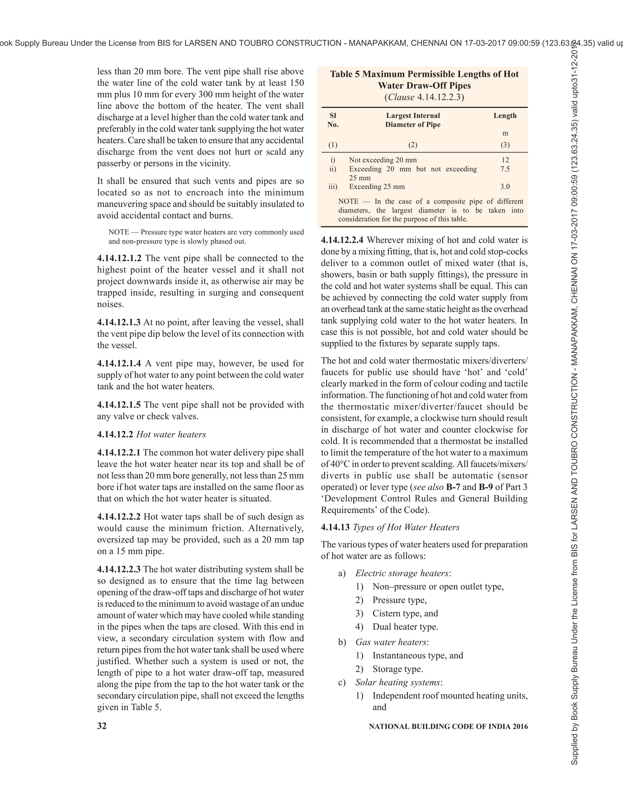
4.14.12.1.1 Each non-pressure type hot water heater
or cylinder shall be provided with a vent pipe of not
Supplied
by
Book
Supply
Bureau
Under
the
License
from
BIS
for
LARSEN
AND
TOUBRO
CONSTRUCTION
-
MANAPAKKAM,
CHENNAI
ON
17-03-2017
09:00:59
(123.63.24.35)
valid
upto31-12-2017
ook Supply Bureau Under the License from BIS for LARSEN AND TOUBRO CONSTRUCTION - MANAPAKKAM, CHENNAI ON 17-03-2017 09:00:59 (123.63.24.35) valid up](https://image.slidesharecdn.com/nationalbuildingcode-240401165105-f4e9283c/75/NBC-National-Building-Code-volume-1-and-2-35-2048.jpg)
![PART 9 PLUMBING SERVICES (INCLUDING SOLID WASTE MANAGEMENT) — SECTION 1 WATER SUPPLY 33
2) Centrally banked heated system.
d) Central hot water system:
1) Oil fired,
2) Gas fired,
3) Electrical coil type, and
4) Heat Pump.
4.14.13.1 The quality and construction of the different
types of hot water heaters shall be in accordance with
good practice [9-1(16)].
4.14.13.2 Requirements in regard to inspection and
maintenance of hot water supply installations shall be
in accordance with 4.15.1 to 4.15.4.
4.15 Inspection and Testing
4.15.1 Testing of Mains before Commencing Work
All pipes, fittings and appliances shall be inspected,
before delivery at the site to see whether they conform
to accepted standards. All pipes and fittings shall be
inspected and tested by the manufacturers at their
factory and shall comply with the requirements of this
Section. They shall be tested hydraulically under a
pressure equal to twice this maximum permissible
working pressure or under such greater pressure as may
be specified. The pipes and fittings shall be inspected
on site before laying and shall be sounded to disclose
cracks. Any defective items shall be clearly marked as
rejected and forthwith removed from the site.
4.15.2 Testing of Mains after Laying
After laying and jointing, the main shall be slowly and
carefully charged with water by providing a 25 mm
inlet with a stop-cock, so that all air is expelled from
the main. The main is then allowed to stand full of water
for a few days if time permits, and then tested under
pressure. The test pressure shall be 0.5 N/mm2
or double
the maximum working pressure, whichever is greater.
The pressure shall be applied by means of a manually
operated test pump, or, in the case of long mains or
mains of a large diameter, by a power-driven test pump,
provided the pump is not left unattended. In either case,
due precaution shall be taken to ensure that the required
test pressure is not exceeded. Pressure gauges shall be
accurate and shall preferably have been recalibrated
before the test. The pump having been stopped, the
test pressure shall maintain itself without measurable
loss for at least 5 min. The mains shall be tested in
sections as the work of laying proceeds; it is an
advantage to have the joints exposed for inspection
during the testing. The open end of the main may be
temporarily closed for testing under moderate pressure
by fitting a water-tight expanding plug of which several
types are available. The end of the main and the plug
shall be secured by struts or otherwise, to resist the
end thrust of the water pressure in the mains.
4.15.2.1 If the section of the main tested terminates
into a sluice valve, the wedge of the valve shall not be
used to retain the water; instead the valve shall be
temporarily fitted with a blank flange, or, in the case of
a socketed valve, with a plug, and the wedge placed in
the open position while testing. End support shall be
given as in 4.15.2.
4.15.3 Testing of Service Pipes and Fittings
When the service pipe is complete, it shall be slowly
and carefully charged with water, allowing all air to
escape, care being taken to avoid all shock or water
hammer. The service pipe shall then be inspected under
working conditions of pressure and flow. When all
draw-offs taps are closed, the service pipe shall be
absolutely water-tight. All piping, fittings and
appliances shall be checked for satisfactory support,
and protection from damage, corrosion and frost.
Because of the possibility of damage in transit, cisterns
shall be re-tested for water-tightness on arrival at the
site, before fixing.
4.15.4 In addition to the provisions given in 4.15.1,
provisions given in 4.15.4.1 to 4.15.4.3 shall also apply
to hot water supply installations in regard to inspection
and testing.
4.15.4.1 Testing of the system after installation
After the hot water system, including the hot water
heaters, has been installed, it shall be carefully charged
with water, so that all air is expelled from the system.
The entire system shall then be hydraulically tested to
a pressure of 0.5 N/mm2
or twice the working pressure,
whichever is greater, for a period of at least 30 min
after a steady state is reached. The entire installation
shall then be inspected visually for leakages, and
sweating. All defects found shall be rectified by
removing and remaking the particular section. Caulking
of threads, hammering and welding of leaking joints
shall not be allowed.
4.15.4.2 Hot water testing
After the system has been proved water-tight, the hot
water heaters shall be commissioned by connecting the
same to the electrical supply. The system shall then be
observed for leakage in pipes due to expansion or
overheating. The temperature of water at outlets shall
be recorded. The thermostats of the appliances shall
be checked and adjusted to temperatures specified
in 4.14.2.1.
4.15.4.3 Electrical connection
For relevant provisions regarding general and safety
requirements for household and similar electrical
appliances, reference may be made to good practice
Supplied
by
Book
Supply
Bureau
Under
the
License
from
BIS
for
LARSEN
AND
TOUBRO
CONSTRUCTION
-
MANAPAKKAM,
CHENNAI
ON
17-03-2017
09:00:59
(123.63.24.35)
valid
upto31-12-2017
ook Supply Bureau Under the License from BIS for LARSEN AND TOUBRO CONSTRUCTION - MANAPAKKAM, CHENNAI ON 17-03-2017 09:00:59 (123.63.24.35) valid up](https://image.slidesharecdn.com/nationalbuildingcode-240401165105-f4e9283c/75/NBC-National-Building-Code-volume-1-and-2-37-2048.jpg)
![34 NATIONAL BUILDING CODE OF INDIA 2016
[9-1(15)]. The metal work of the water heating
appliances and installation other than current carrying
parts shall be bonded and earthed in conformity with
the good practice [9-1(15)]. It should be noted that
screwing of an immersion heater into a tank or cylinder
cannot be relied upon to effect a low resistance earth
connection, a satisfactory separate earthing of heater
should be effected.
4.16 Cleaning and Disinfection of the Supply System
4.16.1 All water mains communications pipes, service
pipes and pipes used for distribution of water for
domestic purposes shall be thoroughly and efficiently
disinfected before being taken into use and also after
every major repair. The method of disinfection shall be
subject to the approval of the Authority. The pipes shall
also be periodically cleaned at intervals, depending upon
thequalityofwater,communicationpipesandthestorage
cisterns shall be thoroughly cleaned at least once every
year in order to remove any suspended impurities that
may have settled in the pipes or the tanks.
4.16.2 Disinfection of Storage Tanks and Down Take
Distribution Pipes
The storage tanks and pipes shall first be filled with
water and thoroughly flushed out. The storage tank shall
then be filled with water again and a disinfecting
chemical containing chlorine added gradually while the
tanks are being filled, to ensure thorough mixing.
Sufficient quantities of chemicals shall be used to give
the water a dose of 50 parts of chlorine to one million
parts of water. If ordinary bleaching powder is used,
the proportions will be 150 g of powder to 1 000 litre
of water. The powder shall be mixed with water to a
creamy consistency before being added to the water in
the storage tank. When the storage tank is full, the
supply shall be stopped and all the taps on the
distributing pipes opened successively working
progressively away from the storage tank. Each tap shall
be closed when the water discharged begins to smell
of chlorine. The storage tank shall then be topped up
with water from the supply pipe and with more
disinfecting chemical in the recommended proportions.
The storage tank and pipes shall then remain charged
for at least 3 h. Finally, the tank and pipes shall be
thoroughly flushed out before any water is used for
domestic purposes.
4.17 Water Supply Systems in High Altitudes and/
or Sub-Zero Temperature Regions
4.17.1 Selection and Source
In general, the site selected for a water source shall be
such as to minimize the length of transmission line so
as to reduce the inspection and upkeep. Attempt shall
be made, where feasible, to locate the source near the
discharge of waste heat, such as of power plants
provided it does not affect the potability of water.
4.17.2 Pumping Installation
Pump and pumping machinery shall be housed inside
well-insulated chambers. Where necessary,
arrangements shall be made for heating the inside of
pump houses. Pump houses, as far as possible, should
be built directly above the water intake structures.
4.17.3 Protection of Storage Water and Treatment
Where ambient temperatures are so low as to cause
danger of freezing, proper housing, insulation and
protection shall be provided for all processes and
equipment. If necessary, means shall be provided for
proper heating of the enclosure.
4.17.4 Transmission and Distribution
Freezing of the buried pipe may be avoided primarily
by laying the pipe below the level of the frost line; well
consolidated bedding of clean earth or sand, under,
around or over the pipe should be provided. For the
efficient operation and design of transmission and
distribution work, the available heat in the water shall
be economically utilized and controlled. If the heat which
is naturally present in water is made equate to satisfy
heat losses from the system, the water shall be warmed.
Where economically feasible, certain faucets on the
distribution system may be kept in a slightly dripping
condition so as to keep the fluid in motion and thus
prevent is freezing. If found unsuitable for drinking
purposes, such water may be used for heating purposes.
Heat losses shall be reduced by insulation, if necessary.
Any material that will catch, absorb or hold moisture
shall not be used for insulation purposes. Adequate
number of break pressure water tanks and air release
valves shall be provided in the distribution system.
NOTE — The level of frost line is generally found to be between
0.9 m and 1.2 m below ground level in the northern regions of
India, wherever freezing occurs.
4.17.4.1 Materials for pipes
Distribution pipes shall be made of any of the following
materials conforming to Part 5 ‘Building Materials’ of
the Code:
a) High density polyethylene pipes,
b) Asbestos cement pipes,
c) Galvanized iron pipes,
d) Cast iron pipes,
e) Copper pipes,
f) Chlorinated PVC pipes,
g) Unplasticized PVC pipes (where it is laid
before frost line), and
h) Stainless steel pipes.
Supplied
by
Book
Supply
Bureau
Under
the
License
from
BIS
for
LARSEN
AND
TOUBRO
CONSTRUCTION
-
MANAPAKKAM,
CHENNAI
ON
17-03-2017
09:00:59
(123.63.24.35)
valid
upto31-12-2017
ook Supply Bureau Under the License from BIS for LARSEN AND TOUBRO CONSTRUCTION - MANAPAKKAM, CHENNAI ON 17-03-2017 09:00:59 (123.63.24.35) valid up](https://image.slidesharecdn.com/nationalbuildingcode-240401165105-f4e9283c/75/NBC-National-Building-Code-volume-1-and-2-38-2048.jpg)
![PART 9 PLUMBING SERVICES (INCLUDING SOLID WASTE MANAGEMENT) — SECTION 1 WATER SUPPLY 35
4.17.4.2 Materials for insulation of pipes
Insulation of pipes may be provided by wrapping the pipe
with fibre glass, mineral wool or closed cell flexible
elastomeric foam based insulation materials of desired
thickness covered with cladding for protection from
damage or from weather in case of external use/pipes laid
in exposed conditions; other materials, like 85 percent
magnesia,preformedpipesections,etc,mayalsobeused.
4.17.4.3 Distribution methods
Distribution by barrels or tank trucks shall be employed,
where the water requirements are temporary and small.
Utmost care shall be exercised for preventing the water
from being contaminated by maintaining a residual of
disinfecting agent at all times. Hoses, pails and the tank
shall be kept free from dust and filth during all period of
operation. Where winter temperatures are low, making
frost penetration depths greater during the winter and
where adequate facilities for heating the water in the
distribution system do not exist, the use of tank trucks
or barrels for delivery of water shall be considered only
forcoldweather;duringthewarmweather,pipingsystem
for seasonal use may be supplemented.
4.17.4.4Intheconventionaldistributionsysteminvolving
the use of a network of pipelines requiring no auxiliary
heat,it isessential that the pipelinesare buriedwell below
thefrostline.Adequatefacilitiesfordrainingthepipelines
shall be provided where there is a danger of frost.
4.17.4.5 House service connections
House service connections shall be kept operative by the
use of adequate insulation at exposed places extending
belowthefrostline.Figure7showsatypicalarrangement
for providing insulation for house service connections.
4.17.5 For detailed information on planning and
designing water supply system peculiar to high altitudes
and/or sub-zero temperature regions of the country,
reference may be made to good practice [9-1(17)].
4.18 Guidelines to Maintenance
4.18.1 Storage tanks shall be regularly inspected and
shall be cleaned out periodically, if necessary. Tanks
showing signs of corrosion shall be emptied, thoroughly
wire brushed to remove loose material (but not
scraped), cleaned and coated with suitable bituminous
compositions or other suitable anti-corrosive material
not liable to impart taste or odour or otherwise
contaminate the water. Before cleaning the cistern, the
outlets shall be plugged to prevent debris from entering
the pipes. Tanks shall be examined for metal wastage
and water tightness after cleaning.
4.18.2 Record drawings showing pipe layout and valve
positions shall be kept up to date and inspection
undertaken to ensure that any maintenance work has
not introduced cross-connections or any other
undesirable feature. Any addition or alterations to the
systems shall be duly recorded from time-to-time.
4.18.3 Any temporary attachment fixed to a tap or outlet
shall never be left in such a position that back-siphonage
of polluted water may occur into the supply system.
4.18.4 All valves shall periodically be operated to
maintain free movement of the working parts.
4.18.5 All taps and ball valves shall be watertight,
glands shall be made good, washers shall be replaced
and the mechanism of spring operated taps and ball
FIG. 7 INSULATION DETAILS AT SERVICE CONNECTION
Supplied
by
Book
Supply
Bureau
Under
the
License
from
BIS
for
LARSEN
AND
TOUBRO
CONSTRUCTION
-
MANAPAKKAM,
CHENNAI
ON
17-03-2017
09:00:59
(123.63.24.35)
valid
upto31-12-2017
ook Supply Bureau Under the License from BIS for LARSEN AND TOUBRO CONSTRUCTION - MANAPAKKAM, CHENNAI ON 17-03-2017 09:00:59 (123.63.24.35) valid up](https://image.slidesharecdn.com/nationalbuildingcode-240401165105-f4e9283c/75/NBC-National-Building-Code-volume-1-and-2-39-2048.jpg)
![PART 9 PLUMBING SERVICES (INCLUDING SOLID WASTE MANAGEMENT) — SECTION 1 WATER SUPPLY 37
pool, such as diving boards and slides, shall be designed
to carry the anticipated load. Any obstruction creating
a safety hazard shall not extend into or above the pool,
or shall not protrude from the floor of the pool.
Designers may refer good practice [9-1(18)] for
providing the guidance on the procedures and the
precautions to be taken during construction of
swimming pool to ensure the water tightness of the
structure.
4.19.2.2 Material
Any suitable material that is non-toxic and provides a
rigid watertight shell with a smooth, impervious, light
colour finish should be used to construct the pool. The
floor of shallow areas shall have a slip-resistant finish.
Sand or earth shall not be permitted to use as an interior
finish in a swimming pool.
4.19.2.3 Dimensions
The shape and size of a pool largely depend on the
usage. Shape should be considered from the standpoint
of safety and circulation of the pool water.
NOTES
1 A long and rectangular pool may be ideal for sports and
exercise as it gives length and breadth, but the shape of a pool
for recreation largely depend on the choice of the owners,
available space for making the pool and the design of the house.
2 In sports, normally the swimming pools are 50 m long,
minimum 21 m wide and 1.8 m overall depth.
4.19.2.4 Floor slopes
Slope of the floor of the pool should be made downward
toward the main drain. All slopes should be uniform.
The slope in shallow areas should not exceed 300 mm
vertical in 3.6 m horizontal except for a slope directed
downward from a transition point, which shall not
exceed 300 mm vertical in 1m horizontal. In portions
of the pool with a depth greater than 1.5 m, the front
slope of the deep area shall not be steeper than 300 mm
in 1 m.
4.19.2.5 Transition point
Transition points should be marked with a stripe on
the pool floor having a width of at least 100 mm and a
colour that contrasts with that of the floor, and with a
buoyed safety rope with colour buoys, installed at least
300 mm on the shallow side of the transition point. In
other pools having adjoining shallow and deep areas, a
safety rope with colour buoys shall be installed where
the water depth reaches 1.5 m.
4.19.2.6 Pool walls
Where the pool depth is 1 m or less, pool walls shall be
vertical to the floor and the junction of the wall with
the floor shall consist of a cove with a radius not
exceeding 150 mm. Where the pool depth exceeds 1 m,
pool walls shall meet one of the following criteria:
a) The wall shall be vertical for a depth of at
least 1.5 m below the water level, below which
the wall may angle to the floor; or
b) The wall shall be vertical for a depth of at
least 1 m below the water level, below which
the wall shall form a curve to the floor. The
curve shall be tangent to the pool wall.
4.19.2.7 Water depth
The depth of a swimming pool depends on the purpose
of the pool, and whether it is open to the public or
strictly for private use. If it is a private casual, relaxing
pool, it may go from 1.0 m to 1.5 m deep. If it is a
public pool designed for diving, it may slope from 3.5 m
to 5.0 m in the deep end. A children’s play pool may be
from 0.3 m to 0.6 m deep. Public pools may have
differing depths to accommodate different swimmer
requirements. Water depths may be clearly marked on
the pool walls.
The width between handrails of the pool stairs should
be between 500 mm and 600 mm.
4.19.2.8 Walkways and deck areas
Pools shall be completely surrounded by a deck that is
at least 1.2 m in width and extends completely around
and adjacent to the pool. There shall be no obstructions
or interruptions of the pool deck within the 1.2 m
adjacent to the pool other than necessary structural
supports, or appurtenances such as diving boards,
slides, perimeter overflow systems, or handrails. A
clear, unobstructed walkway at least 1.2 m in width
shall be maintained at such obstructions or
interruptions. A wheelchair turning space of minimum
1.5 m × 1.5 m shall be provided at key places in the
walkway.
Structural supports located within the minimum
required deck width or within 1.2 m of the swimming
pool shall be no closer than 3 m apart measured parallel
to the adjacent perimeter of the pool, with the dimension
of any single support in a plane parallel to the adjacent
pool perimeter not greater than 1 m and the sum of all
such support dimensions not greater than 10 percent of
the pool perimeter.
The deck between two adjacent swimming pools shall
be at least 2.5 m wide. All decks and walkways shall
have an unobstructed overhead clearance of at
least 2 m.
Synthetic material which meets the following criteria
may be installed for deck coverings:
a) Non-fibrous and allows drainage such that it
will not remain wet or retain moisture;
b) Inert and will not support bacterial or fungal
growth;
Supplied
by
Book
Supply
Bureau
Under
the
License
from
BIS
for
LARSEN
AND
TOUBRO
CONSTRUCTION
-
MANAPAKKAM,
CHENNAI
ON
17-03-2017
09:00:59
(123.63.24.35)
valid
upto31-12-2017
ook Supply Bureau Under the License from BIS for LARSEN AND TOUBRO CONSTRUCTION - MANAPAKKAM, CHENNAI ON 17-03-2017 09:00:59 (123.63.24.35) valid up](https://image.slidesharecdn.com/nationalbuildingcode-240401165105-f4e9283c/75/NBC-National-Building-Code-volume-1-and-2-41-2048.jpg)
![PART 9 PLUMBING SERVICES (INCLUDING SOLID WASTE MANAGEMENT) — SECTION 1 WATER SUPPLY 39
4.19.4.4 Outlets
Pools shall be provided with a minimum of two drains
(outlets) at the deepest point. Centre-to-centre distance
between drains shall not exceed 2.0 m. Drains shall not
be more than 3.0 m away from the pool walls. The main
drain may be connected to the recirculation system.
Openings shall be covered by grating which cannot be
removed without the use of tools. Openings of the grating
shall be at least four times the area of the main drain pipe
or have an open area. The maximum width of grate
openingsshallnotexceed8mm.Maindrainsandallother
suction outlets installed in the pool shall be designed to
preventbatherentrapmentandshallbeofanti-vortextype.
The velocity at outlet pipe shall not be more than 0.3 m/s.
4.19.4.5 Velocities
Maximum permissible velocities for various
components of the pools are as follows:
a) Suction pipe — less than 1.5 m/s
b) Return pipe — 1.5 to 2 m/s
c) Return/inlet fittings — 2.4 to 2.75 m/s in
private pools and 1.5 to 2 m/s in public pools
4.19.4.6 Balancing (surge) tank
Overflow system shall be designed for effective surge
capacity. Balancing tank should be provided of capacity
to accommodate surge storage and storage for make
up water. The volume of the balancing tank shall be
the total of the above with equal proportions.
4.19.4.7 Make-up water
Make-up water shall be added through a fixed air gap
of at least 15 cm to the pool, surge tank, vacuum filter
tank, or other receptacle. When make-up water is added
directly to the pool, the fill-spout should be located
under a low diving board or immediately adjacent to a
ladder rail, grab rail, or fixed lifeguard chair.
4.19.4.8 Filtration
The design filtration rate in the particular application
in which the filter is utilized shall not exceed the
maximum design filtration rate for which the filter was
installed. Wash or backwash water from diatomaceous
earth filters shall be passed through a separation tank
designed for removal of suspended diatomaceous earth
and solids, prior to disposal.
NOTE — Filtration rates for various types of filters are:
a) Low rate filter — 10 m3
/m2
/h
b) Medium rate filter — 11 to 30 m3
/m2
/h
c) High rate filter — 31 to 50 m3
/m2
/h
d) Minimum flow rate for filter back wash — 30 m3
/ m2
/h
4.19.4.9 Disinfection
The pool water shall be continuously disinfected by
suitable disinfecting agent that imparts easily measured
residual. Gaseous chlorine, chlorine compounds,
bromine compounds or other bactericidal agents should
be used to maintain the quality parameters of water.
4.19.5 Water Quality
4.19.5.1 Disinfectant residual
Where chlorine is used as a disinfectant, the chlorine
residual shall be maintained between 1.0 and 4.0 ppm.
as free chlorine residual. A free chlorine residual of at
least 2.0 ppm shall be maintained when the pool water
temperature exceeds 30ºC.
Where bromine is used as a disinfectant, a bromine
residual shall be maintained between 2.0 and 8.0 ppm
as total bromine. A bromine residual of at least 4.0 ppm
shall be maintained when the pool water temperature
exceeds 30ºC.
Where chlorinated cyanurates are used, the cyanuric
acid concentration shall not exceed 100 ppm.
Where silver/copper or copper ion generators are used,
the concentration of copper shall not exceed 1.3 ppm
andthe concentrationofsilvershall not exceed0.05 ppm.
Where ozone isused,the ambient airozone concentration
shall be less than 0.1 ppm. at all times either in the
vicinity of the ozonator or at the pool water surface.
For all other physical, chemical and bacteriological
parameters, the quality of water used in swimming pools
in continuous circulation type shall conform to good
practices [9-1(19)].
4.20 Allowance for Expansion
4.20.1 The allowances for expansion of the water pipes
are recommended as given below:
a) All pipes should be installed at ambient
temperature.
b) Pipes carrying hot fluids such as water or
steam operate at higher temperatures. It
follows that they expand, especially in length,
with an increase from ambient to working
temperatures. This will create stress upon
certain areas within the distribution system,
such as pipe joints, which, in the extreme,
could cause fracture.
c) The pipe work system shall be sufficiently
flexible to accommodate the movements of
the components as they expand. In many cases,
the flexibility of the pipe work system, due to
the length of the pipe and number of bends
and supports, means that no undue stresses
are imposed. In other installations, however,
it will be necessary to incorporate some means
of achieving this required flexibility.
d) The expansion fitting is one method of
accommodating expansion. These fittings are
placed within a line and are designed to
accommodate the expansion without the total
lengthofthe line changing.Theyare commonly
called expansion bellows, due to the bellows
construction of the expansion sleeve.
Supplied
by
Book
Supply
Bureau
Under
the
License
from
BIS
for
LARSEN
AND
TOUBRO
CONSTRUCTION
-
MANAPAKKAM,
CHENNAI
ON
17-03-2017
09:00:59
(123.63.24.35)
valid
upto31-12-2017
ook Supply Bureau Under the License from BIS for LARSEN AND TOUBRO CONSTRUCTION - MANAPAKKAM, CHENNAI ON 17-03-2017 09:00:59 (123.63.24.35) valid up](https://image.slidesharecdn.com/nationalbuildingcode-240401165105-f4e9283c/75/NBC-National-Building-Code-volume-1-and-2-43-2048.jpg)
![40 NATIONAL BUILDING CODE OF INDIA 2016
e) Other expansion fittings can be made from the
pipe work itself. This can be a cheaper way to
solve the problem, but more space is needed
to accommodate the pipe.
4.20.2 Full Loop
a) This is simply one complete turn of the pipe
and, on steam pipe work, should preferably
be fitted in a horizontal rather than a vertical
position to prevent condensate accumulating
on the upstream side.
b) The downstream side passes below the
upstream side and great care shall be taken
that it is not fitted wrong way round, as
condensate can accumulate in the bottom.
Sl
No.
Particulars Ground
Colour
First
Colour Band
Second
Colour Band
(1) (2) (3) (4) (5)
i) Cooling water Sea green French blue —
ii) Boiler feed water Sea green Gulf red —
iii) Condensate water Sea green Light brown —
iv) Drinking Sea green French blue Signal red
v) Treated Sea green Light orange —
vi) Fire water Fire red Crimson red —
vii) Water with central heating below 60°C Sea green Canary yellow —
viii) Water with central heating between 60 to 100°C Sea green Dark violet —
ix) Water with central heating above 100°C Sea green Dark violet Signal red
x) Cold water from storage tanks Sea green French blue Canary yellow
xi) Domestic, hot water Sea green Light grey —
xii) Hydraulic power water Sea green Black —
xiii) Untreated sea/river water Sea green white —
xiv) Filtered water Sea green Light brown —
xv) Soft water Sea green Light brown Signal red
xvi) Warm water Sea green Light grey Canary yellow
xvii) Chilled water Sea green Black Canary yellow
xviii) Sprinkler and hydrant water Sea green White Signal red
xix) Waste water Sea green Canary yellow Signal red
When full loops are to be fitted in a confined
space, care shall be taken to specify that
wrong-handed loops are not supplied.
c) The full loop does not produce a force in
opposition to the expanding pipe work as in
some other types, but with steam pressure
inside the loop, there is a slight tendency to
unwind, which puts an additional stress on the
flanges.
4.21 Colour Codes for Different Types of Water
Pipes
The following colour codes are recommended for pipes
{see also accepted standard [9-1(20)]}:
Supplied
by
Book
Supply
Bureau
Under
the
License
from
BIS
for
LARSEN
AND
TOUBRO
CONSTRUCTION
-
MANAPAKKAM,
CHENNAI
ON
17-03-2017
09:00:59
(123.63.24.35)
valid
upto31-12-2017
ook Supply Bureau Under the License from BIS for LARSEN AND TOUBRO CONSTRUCTION - MANAPAKKAM, CHENNAI ON 17-03-2017 09:00:59 (123.63.24.35) valid up](https://image.slidesharecdn.com/nationalbuildingcode-240401165105-f4e9283c/75/NBC-National-Building-Code-volume-1-and-2-44-2048.jpg)
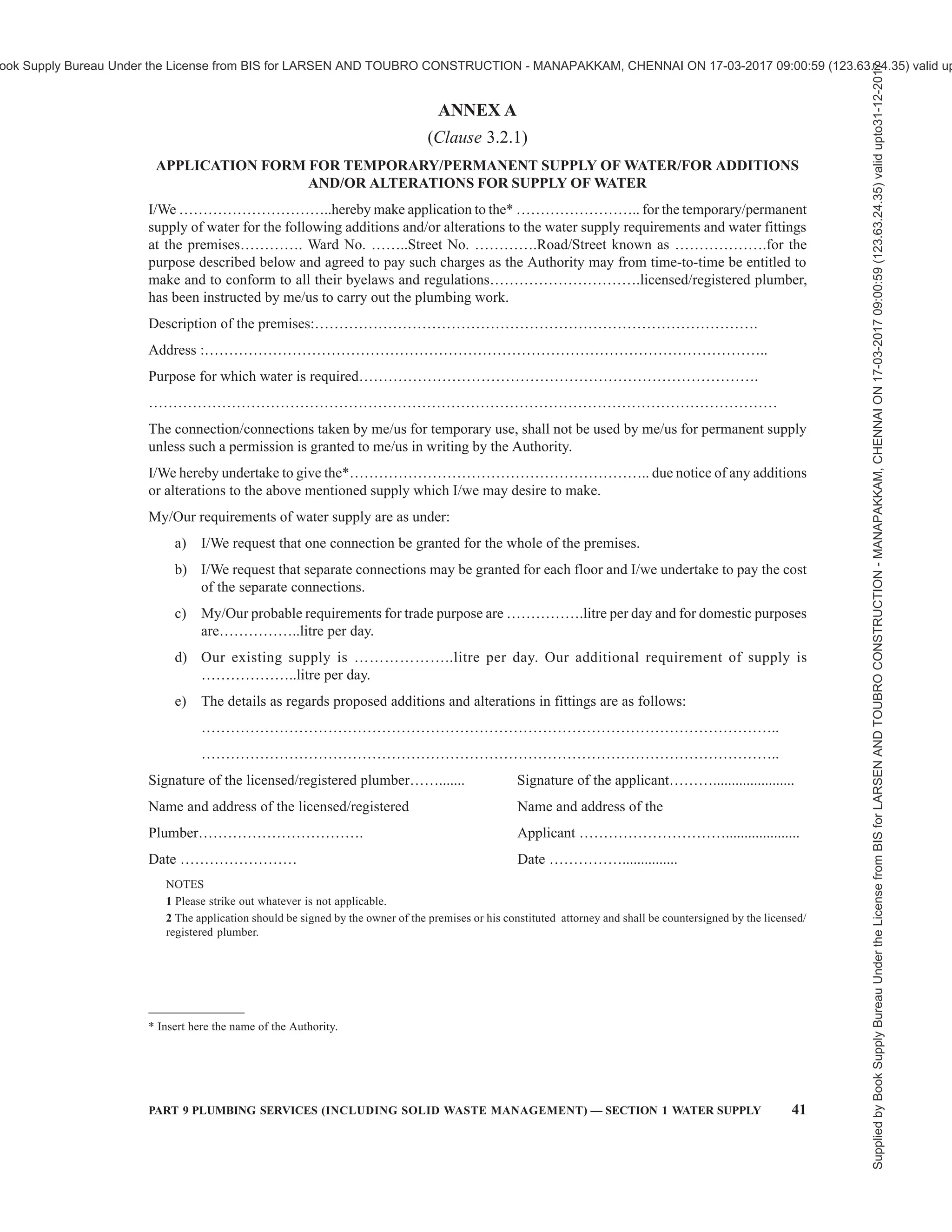

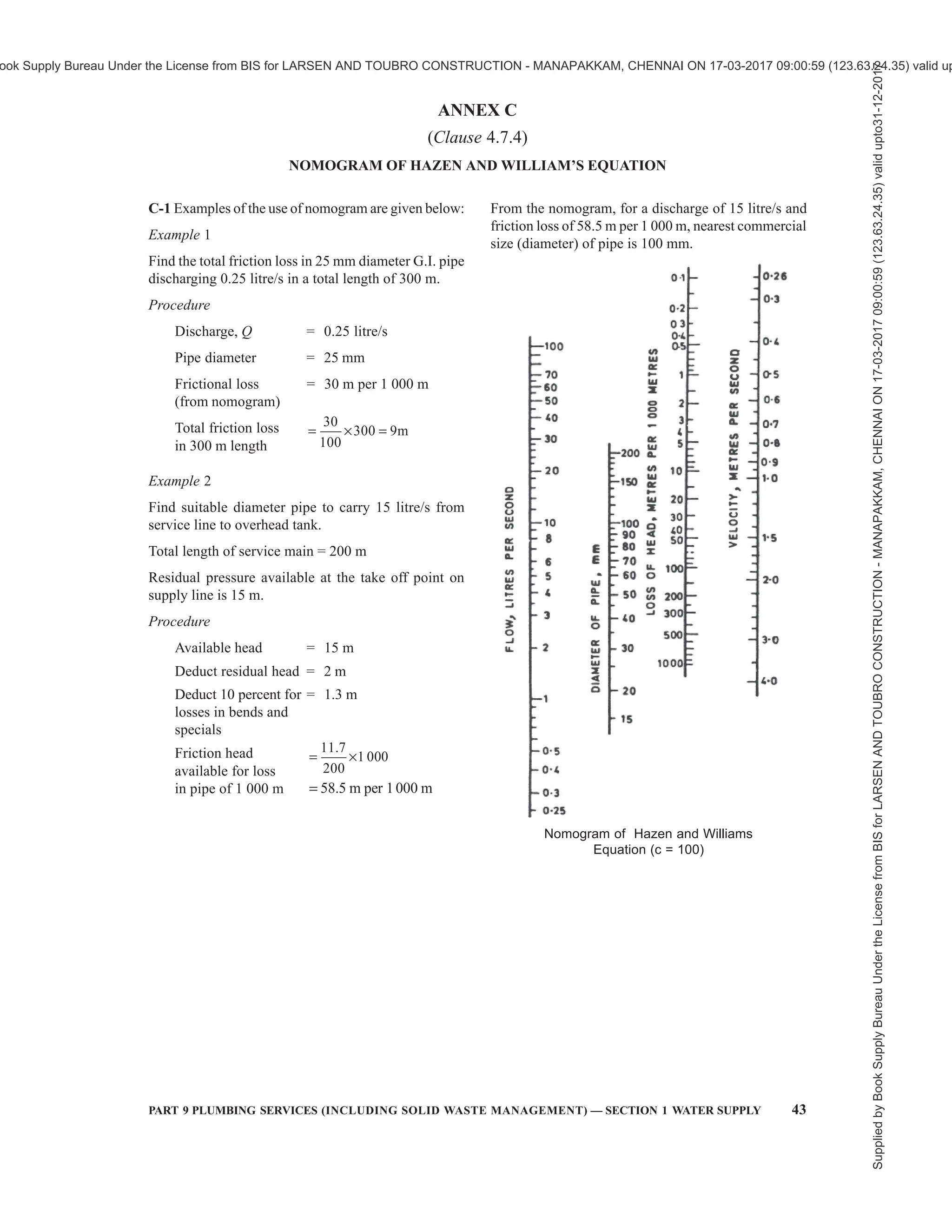

![PART 9 PLUMBING SERVICES (INCLUDING SOLID WASTE MANAGEMENT) — 5
SECTION 2 DRAINAGE AND SANITATION
2.8 Bed Pan Washer — A washer which is to be used
for disposing human waste and sterilizing the Bed Pan
for reuse. Bed pan washer requires water connection
and electrical heating arrangement. This is to be
considered as soil appliance.
2.9 Benching — Sloping surfaces constructed on either
side of channels at the base of a manhole or inspection
chamber for the purpose of confining the flow of
sewage, avoiding the accumulation of deposits and
providing a safe working platform.
2.10 Branch
a) Special form of sewer pipe used for making
connections to a sewer or water main. The
various types are called ‘T’, ‘Y’, ‘T-Y’, double
Y and V branches, according to their
respective shapes.
b) Any part of a piping system other than a main
or stack.
2.11 Branch Soil Pipe (BSP) — A pipe connecting
one or more soil appliances to the main soil pipe.
2.12 Branch Soil Waste Pipe (BSWP) — A pipe
connecting one or more soil and/or waste appliances
to the main soil waste pipe (one pipe system).
2.13 Branch Vent Pipe (BVP) — A pipe, one end of
which is connected to the system adjacent to the trap
of an appliance and the other to a main vent pipe or a
drain-vent pipe. It is fitted to prevent loss of water
seal from a trap owing to partial vacuum, back-
pressure, or surging caused by air movement within
the pipe system. It also provides ventilation for the
branch waste pipe.
2.14 Branch Waste Pipe (BWP) — A pipe
connecting one or more waste appliances to the main
waste pipe.
2.15 Building Drain-Combined — A building drain
which conveys both sewage and storm water or other
drainage.
2.16 Building Drain-Sanitary — A building drain
which conveys sewage and sullage only.
2.17 Building Drain-Storm — A building drain which
conveys storm water or other drainage but no sewage
or sullage.
1 SCOPE
1.1 This Code (Part 9/Section 2) covers the design,
layout, construction and maintenance of drains for foul
water, surface water, subsoil water and sewage together
with all ancillary works, such as connections, manholes
and inspection chambers used within the building and
from building to the connection to a public sewer,
private sewer, individual sewage-disposal system, cess-
pool, soakaway or to other approved point of disposal/
treatment work.
NOTE — A sanitary drainage system consists of a building
sewer, a building drain, a soil and/or waste stack, horizontal
branches or fixture drain, and vents. The sanitary drainage of a
large building may have a number of primary and secondary
branches, and several soil and/or waste stacks, each of them in
turn may have a number of horizontal branches.
2 TERMINOLOGY
For the purpose of this Section, the following definitions
shall apply in addition to the definitions given in
accepted standards [9-2(1)].
2.1 Air Admittance Valve — One way valves designed
to allow air to enter drainage system when negative
pressure develops in the system. The purpose is to
provide a method of allowing air to enter the drainage
system for prevention of siphonage of traps.
2.2 Air Break — Physical separation which may be a
low inlet into the indirect waste receptor from the fixture
or device indirectly connected.
2.3 Air Gap, Drainage — Unobstructed vertical
distance through the free atmosphere between the
lowest opening from any pipe, plumbing fixture or
appurtenance conveying waste to flood level of the
receptor.
2.4 Back Up — A condition where the waste water
may flow back into another fixture or compartment but
not back into the potable water system.
2.5 Back Water Valve — Device installed in a drainage
system to prevent reverse flow.
2.6 Bath Room Group — Group of fixtures consisting
of water closet, lavatories bath tub or shower and other
fittings with a floor drain located together.
2.7 Battery of Fixtures — Any group of two or more
similar adjacent fixtures which discharge into a
common horizontal waste or soil pipe.
NATIONAL BUILDING CODE OF INDIA
PART 9 PLUMBING SERVICES
(INCLUDING SOLID WASTE MANAGEMENT)
Section 2 Drainage and Sanitation
Supplied
by
Book
Supply
Bureau
Under
the
License
from
BIS
for
LARSEN
AND
TOUBRO
CONSTRUCTION
-
MANAPAKKAM,
CHENNAI
ON
17-03-2017
09:00:59
(123.63.24.35)
valid
upto31-12-2017
ook Supply Bureau Under the License from BIS for LARSEN AND TOUBRO CONSTRUCTION - MANAPAKKAM, CHENNAI ON 17-03-2017 09:00:59 (123.63.24.35) valid up](https://image.slidesharecdn.com/nationalbuildingcode-240401165105-f4e9283c/75/NBC-National-Building-Code-volume-1-and-2-53-2048.jpg)

![PART 9 PLUMBING SERVICES (INCLUDING SOLID WASTE MANAGEMENT) — 7
SECTION 2 DRAINAGE AND SANITATION
2.43 French Drain or Rubble Drain — A shallow
trench filled with coarse rubble, clinker, or similar
material with or without field drain pipes.
2.44 Frost Line — The line joining the points of
greatest depths below ground level up to which the
moisture in the soil freezes.
2.45 Grease Interceptor (or Grease Trap) — A
chamber, on the line of a drain or waste pipe, for
preventing grease from passing into the drainage
system. It reduces non-petroleum fats, oils and grease
in effluent by separation and volume reduction to
improve sewage treatment efficiency.
As it is used to intercept fats, oils and grease (FOG)
from a waste water discharge, it is also known as FOG
interceptor.
2.46 Gully Chamber — The chamber built of masonry
round a gully trap for housing the same.
2.47 Gully Trap — A trap provided in a drainage
system with a water seal fixed in a suitable position to
collect waste water from the scullery, kitchen sink, wash
basins, baths and rainwater pipes.
2.48 High Altitudes — Elevations higher than 1 500 m
above mean sea level (MSL).
2.49 Highway Authority — The public body in which
is vested, or which is the owner of, a highway repairable
by the inhabitants collectively; otherwise the body or
persons responsible for the upkeep of the highway.
2.50 Horizontal Pipe — Any pipe of fitting which
makes an angle of more than 45° with the vertical.
2.51 Indirect Waste Pipe — The pipe that does not
connect directly with the drainage system, but conveys
liquid wastes by discharging into a plumbing fixture/
interceptor that is directly connected to the drainage
system.
2.52 Inlet Fittings — An arrangement of connecting
the internal waste branch pipe from wash basin, sinks
and shower drains to the main deep seal trap with the
help of hopper extension.
2.53 Inlet Hopper — A receptacle fitting for receiving
refuse from each floor and dropping it into the chute.
2.54 Insanitary — Condition that is contrary to sanitary
principles or is injurious to health.
2.55 Inspection Chamber — A water-tight chamber
constructed in any house-drainage system which takes
wastes from gully traps and disposes to manhole with
access for inspection and maintenance.
2.56 Interceptor — A device designed and installed
so as to separate and retain deleterious, hazardous or
undesirable matter from normal wastes and permit
normal sewage or liquid wastes to discharge into the
disposal terminal by gravity.
2.57 Interceptor Manhole or Interceptor
Chamber — A manhole incorporating an intercepting
trap and providing means of access thereto.
2.58 Invert — The lowest point of the internal surface
of a pipe or channel at any cross-section.
2.59 Junction Pipe — A pipe incorporating one or
more branches.
2.60 Lagging — Thermal insulation or pipes.
2.61 Licensed (or Registered) Plumber — A person
licensed (or registered) under the provisions of this Code.
2.62 Main Soil Pipe (MSP) — A pipe connecting one
or more branch soil pipes to the drain.
2.63 Main Soil and Waste Pipe (MSWP) — A pipe
connecting one or more branch soil and waste pipes to
the drain.
2.64 Main Vent Pipe (MVP) — A pipe which receives
a number of branch vent pipes.
2.65 Main Waste Pipe (MWP) — A pipe connecting
one or more branch waste pipes to the drain.
2.66 Manhole — An opening by which a man may
enter or leave a drain, a sewer or other closed structure
for inspection, cleaning and other maintenance
operations, fitted with suitable cover.
2.67 Manhole Chamber — A Chamber constructed
on a drain or sewer so as to provide access thereto for
inspection, testing or clearance of obstruction.
2.68 Offset — A pipe fitting used to connect two pipes
whose axes are parallel but not in line.
2.69 Pipe System — The system to be adopted will
depend on the type and planning of the building in which
it is to be installed and will be one of the following:
a) Single stack system (see Fig. 1) — The piping
system in which there is no trap ventilation
and the stack itself acts as vent through roof.
In this system care shall be taken for proper
sizing of the pipes and the trap arm distance,
specially the horizontal distance of sanitary
fixtures from the drainage stack and vertical
distance between connection of branches from
fixtures to drainage stack.
b) One pipe — Partially ventilated system
(see Fig. 2) — The piping system in which
soil and waste pipes are connected to a single
vertical stack [as explained in 2.69 (a)] with
additional vent pipe for ventilation of traps of
water closets. It is also sometimes known as
single stack — partially ventilated system.
Supplied
by
Book
Supply
Bureau
Under
the
License
from
BIS
for
LARSEN
AND
TOUBRO
CONSTRUCTION
-
MANAPAKKAM,
CHENNAI
ON
17-03-2017
09:00:59
(123.63.24.35)
valid
upto31-12-2017
ook Supply Bureau Under the License from BIS for LARSEN AND TOUBRO CONSTRUCTION - MANAPAKKAM, CHENNAI ON 17-03-2017 09:00:59 (123.63.24.35) valid up](https://image.slidesharecdn.com/nationalbuildingcode-240401165105-f4e9283c/75/NBC-National-Building-Code-volume-1-and-2-55-2048.jpg)


![PART 9 PLUMBING SERVICES (INCLUDING SOLID WASTE MANAGEMENT) — 15
SECTION 2 DRAINAGE AND SANITATION
a) Every floor of the building in which the pipes
or drains are to be used;
b) The position, forms, level and arrangement of
the various parts of such building, including
the roof thereof;
c) All new drains as proposed with their sizes
and gradients;
d) Invert levels of the proposed drains with
corresponding ground levels;
e) The position of every manhole, gully, soil and
waste pipe, vent pipe, rainwater pipe, water
closet, urinal, latrine, bath, lavatory, sink, trap
or other appliances in the premises proposed
to be connected to any drain and the following
colours are recommended for indicating
sewers, waste water pipes, rainwater pipes an
existing work:
Description of Work Colour
Sewers Red
Waste water pipes and Blue
rainwater pipes
Existing work Black
f) The position of refuse chute, inlet hopper and
collection chamber.
3.2.3.1 In the case of an alteration or addition to an
existing building, this clause shall be deemed to be
satisfied if the plans as furnished convey sufficient
information for the proposals to be readily identified
with previous sanctioned plans and provided the
locations of tanks and other fittings are consistent with
the structural safety of the building.
3.2.3.2 The plans for the building drainage shall in every
case be accompanied by specifications for the various
items of work involved. This information shall be
supplied in the prescribed form given in Annex B.
3.2.4 In respect of open drains, cross-sectional details
shall be prepared to a scale not smaller than 1 in 50
showing the ground and invert levels and any
arrangement already existing or proposed for the
inclusion of any or exclusion of all storm water from
the sewers.
3.2.5 Completion Certificate
At the completion of the plumbing installation work,
the licensed/registered plumber shall give a completion
certificate in the prescribed form, which is given in
Annex C.
3.3 Licensing/Registration of Plumbers
3.3.1 Execution of Work
The work which is required to be carried out under the
provisions of this section, shall be executed only by a
licensed/registered plumber under the control of the
Authority and shall be responsible to carry out all lawful
directions given by the Authority. No individual shall
engage in the business of plumbing unless so licensed/
registered under the provisions of this Section.
3.3.1.1 No individual, firm, partnership or corporation
shall engage in the business of installing, repairing or
altering plumbing unless the plumbing work performed
in the course of such business is under the direct
supervision of a licensed/registered plumber from
approved Authority.
3.3.2 Examination and Certification
The Authority shall establish standards and procedure
for the qualification, examination and licensing/
registration of plumbers and shall issue licences to such
persons who meet the qualifications thereof and
successfully pass the examination.
3.3.3 For guidelines for registration of plumbers
including the minimum standards for qualifications for
the grant of licences, reference may be made to good
practice [9-2(2)]. The Authority may also utilize the
services of the certified plumbers who are certified for
the required skill level under the appropriate scheme
of the Government.
4 DRAINAGE AND SANITATION
4.1 Types of Sanitary Appliances
4.1.1 Soil Appliances
4.1.1.1 Water closet
It shall essentially consist of a closet consisting of a
bowl to receive excretory matter, trap and a flushing
apparatus. It is recommended to provide ablution tap
adjacent to the water closet, preferably on right hand
side wall. The various types/style of water closets may
be:
a) Squatting Indian type water closet,
b) Washdown type water closet,
c) Siphonic washdown type water closet, and
d) Universal or Anglo-Indian water closet.
4.1.1.2 Bidet
Bidet is an ablution appliance for cleansing excretory
organs with water for personnel hygiene. It may be
pedestal type or wall hung with a shallow bowl. Hot
and cold water supplied through a mixer is discharged
from a spray installed over the rim of the appliance.
The bidet outlet should essentially connect to soil pipe
in a system.
Supplied
by
Book
Supply
Bureau
Under
the
License
from
BIS
for
LARSEN
AND
TOUBRO
CONSTRUCTION
-
MANAPAKKAM,
CHENNAI
ON
17-03-2017
09:00:59
(123.63.24.35)
valid
upto31-12-2017
ook Supply Bureau Under the License from BIS for LARSEN AND TOUBRO CONSTRUCTION - MANAPAKKAM, CHENNAI ON 17-03-2017 09:00:59 (123.63.24.35) valid up](https://image.slidesharecdn.com/nationalbuildingcode-240401165105-f4e9283c/75/NBC-National-Building-Code-volume-1-and-2-63-2048.jpg)
![16 NATIONAL BUILDING CODE OF INDIA 2016
4.1.1.3 Urinal
It is a soil appliance for urination and is connected to
soil pipe after a suitable trap. Urinal should have
adequate provision of flushing apparatus. The various
types/style of urinal may be:
a) Bowl type urinal: flat back or angle back.
b) Slab (single) type urinal.
c) Stall (single) type urinal.
d) Squatting plate type urinal.
e) Syphon jet urinal with integral trap.
f) Water less (non-water) urinal
4.1.1.4 Slop sink
Slop sink is a large sink, generally of square shape. the
appliance is used in hospitals and is installed in the
dirty utility room, sluice room and similar locations
for disposal of excreta and other foul waste and for
washing bed pans and urine bottles/pans. It is provided
with a flushing mechanism. It is also provided in
Janitor’s closet where it is used for cleaning the
housekeeping mops, etc.
4.1.1.5 Bed pan sink
Bed pan sink, also known as bedpan washer and
disinfector, is a part of medical equipment inventory
which is used to clean manually or automatically, the
hospital bedpans, urine bottles and other containers
used for collecting body fluids. It is provided in dirty
utility room, sluice room, similar locations for disposal
of excreta and other foul waste and for washing bed
pans, urine bottles/pans. It is a soil appliance and is
connected to soil pipe after a suitable trap. In manual
models, it has a flushing arrangement.
Provision for installing a bedpan washer and
disinfector should be made in all intensive care units
in hospitals.
4.1.2 Waste Appliances
4.1.2.1 Wash basin
It is of one-piece construction having a combined
overflow and preferably should have soap holding
recess or recesses that should properly drain into the
bowl. Each basin shall have circular waste hole
through which the liquid content of the basin shall
drain.
4.1.2.2 Wash-trough
It is a linear trough for simultaneous use by number of
persons.
4.1.2.3 Sink
It is used in kitchen and laboratory for the purpose of
cleaning utensils/ apparatus and also serve the purpose
of providing water for general usage. The sink may be
made with or without overflow arrangement. The sink
shall be of one-piece construction including combined
over flow, where provided. The sink shall have a
circular waste hole into which the interiors of the sink
shall drain.
4.1.2.4 Bath tub
Bath tub may be of enameled steel, cast iron, gel-coated,
glass fibre reinforced plastic or may be cast in-situ. It
shall be stable, comfortable, easy to get in and out, water
tight, with anti-skid base, and easy to install and
maintain. The bath tub shall be fitted with overflow
and waste pipe of nominal diameter of not less than
32 mm and 40 mm, respectively.
4.1.2.5 Drinking fountain
It is a bowl fitted with a push button tap and a water
bubbler or a tap with a swan neck outlet fitting. It has
a waste fitting, a trap and is connected to the waste
pipe.
4.1.3 The requirements of various soil appliances and
waste appliances shall be in accordance with accepted
standards [9-2(3)].
4.2 Drainage and Sanitation Requirements
4.2.1 General
There should be at least one water tap and arrangement
for drainage in the vicinity of each water closet or group
of water closet in all the buildings.
4.2.2 Each dwelling unit on premises (abutting on a
sewer or with a private sewage disposal system) shall
have at least one water closet, one kitchen wash place
or a sink, and one bathing place or shower to meet
the basic requirements of sanitation and personal
hygiene.
In case of a group housing, the requirements relating
to toilet or sanitary room and kitchen as given in 13
and B-9 of Part 3 ‘Development Control Rules and
General Building Requirements’ of the Code shall also
be complied with.
4.2.3 All other structures for human occupancy or use
on premises (abutting on a sewer or with a private
sewage disposal system) shall have adequate sanitary
facilities, but in no case less than one water closet and
one other fixture for cleaning purposes.
Supplied
by
Book
Supply
Bureau
Under
the
License
from
BIS
for
LARSEN
AND
TOUBRO
CONSTRUCTION
-
MANAPAKKAM,
CHENNAI
ON
17-03-2017
09:00:59
(123.63.24.35)
valid
upto31-12-2017
ook Supply Bureau Under the License from BIS for LARSEN AND TOUBRO CONSTRUCTION - MANAPAKKAM, CHENNAI ON 17-03-2017 09:00:59 (123.63.24.35) valid up](https://image.slidesharecdn.com/nationalbuildingcode-240401165105-f4e9283c/75/NBC-National-Building-Code-volume-1-and-2-64-2048.jpg)

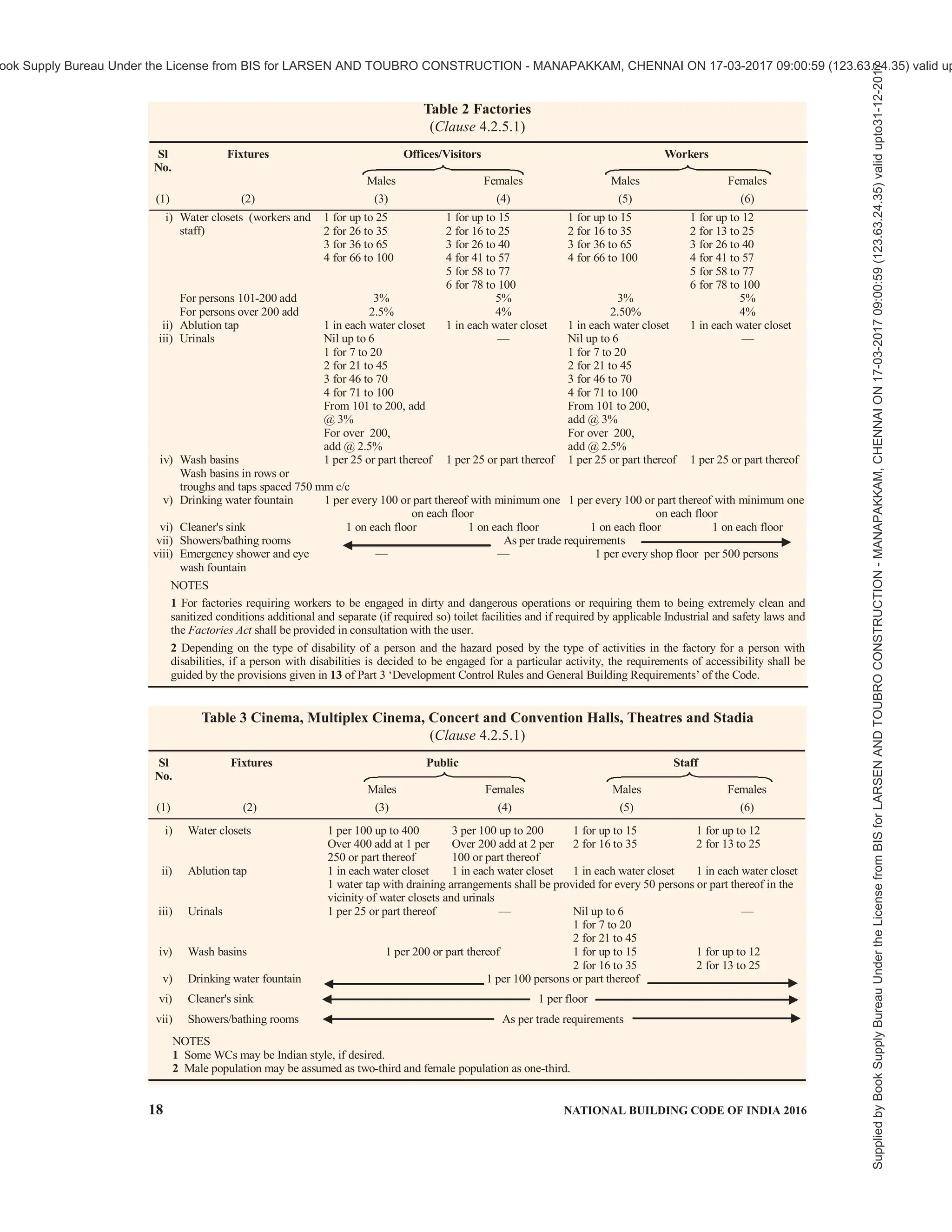

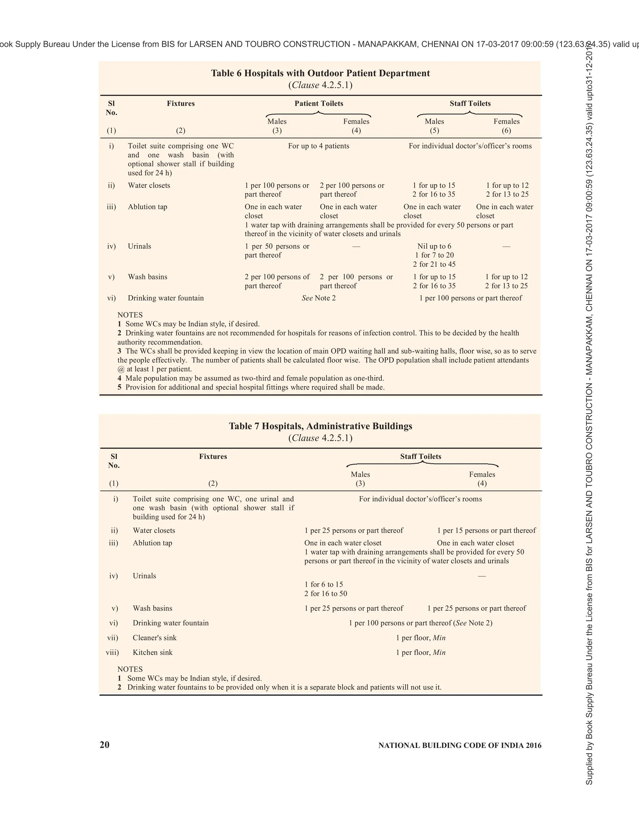


![PART 9 PLUMBING SERVICES (INCLUDING SOLID WASTE MANAGEMENT) — 25
SECTION 2 DRAINAGE AND SANITATION
installation suited to the need of a specific
building. For example, schools should be
provided with toilet facilities on each floor.
Similarly, toilet facilities shall be provided for
temporary workmen employed in any
establishment according to the needs; and in
any case one WC and one wash basin shall be
provided.
f) All buildings used for human habitation for
dwelling, work, occupation, medical care or
any purpose detailed in the various tables,
abutting a public sewer or a private sewage
disposal system, shall be provided with
minimum sanitary facilities as per the schedule
in the tables. In case the disposal facilities are
not available, they shall be provided as a part
of the building design for ensuring high
standards of sanitary conditions in accordance
with this section.
g) Workplaces where crèches are provided, they
shall be provided with one WC for 10 persons
or part thereof, one wash basin for 15 persons
or part thereof, one kitchen sink with floor trap
for preparing food/milk preparations. The sink
provided shall be with a drinking water tap.
h) In all types of buildings, individual toilets and
pantry should be provided for executives, and
for meeting/seminar/conference rooms, etc, as
per the user requirement.
j) Where food is consumed indoors, water
stations may be provided in place of drinking
water fountains.
4.3 Materials, Fittings and Appliances
4.3.1 Standards for Materials, Fittings and Sanitary
Appliances
All materials, fittings and sanitary appliances shall
conform to Part 5 ‘Building Materials’ of the Code.
4.3.2 Choice of Material for Pipes
4.3.2.1 Salt glazed stoneware pipe
For all sewers and drains in all soils, except where
supports are required as in made-up ground, glazed
stoneware pipe shall be used as far as possible in
preference to other types of pipes. These pipes are
particularly suitable where acid effluents or acid subsoil
conditions are likely to be encountered. Salt glazed
stoneware pipes shall conform to accepted standards
[9-2(4)].
4.3.2.2 Cement concrete pipes
When properly ventilated, cement concrete pipes with
spigot and socket or collar joints present an alternative
to glazed stoneware sewers of over 150 mm diameter.
These shall not be used to carry acid effluents or sewage
under conditions favourable for the production of
hydrogen sulphide and shall not be laid in those subsoils
that are likely to affect adversely the quality or strength
of concrete. Where these pipes are employed for
conveying liquid containing sulphates, the pipes used
shall be manufactured using sulphate resisting Portland
cement. Owing to the longer lengths of pipes available,
the joints would be lesser in the case of cements
concrete pipes. These pipes may be used for surface
water drains in all diameters. Cement concrete pipes
shall conform to accepted standards [9-2(5)].
4.3.2.3 Cast iron pipes
4.3.2.3.1 These pipes shall be used in the following
situation:
a) In bed or unstable ground where soil
movement is expected;
b) In made-up or tipped ground;
c) To provide for increased strength where a
sewer is laid at insufficient depth, where it is
exposed or where it has to be carried on piers
or above ground;
d) Under buildings and where pipes are
suspended in basements and like situations;
e) In reaches where the velocity is more than
2.4 m/s; and
f) For crossings of watercourses.
NOTE — In difficult foundation condition such a in the case
of black cotton soil, the cast iron pipes shall be used only when
suitable supporting arrangements are made.
4.3.2.3.2 It shall be noted that cast iron pipes even when
given a protective paint are liable to severe external
corrosion in certain soils; among such soils are:
a) Soils permeated by peaty waters; and
b) Soils in which the subsoil contains appreciable
concentrations of sulphates. Local experiences
shall be ascertained before cast iron pipes are
used where corrosive soil conditions are
suspected. Where so used, suitable measures
for the protection of the pipes may be resorted
to as an adequate safeguard.
4.3.2.3.3 Cast iron pipes shall conform to accepted
standards [9-2(6)].
4.3.2.4 Asbestos cement pipes
Asbestos cement pipes are commonly used for house
drainage systems and they shall conform to accepted
standards [9-2(7)]. They are not recommended for
underground situations. However, asbestos cement
pressure pipes conforming to accepted standards
[9-2(7)] may be used in underground situations also,
provided they are not subject to heavy superimposed
Supplied
by
Book
Supply
Bureau
Under
the
License
from
BIS
for
LARSEN
AND
TOUBRO
CONSTRUCTION
-
MANAPAKKAM,
CHENNAI
ON
17-03-2017
09:00:59
(123.63.24.35)
valid
upto31-12-2017
ook Supply Bureau Under the License from BIS for LARSEN AND TOUBRO CONSTRUCTION - MANAPAKKAM, CHENNAI ON 17-03-2017 09:00:59 (123.63.24.35) valid up](https://image.slidesharecdn.com/nationalbuildingcode-240401165105-f4e9283c/75/NBC-National-Building-Code-volume-1-and-2-73-2048.jpg)
![26 NATIONAL BUILDING CODE OF INDIA 2016
loads. These shall not be used to carry acid effluents or
sewage under conditions favourable for the production
of hydrogen sulphide and shall not be laid in those
subsoils which are likely to affect adversely the quality
or strength of asbestos cement pipes. Where so desired,
the life of asbestos cement pipes may be increased by
lining inside of the pipe with suitable coatings like
epoxy/polyester resins, etc.
4.3.2.5 PVC pipes
Unplasticized PVC pipes may be used for drainage
purposes; however, where hot water discharge is
anticipated, the wall thickness shall be minimum 3 mm
irrespective of the size and flow load.
PVC and HDPE pipes shall conform to accepted
standards [9-2(8)].
NOTE — Where possible, high density polyethylene pipes
(HDPE) and PVC pipes may be used for drainage and sanitation
purposes, depending upon the suitability.
4.3.2.6 Corrugated pipes
These pipes (externally corrugated) are used for
sewerage and drainage applications. They are light
weight and have long life. The leakage and infiltration
at joints are less. The operational cost is low and can
easily withstand natural settlements without suffering
cracks or leakages. They consume fewer raw material
and have less carbon dioxide emission.
4.3.2.7 Low noise pipes
Waste water systems encompass the system of drainage
and pressure relief pipes within a building and terminate
0.5 m outside the external wall. Waste water systems
are based on the primary pressure-relief system in which
water and air-flow occurs in the same pipe. The waste
water system shall be separated from the roof drainage
system.
Noise is a variance in air pressure that spreads like a
wave. If quick changes in pressure occur between
20 and 20 000 times a second (frequency 20 Hz and
20 kHz), they are audible to humans. The loudness of
noise is determined by the amplitude of the wave, which
is measured in decibels (dB).
The main cause of noise in indoor drainage systems
(primarily focused on the downpipe) are the choice of
the pipe system, the bracket type and the design of
drainage system. Optimizing these factors will therefore
have the best influence on noise reduction.
4.3.2.8 Under slung pipes
In under slung plumbing, the toilet slab is built at the
same level as the slabs outside the toilet. Holes/core
cuts are punctured through the slab wherever pipes have
to pass through, and the plumbing is clamped to the
bottom of the slab. It is then concealed above a false
ceiling, which is accessible above the false ceiling for
routine maintenance. In this type of plumbing, any leaks
will drip onto the false ceiling which is easily detectable
thus allow quick maintenance without much damage
to the structure or occupied premises
4.4 Preliminary Data for Design
4.4.1 General
Before the drainage system for a building or group of
buildings is designed and constructed, accurate
information regarding the site conditions is essential.
This information may vary with the individual scheme
but shall, in general, be covered by the following:
a) Site plan (see 3.2.2).
b) Drainage plan (see 3.2.3).
c) Use — A description of the use for which the
building is intended and periods of occupation
in order that peak discharges may be
estimated;
d) Nature of waste — While dealing with sewage
from domestic premises, special problems
under this head may not arise; however, note
shall be taken of any possibility of trade
effluents being discharged into the pipes at a
future date;
e) Outlet connection — The availability of
sewers or other outlets;
f) Cover — The depth (below ground) of the
proposed sewers and drains and the nature and
weight of the traffic on the ground above them;
g) Subsoil condition
1) The approximate level of the subsoil
water, and any available records of flood
levels shall be ascertained, as also the
depth of the water table relative to all
sewer connections, unless it is known to
be considerably below the level of the
latter.
2) In the case of deep manholes, this
information will influence largely the type
of construction to be adopted. The
probable safe bearing capacity of the
subsoil at invert level may be ascertained
in the case of a deep manhole.
3) Where work of any magnitude is to be
undertaken, trial pits or boreholes shall
be put at intervals along the line of the
proposed sewer or drain and the data
therefrom tabulated, together with any
information available from previous
works carried out in the vicinity. In
general, the information derived from
Supplied
by
Book
Supply
Bureau
Under
the
License
from
BIS
for
LARSEN
AND
TOUBRO
CONSTRUCTION
-
MANAPAKKAM,
CHENNAI
ON
17-03-2017
09:00:59
(123.63.24.35)
valid
upto31-12-2017
ook Supply Bureau Under the License from BIS for LARSEN AND TOUBRO CONSTRUCTION - MANAPAKKAM, CHENNAI ON 17-03-2017 09:00:59 (123.63.24.35) valid up](https://image.slidesharecdn.com/nationalbuildingcode-240401165105-f4e9283c/75/NBC-National-Building-Code-volume-1-and-2-74-2048.jpg)

![28 NATIONAL BUILDING CODE OF INDIA 2016
disposed of by adequate treatment approved by the
Authority on the site. The effluent from the plant shall
be discharged after meeting the norms specified by the
statutory authority into a natural watercourse or on the
surface of the ground or disposed of subsoil dispersion
preferably draining to a suitable outlet channel.
4.4.3.2 In the case of dilution into a natural stream
course, the quality of the effluent shall conform and
the requirements of the Authority controlling the
prevention of pollution of streams.
4.4.3.3 In the case of subsoil dispersion, the
requirements of the Authority for water supply shall be
observed to avoid any possible pollution of local water
supplies or wells.
4.4.3.4 The general subsoil water level and the subsoil
conditions shall be ascertained, including the absorptive
capacity of the soil.
4.4.3.5 A subsoil dispersion is not desirable near a
building or in such positions that the ground below the
foundations is likely to be affected.
4.4.3.6 Where no other method of disposal is possible,
foul water may be diverted to cesspools and
arrangements made with the Authority for satisfactory
periodical removal and conveyance to a disposal works.
4.4.3.7 Under the separate system, drainage of the
building shall be done through septic tanks of different
sizes or by stabilization ponds or by any other treatment
methods such as extended aeration activated process,
sequential batch process, fluidized bio-reactors,
membrane bio-reactor, submerged aerobic fixed film,
rotating biological contactor, electrolyte process, etc,
as approved by the Authority.
For detailed information on the design and construction
of septic tanks and waste stabilization ponds, sewage
treatment plants reference may be made to good
practice [9-2(9)].
4.4.3.8 Bio-toilet (or eco-toilet)
It is useful in situations where no suitable water supply
or sewer system and sewage treatment plant is available
to capture the nutrients in human excreta.
The toilet is made of a structure, generally of
prefabricated type, above the ground, a bio-digester tank
below the ground and in case of sub-zero temperature
regions, a solar panel. Bio-toilet involves complete
sludge free disposal of human waste and eliminates need
for manual scavenging. It decomposes solid waste to
water and bio-gas. It is eco-friendly, hazard free,
requiring least maintenance and is capable of functioning
efficiently at sub-zero temperatures (see Fig. 5)
4.4.4 Disposal of Surface and Subsoil Waters
All information which may influence the choice of
methods of disposal of surface and/or subsoil waters
shall be obtained. In the absence of surface water
drainage system, and if practicable and permissible,
disposal into a natural water-course or soakaway may
be adopted. The location and flood levels of the water
course as also the requirements of the Authority
controlling the river or the waterway shall be
ascertained.
4.5 Planning and Design Considerations
4.5.1 Aim
The efficient disposal of foul and surface water from a
building is of great importance to public health and is
FIG. 5 BIO-TOILET OR ECO-TOILET
Supplied
by
Book
Supply
Bureau
Under
the
License
from
BIS
for
LARSEN
AND
TOUBRO
CONSTRUCTION
-
MANAPAKKAM,
CHENNAI
ON
17-03-2017
09:00:59
(123.63.24.35)
valid
upto31-12-2017
ook Supply Bureau Under the License from BIS for LARSEN AND TOUBRO CONSTRUCTION - MANAPAKKAM, CHENNAI ON 17-03-2017 09:00:59 (123.63.24.35) valid up](https://image.slidesharecdn.com/nationalbuildingcode-240401165105-f4e9283c/75/NBC-National-Building-Code-volume-1-and-2-76-2048.jpg)
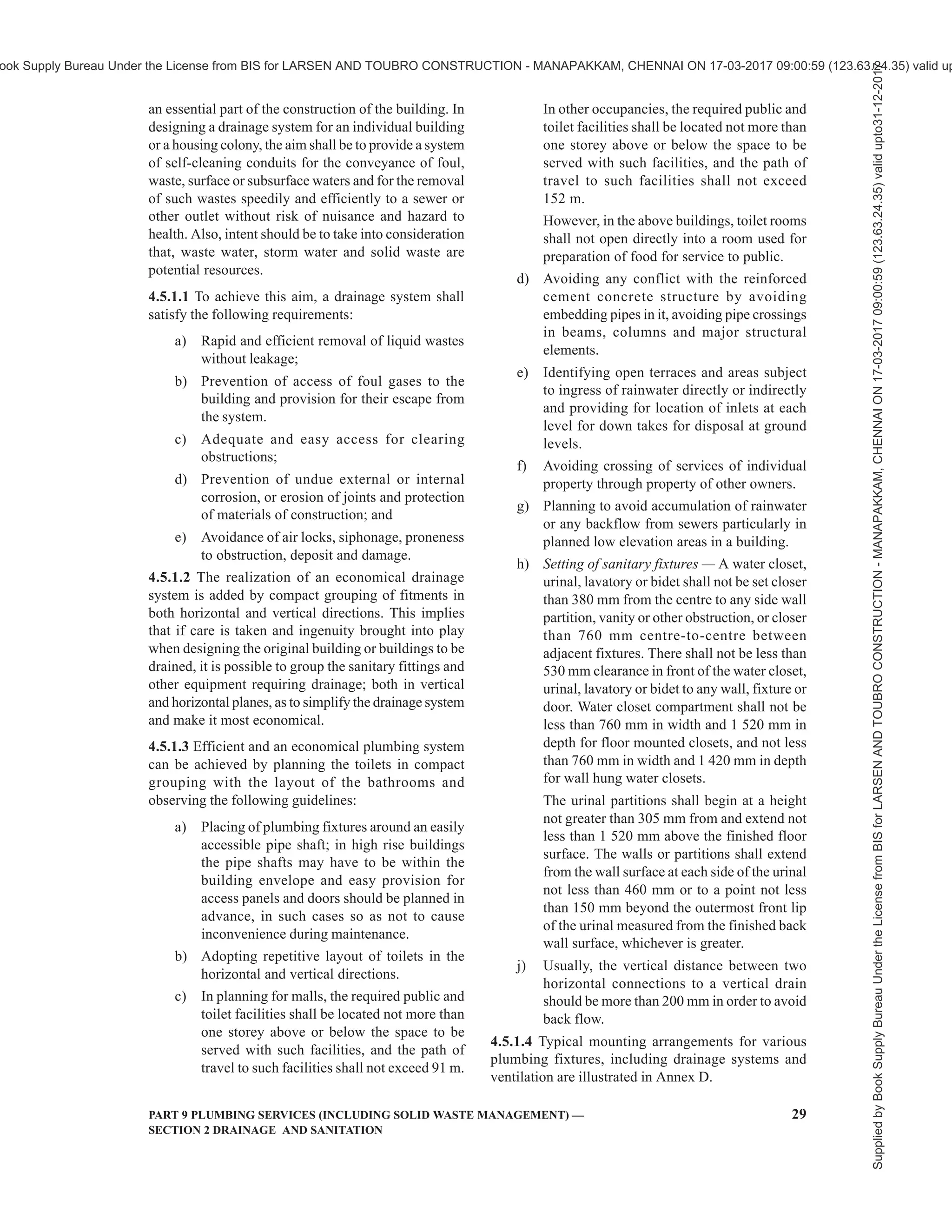
![30 NATIONAL BUILDING CODE OF INDIA 2016
4.5.2 Layout
4.5.2.1 General
Rainwater should preferably be dealt separately from
sewage and sullage. Sewage and sullage shall be
connected to sewers. However, storm water from the
courtyard may be connected to the sewer where it is
not possible to drain otherwise; after obtaining
permission of the Authority.
4.5.2.2 Additional requirements
The following requirements are suggested to be
considered in the design of drainage system:
a) The layout shall be as simple and direct as
practicable.
b) The pipes should be laid in straight lines, as
far as possible, in both vertical and horizontal
planes.
c) Anything that is likely to cause irregularity of
flow, such as abrupt changes of direction, shall
be avoided.
d) The pipes should be non-absorbent, durable,
smooth in bore and of adequate strength.
e) The pipes should be adequately supported
without restricting movement.
f) Drains should be well ventilated, to prevent
the accumulation of foul gases and fluctuation
of air pressure within the pipe, which could
lead to unsealing (siphoning) of gully or water
closet traps.
g) All the parts of the drainage system should be
accessible for feasibility of inspection and
practical maintenance.
h) No bends and junctions whatsoever shall be
permitted in sewers except at manholes and
inspection chambers.
j) Sewer drain shall be laid for self-cleaning
velocity of 0.75 m/s and generally should not
flow more than half-full.
k) Pipes crossing in walls and floors shall be
through mild steel sleeves of diameter leaving
an annular space of 5 mm around the outer
diameter of the pipe crossing the wall.
m) Pipes should not be laid close to building
foundation.
n) Pipes should not pass near large trees because
of possibility of damage by the roots.
p) Branch connections should be swept in the
direction of flow.
q) Sewer pipes should be at least 900 mm below
road and at least 600 mm below fields and
gardens.
r) Pipes should not pass under a building unless
absolutely necessary. Where it is necessary to
lay pipes under a building, the following
conditions shall be observed:
1) Pipes shall be centrifugally cast (spun)
iron pressure pipe as per good practice
[9-2(10)];
2) The pipe shall be laid in straight line and
at uniform gradient;
3) Means of access in form of manholes/
inspection chamber shall be provided at
each end, immediately outside the
building;
4) In case the pipe or any part of it is laid
above the natural surface of the ground,
it shall be laid on concrete supports, the
bottom of which goes at least 150 mm
below the ground surface.
NOTE — It is desirable that pipe/drains should
not be taken through a living room or kitchen and
shall preferably be taken under a staircase room
or passage.
s) Consideration shall be given to alternative
layouts so as to ensure that the most
economical and practical solution is
adopted. The possibility of alterations shall
be avoided by exercising due care and
forethought.
4.5.2.3 Protection against vermin and dirt
The installation of sanitary fittings shall not introduce
crevices which are not possible to inspect and clean
readily.
Pipes, if not embedded, shall be run well clear of the
wall. Holes through walls to lay pipes shall be made
good on both sides to prevent entry of insects. Materials
used for embedding pipes shall be rodent-proof.
Passage of rodents from room-to-room or from floor-
to-floor shall be prevented by suitable sealing. The
intermediate lengths of ducts and chases shall be
capable of easy inspection. Any unused drains, sewers,
etc, shall be demolished or filled in to keep them free
from rodents.
All pipe shafts shall be plastered before any pipes are
installed in the shaft. It is advisable to lay pipes on the
steel supports with adequate gap between plastered wall
and support structure. This will provide a smooth
surface and prevent location for survival of insects and
vermins.
4.5.2.4 Choice of plumbing system
4.5.2.4.1 In selecting one or more of the type of piping
systems, the building and the layout of toilets/fixtures,
relationship with other services, acceptability to the
Authority, and any special requirements of users, shall
be studied.
Supplied
by
Book
Supply
Bureau
Under
the
License
from
BIS
for
LARSEN
AND
TOUBRO
CONSTRUCTION
-
MANAPAKKAM,
CHENNAI
ON
17-03-2017
09:00:59
(123.63.24.35)
valid
upto31-12-2017
ook Supply Bureau Under the License from BIS for LARSEN AND TOUBRO CONSTRUCTION - MANAPAKKAM, CHENNAI ON 17-03-2017 09:00:59 (123.63.24.35) valid up](https://image.slidesharecdn.com/nationalbuildingcode-240401165105-f4e9283c/75/NBC-National-Building-Code-volume-1-and-2-78-2048.jpg)
![PART 9 PLUMBING SERVICES (INCLUDING SOLID WASTE MANAGEMENT) — 31
SECTION 2 DRAINAGE AND SANITATION
a) Single stack system [see 2.69 (a)]
1) The single stack system is ideal when the
toilet/fixture layouts are repetitive and
there is less space for pipes on the wall.
2) In any system so selected there should be
not more than two toilet connections per
floor.
3) The system requires minimum 100 mm
diameter stack for a maximum of 5 floors
in a building.
4) In this system, care shall be taken of the
horizontal distance of sanitary fixtures
from the drainage stack and vertical
distance between connections of branches
from fixtures to drainage stack.
5) All the safeguards for the use of this
system given in 4.5.2.4.2 shall be
complied with.
b) One pipe — partially ventilated system
[see 2.69 (b)]
The system and the applicable safeguards
under this system are the same as for single
stack system. The prime modification is to
vent the soil appliance(s).
c) One pipe — fully ventilated system
[see 2.69 (c)]
1) This system is suitable for buildings
where the toilet/fixture layouts and the
shafts are repetitive. It requires less shaft
space, and is economical.
2) Continuous flow of water in the pipe from
waste appliances makes it less prone to
blockage and makes the system more
efficient.
3) The system eliminates the need for a gully
trap which requires constant cleaning.
4) This system requires individual vent pipes
installed either in suspended ceiling or in
the wall above the floor level in the toilet,
provided construction details of the
building allow provision of vent pipes for
individual fixtures and routing of vent
pipes to remote shafts where main vent
stacks may have been located.
5) The system requires minimum 100 mm
diameter stack.
6) The system is ideal when the main pipes
run at the ceiling of the lowest floor or in
a service floor.
d) Two pipe system [see 2.69 (d)]
1) This system provides safety and
flexibility in layouts for larger toilets and
for buildings having higher requirement
of performance due to its height and type
of occupancy.
2) In large buildings and houses with open
ground and gardens, the sullage water
from the waste system can be suitably
treated and usefully utilized for gardening
and agriculture.
3) In larger and multi-storeyed buildings, the
sullage is treated within the building for
reuse as makeup water for cooling towers
for air conditioning system and is also
used for flushing water closets provided
it has absolutely no connection with any
water supply line, tank or system used for
domestic and drinking supply.
For detailed information regarding design and
installation of soil, waste and vent pipes, reference may
be made to good practice [9-2(11)].
4.5.2.4.2 Safeguards for single stack system
a) As far as practicable,the fixtures on a floor shall
be connected to stack in order of increasing
discharge rate in the downward direction.
b) The size of the vent pipe (terminating to the
outdoor) shall be same as the size of drainage
stack in the case of single stack system.
c) Water closets shall be connected to the stack
through a sanitary tee; the maximum horizontal
distance from the stack being 2 400 mm.
d) For fixtures other than water closets, the
maximum horizontal distance from the stack
shall be 3 500 mm.
e) The vertical distance between the waste
branch (from floor trap or from the individual
appliance) and the soil branch connection,
when soil pipe is connected to stack above
the waste pipe, shall be not less than 200 mm.
f) Depth of water seal traps from different
fixtures shall be as per 4.5.3.6.1.6.
g) Branches and stacks which receive
discharges from WC pans should not be less
than 100 mm, except where the outlet from
the siphonic water closet is 80 mm, in which
case a branch pipe of 80 mm may be used.
For outlet of floor traps 75 mm dia pipes may
be used.
h) The horizontalbranchdistancefor fixturesfrom
stack, bend(s) at the foot of stack to avoid back
pressure as well as vertical distance between
the lowest connection and the invert of drain
shall be as per good practice [9-2(11)].
j) For tall buildings, ground floor appliances are
recommended to be connected directly to
manhole/inspection chamber.
Supplied
by
Book
Supply
Bureau
Under
the
License
from
BIS
for
LARSEN
AND
TOUBRO
CONSTRUCTION
-
MANAPAKKAM,
CHENNAI
ON
17-03-2017
09:00:59
(123.63.24.35)
valid
upto31-12-2017
ook Supply Bureau Under the License from BIS for LARSEN AND TOUBRO CONSTRUCTION - MANAPAKKAM, CHENNAI ON 17-03-2017 09:00:59 (123.63.24.35) valid up](https://image.slidesharecdn.com/nationalbuildingcode-240401165105-f4e9283c/75/NBC-National-Building-Code-volume-1-and-2-79-2048.jpg)
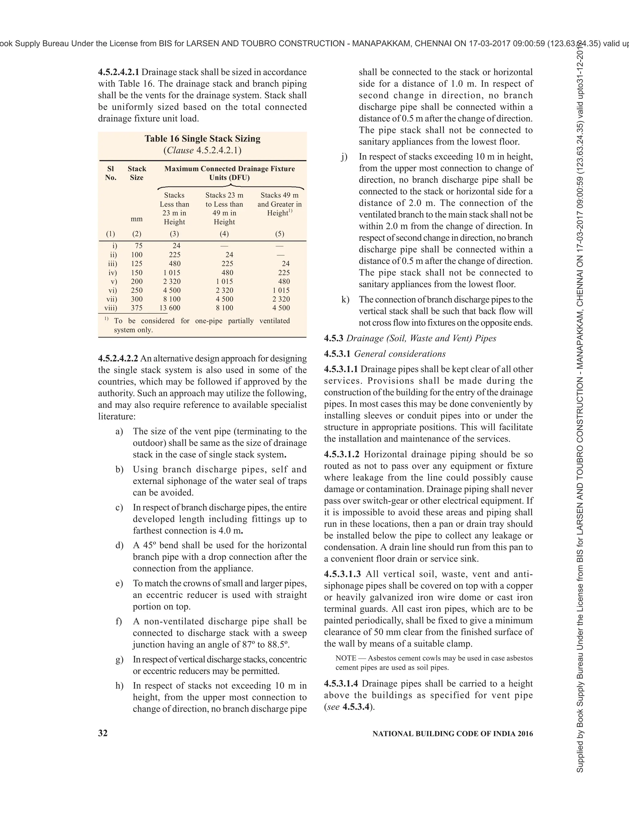

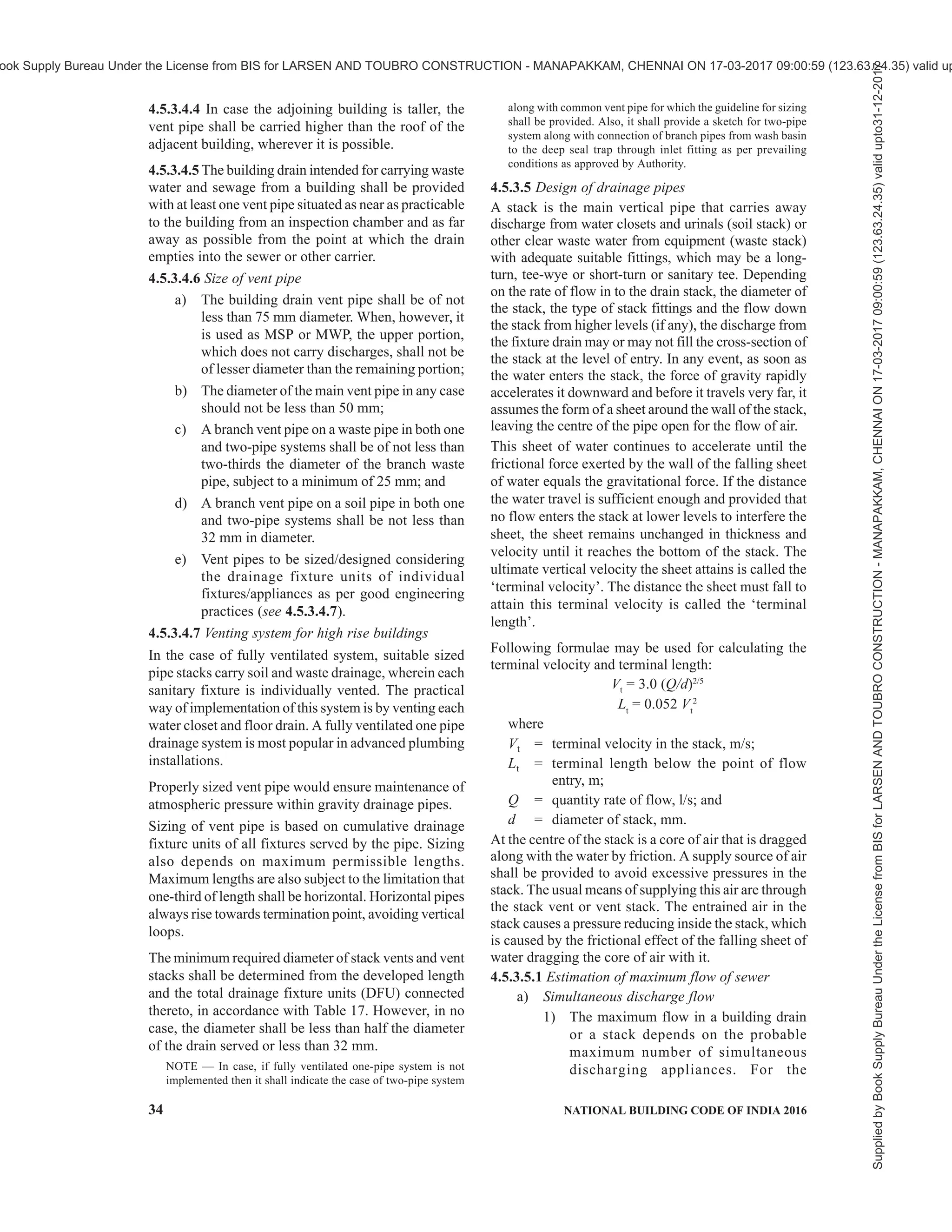


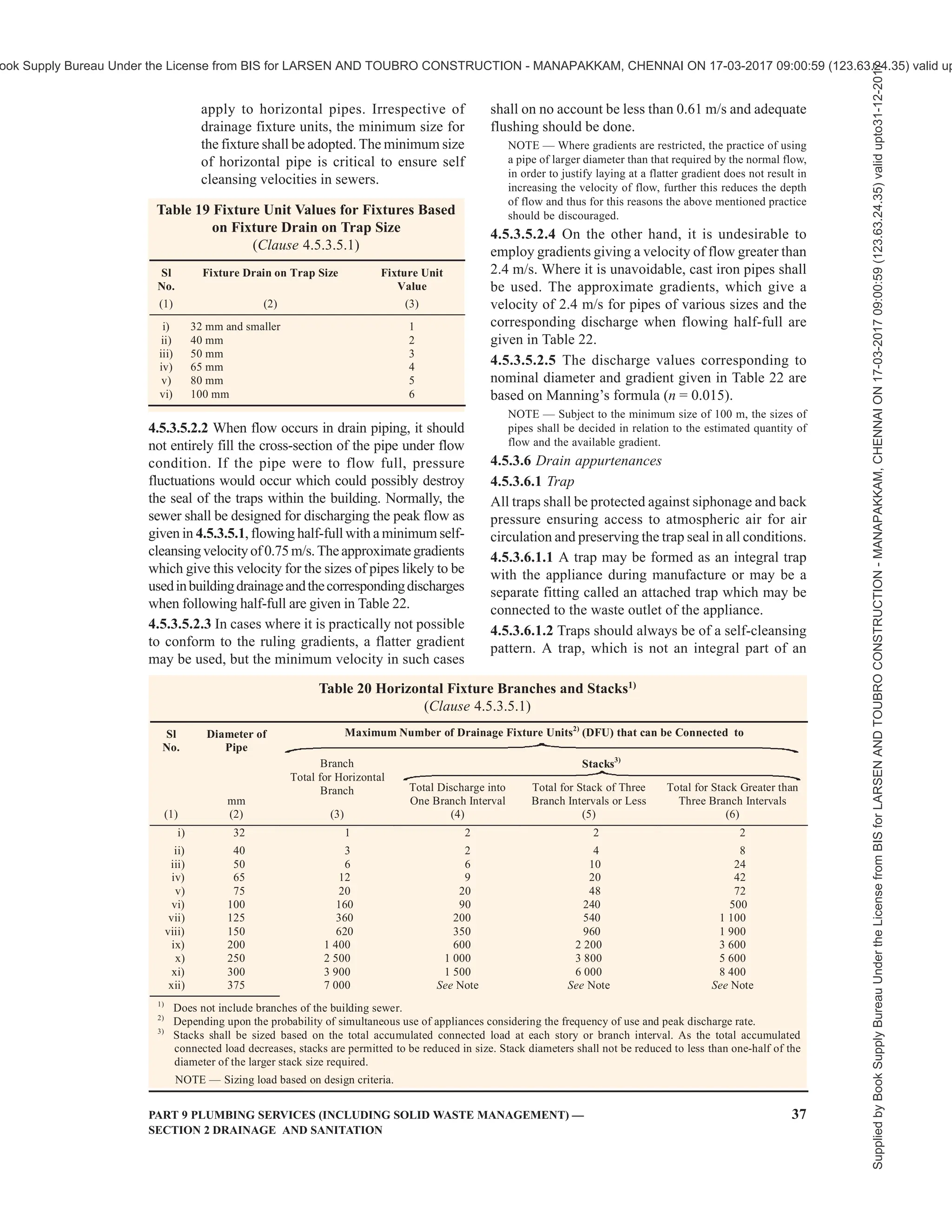
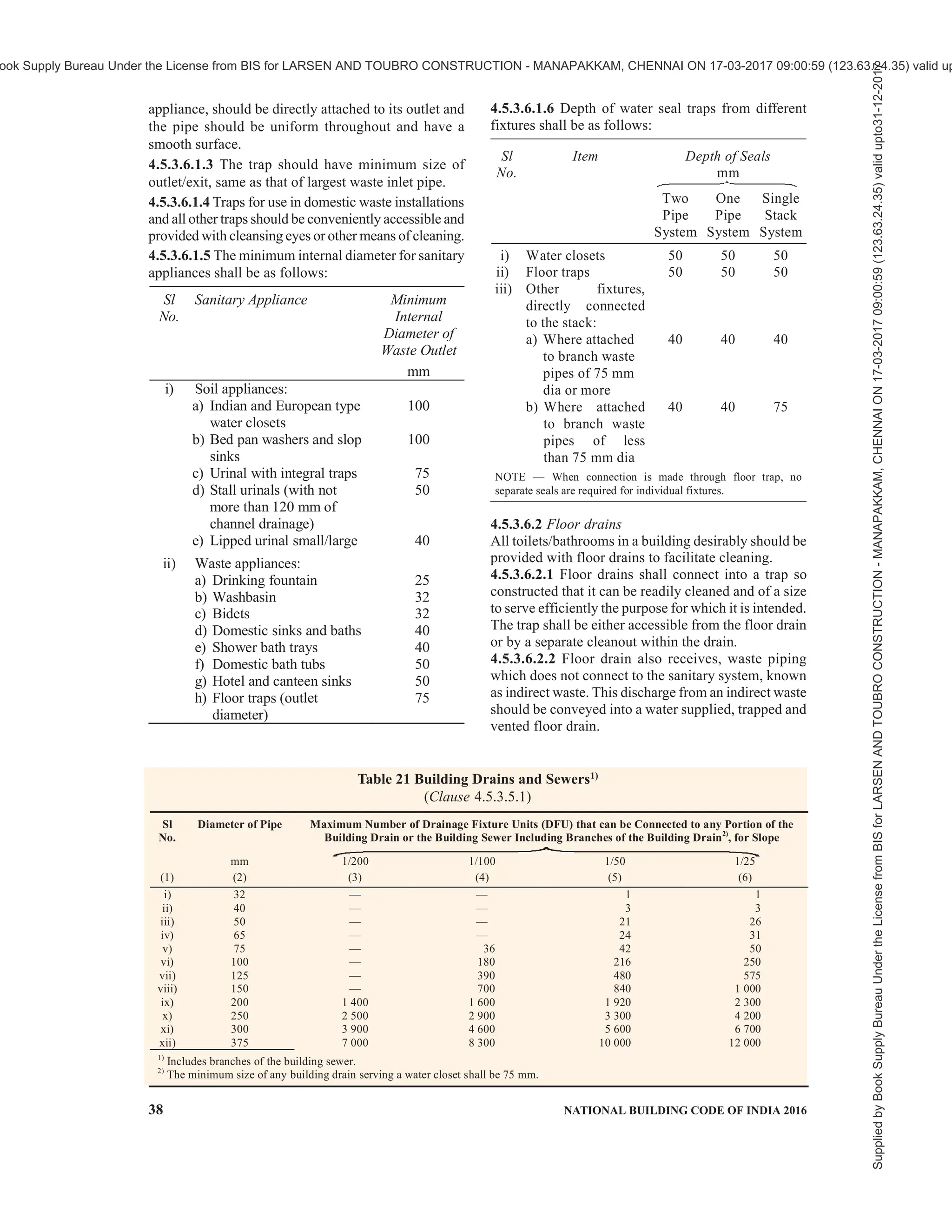
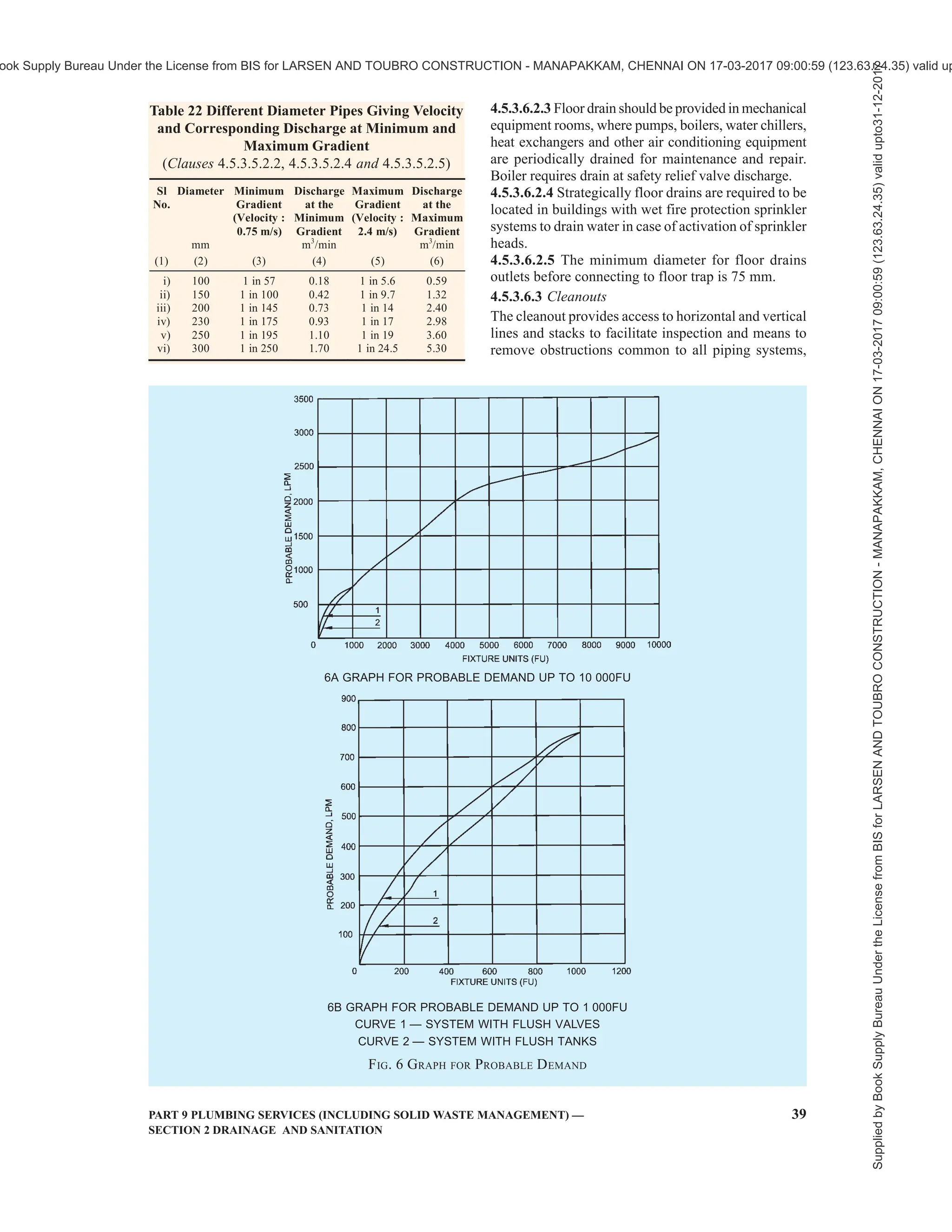

![42 NATIONAL BUILDING CODE OF INDIA 2016
sources shall be made to the building drainage system
indirectly through a trap. It should be ensured in
advance that the building drain or a sump with a pump
has the capacity to receive to rate of flow. In case the
capacity is less the rate of discharge from the appliances
should be regulated to meet the capacity of the disposal.
Under no circumstances shall any waste water described
above shall be disposed of in any storm water drains.
4.5.10 Manholes
4.5.10.1 General
A manhole or inspection chamber shall be capable of
sustaining the loads which may be imposed on it,
exclude subsoil water and be water tight. The size of
the chamber should be sufficient to permit ready access
to the drain or sewer for inspection, cleaning and
rodding and should have a removable cover of adequate
strength, constructed of suitable and durable material.
Where the depth of the chamber so requires, access
rungs, step irons, ladders or other means should be
provided to ensure safe access to the level of the drain
or sewer. If the chamber contains an open channel,
benching should be provided having a smooth finish
and formed so as to allow the foul matter to flow
towards the pipe and also ensure a safe foothold.
No manhole or inspection chamber shall be permitted
inside a building or in any passage therein. The
minimum depth of the manhole shall not be less than
800 mm to facilitate gully trap connection. Further,
ventilating covers shall not be used for domestic drains.
At every change of alignment, gradient or diameter of
a drain, there shall be a manhole or inspection chamber.
Bends and junctions in the drains shall be grouped
together in manholes as far as possible.
Alternative materials of manholes using RCC rings and
PVC in sewer lines are being used in some sites. These
may be considered subject to ensuring their proper
design, keeping in view the lateral and vertical loads at
the place of installation.
The holes over the surfaces of covers/gratings of
various manholes, gullys and other chambers/drains
shall comply with the requirements given in 13 of Part 3
‘Development Control Rules and General Building
Requirements’ of the Code.
4.5.10.2 Spacing of manholes
The spacing of manholes for a given pipe size should
be as follows:
Sl
No.
Pipe Diameter
mm
Spacing of Manhole
m
i) Up to 300 45
ii) 301 to 500 75
iii) 501 to 900 90
iv) Beyond 900 Spacing shall depend
upon local condition and
shall be gotten approved
by the Authority
Where the diameter of a drain is increased, the crown
of the pipes shall be fixed at the same level and the
necessary slope given in the invert of the manhole
chamber. In exceptional cases and where unavoidable,
the crown of the branch sewer may be fixed at a lower
level, but in such cases the peak flow level of the two
sewers shall be kept the same.
4.5.10.3 Size of manhole
The manhole or chamber shall be of such size as will
allow necessary examination or clearance of drains. The
size of shall be adjusted to take into account any
increase in the number of entries into the chamber.
4.5.10.3.1 Manholes may be rectangular, arch or circular
type. The minimum internal size of manholes, chambers
(between faces of masonry) shall be as follows:
a) Rectangular manholes:
1) For depths less than 900 mm ×
0.90 m 800 mm
2) For depths from 0.90 m 1 200 mm ×
and up to 2.5 m 900 mm
NOTE — For depths upto 0.60 m, 600 mm × 600 mm manhole
may be used.
b) Arch type manholes:
For depths of 2.5 m and 1 400 mm ×
above 900 mm
NOTE — The width of manhole chamber shall be suitably
increased more than 900 mm on bends, junctions or pipes with
diameter greater than 450 mm so that benching width in either
side of channel is minimum 200 mm.
c) Circular manholes:
1) For depths above 0.90 m 900 mm
and up to 1.65 m diameter
2) For depths above 1.65 m 1 200 mm
and up to 2.30 m diameter
3) For depths above 2.30 m 1 500 mm
and up to 9.00 m diameter
4) For depths above 9.00 m 1 800 mm
and up to 14.00 m diameter
NOTES
1 In adopting the above sizes of chambers, it should be ensured
that these sizes accord with full or half bricks with standard
thickness of mortar joints so as to avoid wasteful cutting of
bricks.
2 The sizes of the chambers/manhole may be adjusted to suit
the availability of local building materials, economics of
construction and to meet local authority approval.
3 The access shaft shall be corbelled inwards on three sides
at the top to reduce its size to that of the cover frame to be
fitted or alternatively the access shaft shall be covered over
by a reinforced concrete slab of suitable dimensions with an
opening for manhole cover and frame.
4 The minimum sewer pipe diameter is 200 mm based on
good practice [9-2(12)].
4.5.10.4 Construction
4.5.10.4.1 Excavation
The manhole shall be excavated true to dimensions and
Supplied
by
Book
Supply
Bureau
Under
the
License
from
BIS
for
LARSEN
AND
TOUBRO
CONSTRUCTION
-
MANAPAKKAM,
CHENNAI
ON
17-03-2017
09:00:59
(123.63.24.35)
valid
upto31-12-2017
ook Supply Bureau Under the License from BIS for LARSEN AND TOUBRO CONSTRUCTION - MANAPAKKAM, CHENNAI ON 17-03-2017 09:00:59 (123.63.24.35) valid up](https://image.slidesharecdn.com/nationalbuildingcode-240401165105-f4e9283c/75/NBC-National-Building-Code-volume-1-and-2-90-2048.jpg)
![PART 9 PLUMBING SERVICES (INCLUDING SOLID WASTE MANAGEMENT) — 43
SECTION 2 DRAINAGE AND SANITATION
levels as shown on the plan. The excavation of deep
manholes shall be accompanied with safety measures
like timbering, staging, etc. In areas where necessary,
appropriate measures for dewatering should be made.
4.5.10.4.2 Bed concrete
The manhole shall be built on a bed of concrete 1:4:8 (1
cement : 4 coarse sand : 8 graded stone aggregate 40
mm nominal size). The thickness of bed concrete shall
be at least 150 mm for manholes up to 0.9 m in depth, at
least 200 mm for manholes from 0.90 m up to 2.5 m in
depth and at least 300 mm for manholes of greater depth,
unless the structural design demands higher thickness.
This thickness may be verified considering the weight
of wall, cover, the wheel loads, impact of traffic which
are transmitted through cover and the shaft walls and
for water pressure, if any. In case of weak soil, special
foundation as suitable shall be provided
4.5.10.4.3 Brickwork
The thickness of walls shall be designed depending
upon its shape and taking onto account all loads coming
over it, including earth pressure and water pressure.
Generally, the brickwork shall be with first class bricks
in cement mortar 1: 5 (1 cement : 5 coarse sand). All
brickwork in manhole chambers and shafts shall be
carefully built in English Bond, the jointing faces of
each brick being well ‘buttered’ with cement mortar
before laying, so as to ensure a full joint. The
construction of walls in brickwork shall be done in
accordance with good practice [9-2(13)].
For various depths the recommended thickness of wall
may be as follows:
Depth of the chamber thickness of wall
a) Up to 2.25 m : 200 mm
(one brick length)
b) From 2.25 m up to : 300 mm (one and
3.0 m half brick length)
c) From 3.00 m up to : 400 mm (two brick
5.0 m length)
d) From 5.00 m up to : 500 mm (two and
9.0 m half brick length)
e) Above 9.00 m : 600 mm (three brick
length)
The actual thickness in any case shall be calculated on
the basis of engineering design. Typical sections of the
manholes are illustrated in Figs. 7, 8 and 9.
NOTES
1 Rich mix of cement mortar, not weaker than 1:3, should be
used in brick masonry, where subsoil water conditions are
encountered.
2 For arched type of manholes, the brick masonry in arches
and arching over pipes shall be in cement mortar 1:3.
FIG. 7 DETAIL OF MANHOLE (DEPTH LESS THAN 0.90 m)
Supplied
by
Book
Supply
Bureau
Under
the
License
from
BIS
for
LARSEN
AND
TOUBRO
CONSTRUCTION
-
MANAPAKKAM,
CHENNAI
ON
17-03-2017
09:00:59
(123.63.24.35)
valid
upto31-12-2017
ook Supply Bureau Under the License from BIS for LARSEN AND TOUBRO CONSTRUCTION - MANAPAKKAM, CHENNAI ON 17-03-2017 09:00:59 (123.63.24.35) valid up](https://image.slidesharecdn.com/nationalbuildingcode-240401165105-f4e9283c/75/NBC-National-Building-Code-volume-1-and-2-91-2048.jpg)
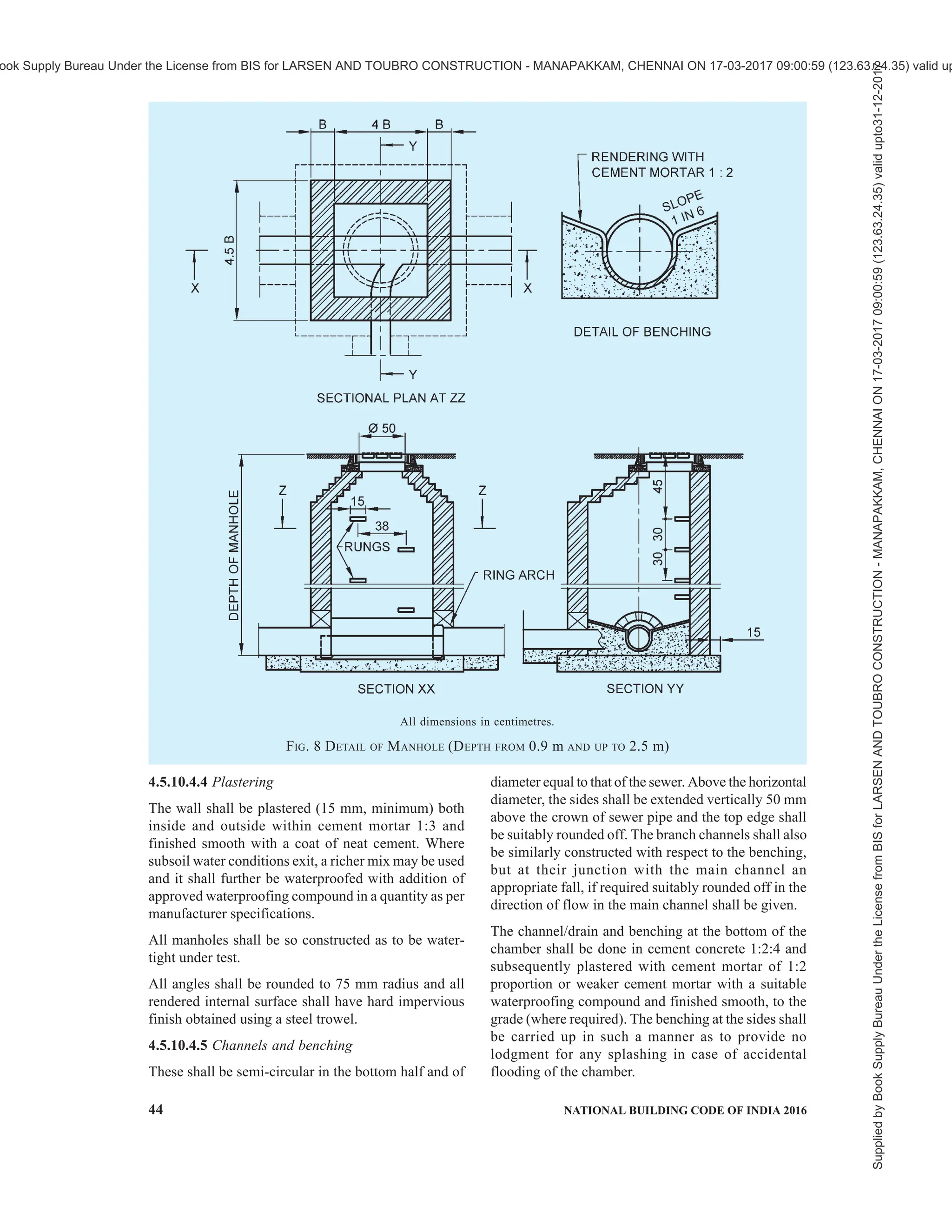
![PART 9 PLUMBING SERVICES (INCLUDING SOLID WASTE MANAGEMENT) — 45
SECTION 2 DRAINAGE AND SANITATION
Channels shall be rendered smooth and benchings shall
have slopes towards the channel.
4.5.10.4.6 Rungs
Rungs shall be provided in all manholes over 0.8 m in
depth and shall be of cast iron, or PVC encapsulated
or composite non-corrosive materials, and of suitable
dimensions, conforming to accepted standards
[9-2(14)]. These rungs may be set staggered in two
vertical rungs which may be 300 mm apart horizontally
as well as vertically and shall project a minimum of
100 mm beyond the finished surface if the manhole
wall. The top rung shall be 450 mm below the manhole
cover and the lowest not more than 300 mm above the
benching.
4.5.10.4.7 Manhole covers and frames
The size of manhole covers shall be such that there
shall be a clear opening of at least 500 mm in diameter
for manholes exceeding 0.90 m in depth. The manhole
covers and frames used shall conform to accepted
standards [9-2(15)].
The frame of manhole shall be firmly embedded to
concrete alignment and level in plain concrete on the
top of masonry.
4.5.10.5 Drop manhole
Where it is uneconomic or impracticable to arrange
the connection within 600 mm height above the invert
of the manholes, the connection shall be made by
constructing a vertical shaft outside the manhole
All dimensions in centimetres.
FIG. 9 DETAIL OF MANHOLE (DEPTH 2.5 m AND ABOVE)
Supplied
by
Book
Supply
Bureau
Under
the
License
from
BIS
for
LARSEN
AND
TOUBRO
CONSTRUCTION
-
MANAPAKKAM,
CHENNAI
ON
17-03-2017
09:00:59
(123.63.24.35)
valid
upto31-12-2017
ook Supply Bureau Under the License from BIS for LARSEN AND TOUBRO CONSTRUCTION - MANAPAKKAM, CHENNAI ON 17-03-2017 09:00:59 (123.63.24.35) valid up](https://image.slidesharecdn.com/nationalbuildingcode-240401165105-f4e9283c/75/NBC-National-Building-Code-volume-1-and-2-93-2048.jpg)
![46 NATIONAL BUILDING CODE OF INDIA 2016
chamber, as shown in Fig. 10. If the difference in level
between the incoming drain and the sewer does not
exceed 600 mm, and there is sufficient room in the
manhole, the connecting pipe may be directly brought
through the manhole wall and the fall accommodated
by constructing a ramp in the benching of the manhole.
For detailed information regarding manholes in
sewerage system, reference may be made to good
practice [9-2(16)].
All dimensions in centimetres.
NOTE — Wall thickness have been indicated in brick length to provide for use of modular bricks or traditional bricks.
In the figure, B = one brick length, 1.5 B = one an a half brick length, etc.
FIG. 10 DROP MANHOLE
Supplied
by
Book
Supply
Bureau
Under
the
License
from
BIS
for
LARSEN
AND
TOUBRO
CONSTRUCTION
-
MANAPAKKAM,
CHENNAI
ON
17-03-2017
09:00:59
(123.63.24.35)
valid
upto31-12-2017
ook Supply Bureau Under the License from BIS for LARSEN AND TOUBRO CONSTRUCTION - MANAPAKKAM, CHENNAI ON 17-03-2017 09:00:59 (123.63.24.35) valid up](https://image.slidesharecdn.com/nationalbuildingcode-240401165105-f4e9283c/75/NBC-National-Building-Code-volume-1-and-2-94-2048.jpg)
![PART 9 PLUMBING SERVICES (INCLUDING SOLID WASTE MANAGEMENT) — 47
SECTION 2 DRAINAGE AND SANITATION
4.5.10.6 Manhole covers and recommended locations
Manhole covers were traditionally and presently
manufactured from concrete, steel fibre reinforced
concrete, cast iron and ductile iron or PVC materials
and these materials are used based on the load carrying
capacity and for the following type of applications:
a) Inspection chambers for sewerage;
b) Underground electrical cabling;
c) Telecom cabling;
d) Water, gas and petroleum installations; and
e) Beautification of gardens and landscapes.
Recommended locations conforming to load capacity
shall be as per accepted standard [9-2(15)].
4.5.11 Storm Water Drainage
4.5.11.1 General
The object of storm water drainage is to collect and
carry, the rainwater collected within the premises of
the building, for suitable disposal.
4.5.11.2 Design factors
Estimate of the quantity that reaches the storm water
drain (runoff) depends on the following factors:
a) Type of soil and its absorption capacity
determined by its soil group.
b) Ground slope and the time in which the area
is drained.
c) Intensity of the rainfall for a design period.
d) Duration of the rain/storm.
The runoff reaching the sewer may be given by the
expression:
Q = 10 C.i.A
where
Q = runoff, m3
/h;
C = coefficient of runoff;
i = intensity of rainfall, mm/h; and
A = area of the drainage district, hectares.
Coefficient of runoff for various surfaces may be taken
as:
Type of Surface Coefficient of Runoff
Concrete roof area 0.9
Paved podium areas and asphalted roads 0.8
Unpaved ground 0.3
Lawns and parks 0.15
4.5.11.2.1 Imperviousness
The soil conditions and the ground slope determine the
impermeability factor. Impermeability factor is the
proportion of the total rainfall received on the surface
which will be discharging into a storm water drain after
allowing for initial abstraction (in local pond and lakes),
ground absorption by evaporation, vegetation and other
losses. The net flow reaching the storm water drain is
called runoff.
The percentage of imperviousness of the drainage area
may be obtained from available data for a particular
area. In the absence of such data, the following figures
may serve as a guide:
Type of Area Imperviousness Factor
Percent
Commercial and industrial areas 70 - 90
Residential areas (high density) 60 - 75
Residential areas (low density) 35 - 60
Parks and underdeveloped areas 10 - 20
4.5.11.2.2 Terrain modelling
Areas planned for urbanization from agricultural land,
forest or low grade land for example, low lying areas
prone to flooding, marshy or abandoned quarries, etc,
need detailed and careful consideration with respect to
its drainage. A detailed contour survey shall be carried
out not only with respect to the site but also the
surrounding areas to verify the quantity/area
contributing runoff, presence of any low lying and
natural water body acting as holding pond or any natural
drain passing through the area and beyond whose filling
up or diversion may cause water logging problem on
the site or to the surrounding areas.
The planning of the area should ensure that,
a) all areas become self draining by gravity with
respect to the high flood level of the area or
the drainage channels passing, whichever is
higher;
b) as far as possible, natural drainage pattern with
respect to the whole area be maintained except
when low lying areas need to be filled up for
grading purposes;
c) the drainage in the area shall be planned in
accordance with the natural slopes; and
d) levels of the main highway or road connecting
to the property shall be determined to ensure
proper drainage and protection of the site.
The formation levels of the entire area shall be prepared
to determine proposed formation levels by preparing a
terrain model which will show the proposed site
contours, ground and road levels and connections to
all services including storm water disposal system.
4.5.11.2.3 Rainfall intensity
The intensity of rainfall is the amount of rain falling in
Supplied
by
Book
Supply
Bureau
Under
the
License
from
BIS
for
LARSEN
AND
TOUBRO
CONSTRUCTION
-
MANAPAKKAM,
CHENNAI
ON
17-03-2017
09:00:59
(123.63.24.35)
valid
upto31-12-2017
ook Supply Bureau Under the License from BIS for LARSEN AND TOUBRO CONSTRUCTION - MANAPAKKAM, CHENNAI ON 17-03-2017 09:00:59 (123.63.24.35) valid up](https://image.slidesharecdn.com/nationalbuildingcode-240401165105-f4e9283c/75/NBC-National-Building-Code-volume-1-and-2-95-2048.jpg)

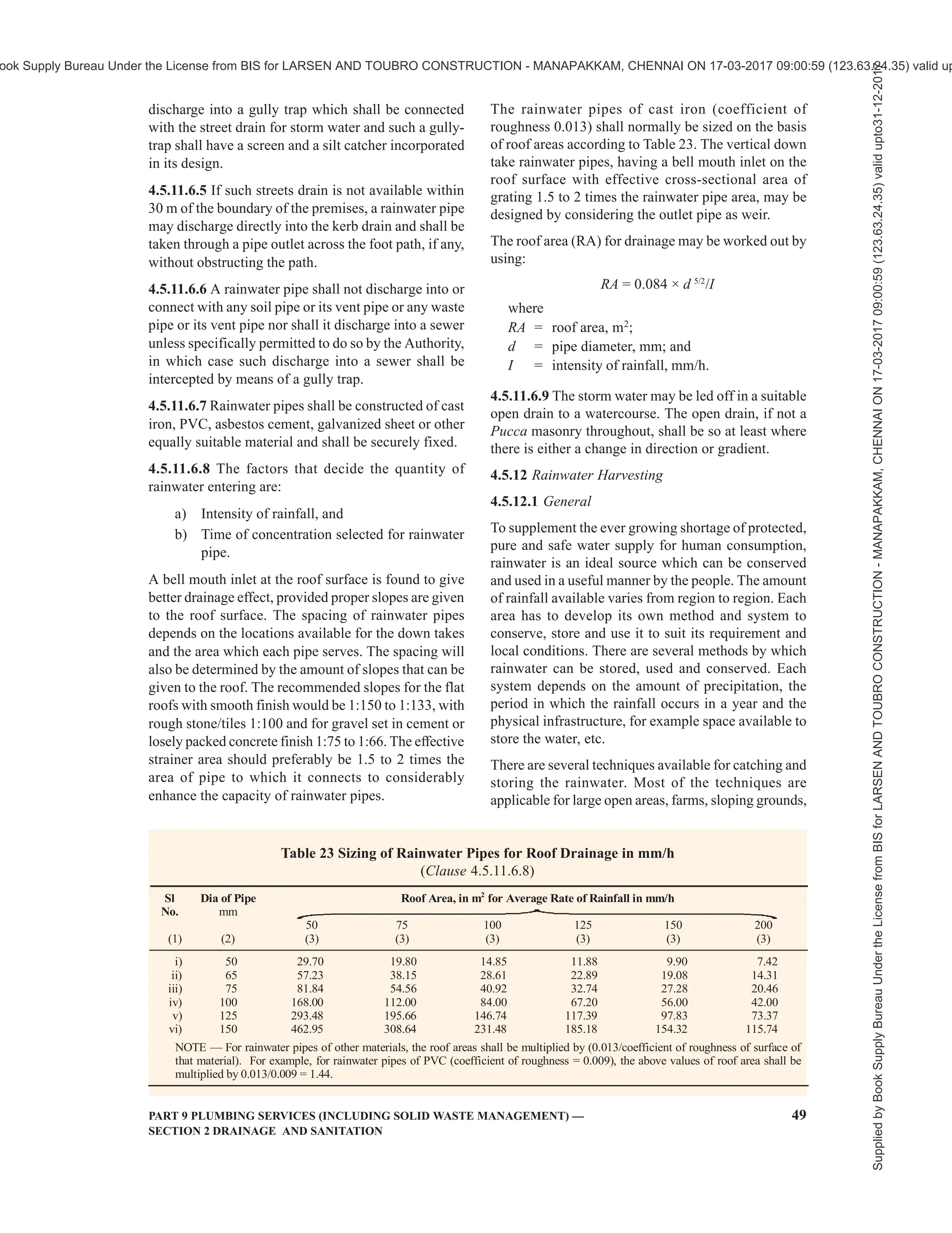
![50 NATIONAL BUILDING CODE OF INDIA 2016
etc, with a low population base. Two major systems
that are ideal for urban and semi-urban developed areas
are:
a) Artificial ground water recharge, and
b) Roof top rainwater harvesting.
NOTE — Type and number of recharge pits and roof top
rainwater harvesting capacity shall be provided as per the local/
state bye-laws.
4.5.12.2 Artificial ground water recharge
With increase in the impermeable surfaces in modern
built up areas, there is gross reduction in the original
catchment area. This prevents the natural percolation
that would have recharged the area in the normal course
if the ground was in its natural condition, for example
a farm, open ground, forest, etc. This results in a large
quantity of water, normally percolating into the ground,
running off to the natural drains and into the rivers,
causing increased runoff and flooding of downstream
areas.
It is therefore essential to catch the runoff and use it
for augmentation of ground water reservoir by
modifying the natural movement of surface water by
recharging it by artificial means, for example
construction of recharge structures (see Fig. 11). The
main objectives achieved may be:
a) Enhancement of sustainable yield in areas
where over development and depletion of the
aquifers.
b) Conservation and storage of excess surface
water in the aquifers.
c) Improve the quality of the existing ground
water through dilution.
d) Remove bacteriological and suspended
impurities during the surface water transition
within the subsoil.
e) Maintain the natural balance of the ground
water and its usage as the rainwater is a
renewable supply source. A well managed
and controlled tapping of the aquifers will
provide constant, dependable and safe water
supply.
In planning and designing the ground water recharge
structures, following should be taken into
consideration:
1) Annual rainfall (for estimating approximately
rainwater recharge per year).
2) Peak intensity and duration of each storm.
3) Type of soil and subsoil conditions and their
permeability factor.
4) Ground slopes and run off which cannot be
caught.
5) Location of recharge structures and its
overflow outfall.
6) Rainwater measuring devices for finding the
flow of water in the system.
For artificial recharge to ground water code for
guidelines for artificial recharge to ground water
[9-2(17)] may be referred.
NOTE — Rainwater harvesting with underground recharging
will depend from region to region as per the climatic,
topography, soil conditions and data about intensity of rainfall
and retention time for calculating the capacity of recharge
wells to be obtained from reference documents from the
Authority.
4.5.12.3 Roof top rainwater harvesting
4.5.12.3.1 Harvesting in regular rainfall areas
In areas having rainfall over a large period in a year,
for example in hilly areas, coastal regions, etc constant
and regular rainfall can be usefully harvested and
stored in suitable water tanks. Water shall be collected
through roof gutters and down take pipes. Provision
should be made to divert the 1st rainfall after a dry
spell so that ant dust, soot and leaves, etc, are drained
away before the water is collected into the water tank.
The capacity of the water tank should be enough for
storing water required for consumption between two
dry spells. The water tank shall be located in a well
protected area and shall not be exposed to any hazards
of water contamination from any other sources. The
water shall be chlorinated using chlorine tablets or
solution to maintain a residual chlorine of
approximately 1 mg/l. The tank shall have an overflow
leading to natural water courses or to any additional
tanks (see Table 24).
4.5.12.3.2 Harvesting in limited rainfall areas
In areas with the rainfall limited during the monsoon
period (usually from 15-90 days), roof top rainwater
can be stored and used for non-potable purposes, after
proper treatment, in the premises itself as mentioned
above; excess water, if any, is best used for recharging
the ground water. For individual properties and plots
the roof top rainwater can be diverted to underground
or above ground water storage tank(s), pretreated,
stored and used for non-potable purposes. Excess water,
if any, may be discharged to existing open or abandoned
tube wells. In a well-planned building complex, a
system should be laid out so that the runoff is collected
in underground or above ground water storage tank(s),
pretreated, stored, and used for non-potable purposes.
Excess water, if any, shall be discharged in bore-wells
as per designs specified by the Central Ground Water
Board, Government of India.
For roof top rainwater harvesting, reference may be
made to good practice [9-2(18)].
Supplied
by
Book
Supply
Bureau
Under
the
License
from
BIS
for
LARSEN
AND
TOUBRO
CONSTRUCTION
-
MANAPAKKAM,
CHENNAI
ON
17-03-2017
09:00:59
(123.63.24.35)
valid
upto31-12-2017
ook Supply Bureau Under the License from BIS for LARSEN AND TOUBRO CONSTRUCTION - MANAPAKKAM, CHENNAI ON 17-03-2017 09:00:59 (123.63.24.35) valid up](https://image.slidesharecdn.com/nationalbuildingcode-240401165105-f4e9283c/75/NBC-National-Building-Code-volume-1-and-2-98-2048.jpg)

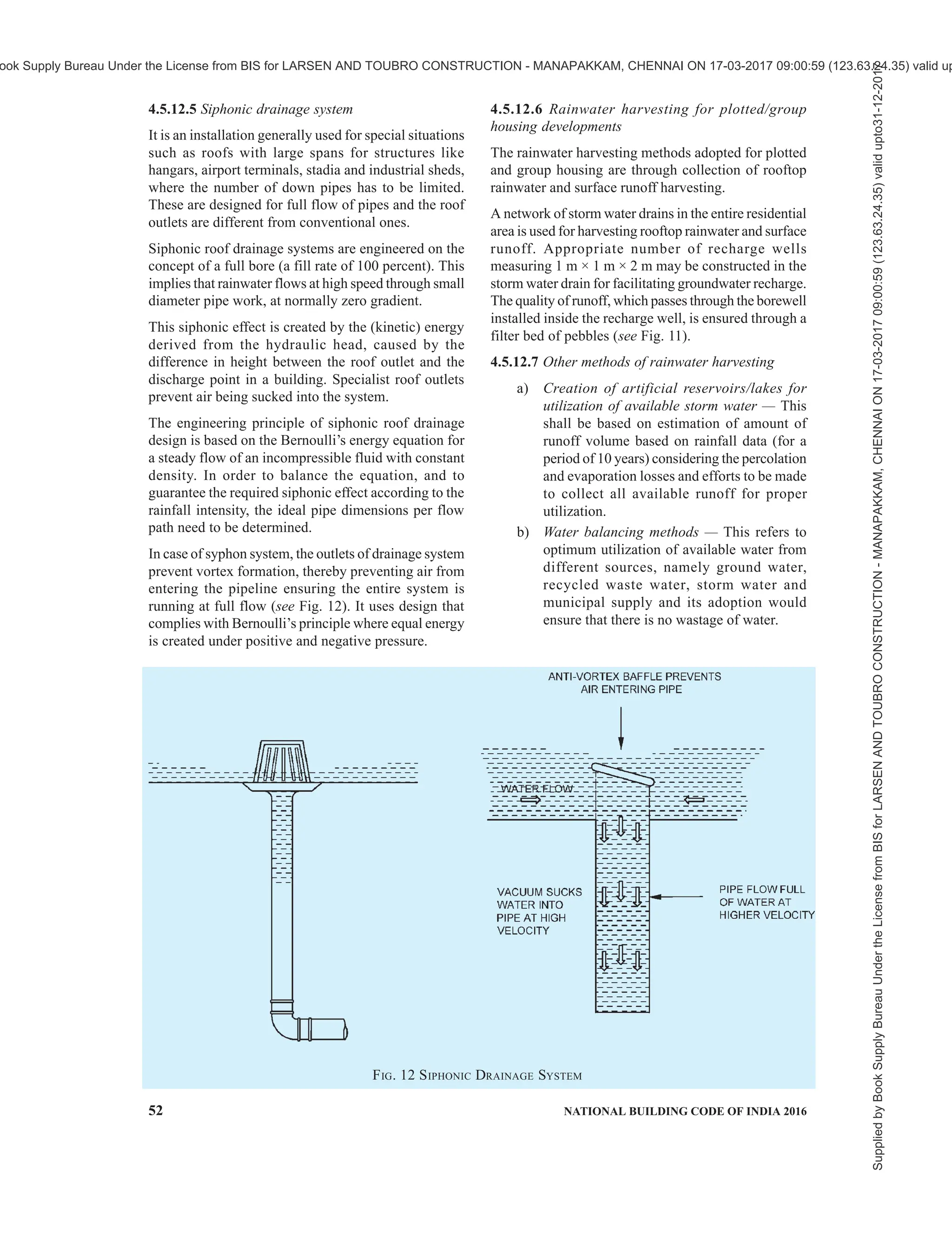
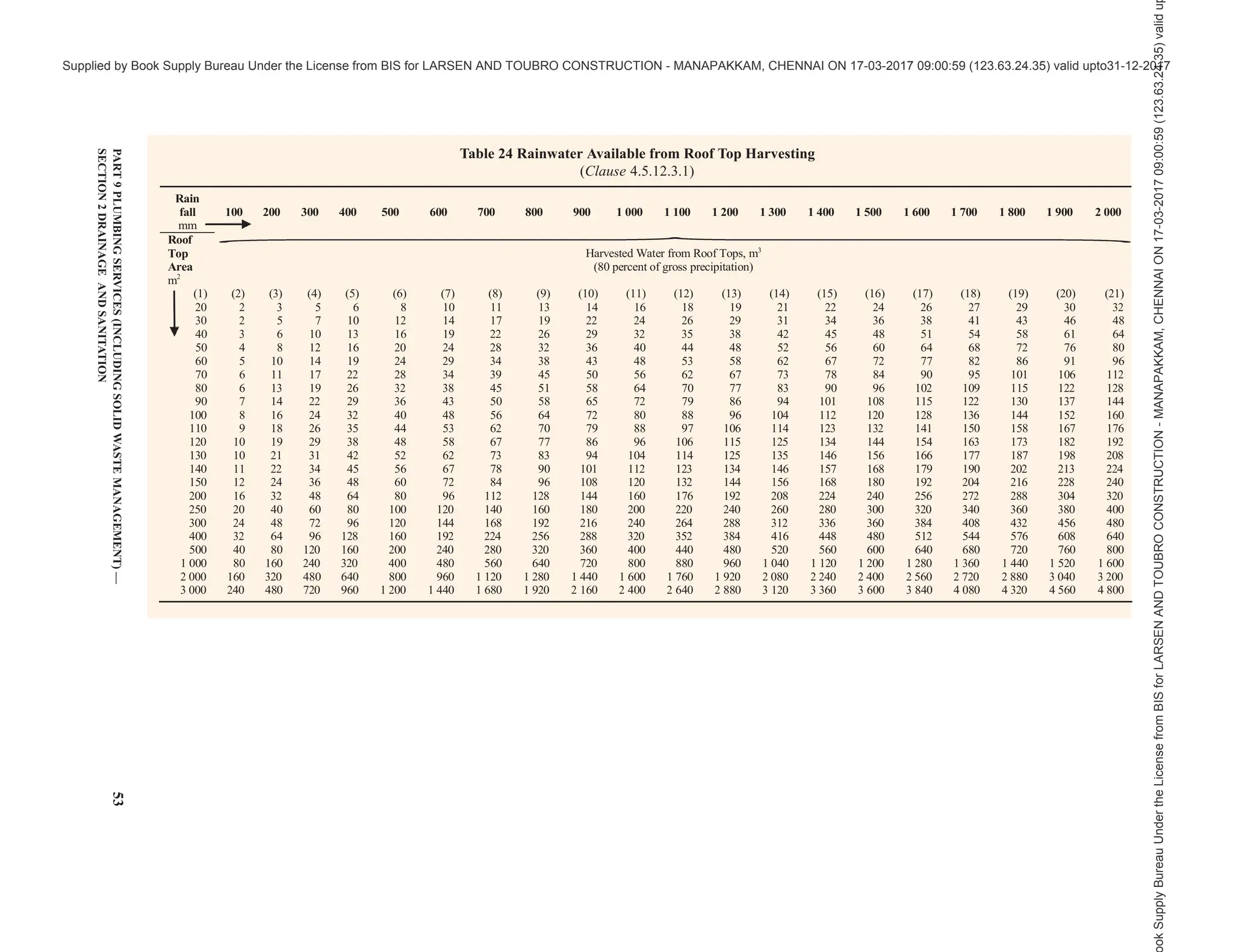

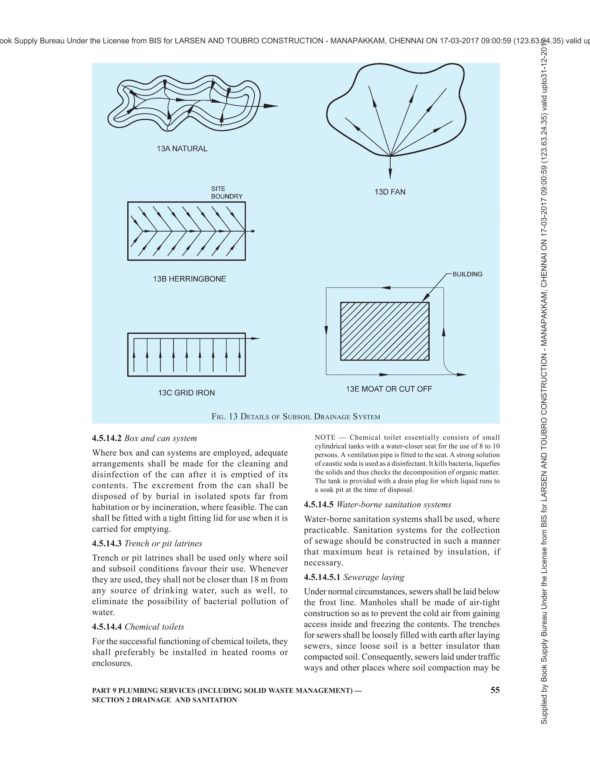
![56 NATIONAL BUILDING CODE OF INDIA 2016
expected are required to be given adequate insulation.
Where feasible, sewers shall be so located that the
trench line is not in shadow, when the sun is shining.
Concrete, cast iron and stoneware pipes conduct heat
relatively rapidly and as such should be adequately
insulated.
4.5.14.5.2 Septic tanks
Septic tanks can function only when it can be ensured
that the contents inside these do not freeze at low
temperature. For this purpose, the septic tanks shall be
located well below the frost line. The location of
manhole openings shall be marked by staves. Fencing
around the septic tanks shall be provided for
discouraging traffic over them. As the rate of biological
activity is reduced by 50 percent for every 10°C fall in
temperature, the capacity of septic tanks shall be
increased by 100 percent for operation at 10°C over that
for operation at 20°C.
The construction of septic tanks is preferred in rural
and fringe areas of suburban and isolated buildings
where underground system may neither be feasible nor
economical. Septic tanks are only recommended for
small communities and institutions whose contributory
population does not exceed 300.
For other details, see good practice [9-2(9)].
4.5.14.5.3 Seepage pits
Seepage pits can function only when the soil and subsoil
conditions are favourable. Frozen soil extending to a
great depth would preclude the use of such disposal
devices in view of the lower water absorption capacity.
The discharge of effluent should be made below the
frost line.
4.5.14.5.4 Sewage treatment plants
Suitable design modifications for sedimentation,
chemical and biological processes shall be applied to
sewage treatment plants for satisfactory functioning
(see also 4.13).
NOTE — Lavatories and bathrooms shall be kept heated to
avoid freezing of water inside traps and flushing cisterns.
4.6 Construction Relating to Conveyance of
Sanitary Wastes
4.6.1 Excavation
4.6.1.1 General
The safety precautions as given in Part 7 ‘Construction
Management, Practices and Safety’ of the Code shall
be ensured.
4.6.1.2 Turf, topsoil or other surface material shall be
set aside, turf being carefully rolled and stacked for
use in reinstatement. All suitable broken surface
material and hard-core shall be set on one side for use
in subsequent reinstatement.
4.6.1.3 Excavated material shall be stacked sufficiently
away from the edge of the trench and the size of the
spoil bank shall not be allowed to become such as to
endanger the stability of the excavation. Spoil may be
carried away and used for filling the trench behind the
work.
4.6.1.4 Excavation shall proceed to within about 75 mm
of the finished formation level. This final 75 mm is to
be trimmed and removed as a separate operation
immediately prior to the laying of the pipes or their
foundations.
4.6.1.5 Unless specified otherwise by the Authority,
the width at bottom of trenches for pipes of different
diameters laid at different depths shall be as given
below:
a) For all diameters, up to an average depth of
1 200 mm,
Width of trench, in mm = Diameter of pipe +
300 mm;
b) For all diameters for depths above 1 200 mm,
Width of trench, in mm = Diameter of pipe +
400 mm; and
c) Notwithstanding (a) and (b), the total width
of trench at the top should not be less than
750 mm for depths exceeding 900 mm.
4.6.1.6 Excavation in roads shall be so arranged, in
agreement with the proper authority, as to cause the
minimum obstruction to traffic. The methods to be
adopted shall depend on local circumstances.
4.6.1.7 All pipes, ducts, cables, mains or other services
exposed in the trench shall be effectively supported by
timber and/or chain or rope-slings.
4.6.1.8 All drainage sumps shall be sunk clear of the
work outside the trench or at the sides of manholes.
After the completion of the work, any pipes or drains
leading to such sumps or temporary subsoil drains under
permanent work shall be filled in properly with sand
and consolidated.
4.6.2 Laying of Pipes
Laying of pipes shall be done in accordance with good
practice [9-2(19)].
4.6.3 Jointing
All soil pipes, waste pipes, vent pipes and other such
pipes above ground shall be gas-tight. All sewers and
drains laid below the ground shall be water-tight.
Jointing shall be done in accordance with good practice
[9-2(19)].
Supplied
by
Book
Supply
Bureau
Under
the
License
from
BIS
for
LARSEN
AND
TOUBRO
CONSTRUCTION
-
MANAPAKKAM,
CHENNAI
ON
17-03-2017
09:00:59
(123.63.24.35)
valid
upto31-12-2017
ook Supply Bureau Under the License from BIS for LARSEN AND TOUBRO CONSTRUCTION - MANAPAKKAM, CHENNAI ON 17-03-2017 09:00:59 (123.63.24.35) valid up](https://image.slidesharecdn.com/nationalbuildingcode-240401165105-f4e9283c/75/NBC-National-Building-Code-volume-1-and-2-104-2048.jpg)

![58 NATIONAL BUILDING CODE OF INDIA 2016
4.6.5 Connection to Existing Sewers
The connection to an existing sewer shall, as far as
possible, be done at the manholes. Where it is
unavoidable to make connection in between two
manholes, the work of breaking into the existing sewer
and forming the connection shall be carried out by the
Authority or under its supervision.
4.6.5.1 Breaking into the sewer shall be effected by
the cautious enlargement of a small hole and every
precaution shall be taken to prevent any material from
entering the sewer. No connection shall be formed in
such a way as to constitute a projection into the sewer
or to cause any diminution in its effective size.
4.6.6 Back Filling
4.6.6.1 Filling of the trench shall not be commenced
until the length of pipes therein has been tested and
passed (see 4.10.2).
4.6.6.2 All timber which may be withdrawn with safety
shall be removed as filling proceeds.
4.6.6.3 Where the pipes are unprotected by concrete
haunching, the first operation in filling shall be carefully
done to hand-pack and tamp selected fine material
around the lower half of the pipes so as to buttress them
to the sides of the trench.
4.6.6.4 The filling shall then be continued to 150 mm
over the top of the pipe using selected fine hand-packed
material, watered and rammed on both sides of the pipe
with a wooden rammer. On no account shall material
be tipped into the trench until the first 150 mm of filling
has been completed. The process of filling and tamping
shall proceed evenly so as to maintain an equal pressure
on both sides of the pipeline.
4.6.6.5 Filling shall be continued in layers not
exceeding 150 mm in thickness, each layer being
watered and well rammed.
4.6.6.6 In roads, surface materials previously excavated
shallbereplacedasthetoplayerofthefilling,consolidated
and maintained satisfactorily till the permanent
reinstatement of the surface is made by the Authority.
4.6.6.7 In gardens, the top soil and turf, if any, shall be
carefully replaced.
4.7 Construction Relating to Conveyance of Rain
or Storm Water
4.7.1 Roof Gutters
Roof gutters shall be of any material of suitable
thickness. All junctions and joints shall be water-tight.
4.7.2 RainWater Pipes
Rainwater pipes shall conform to the accepted standards
[9-2(20)].
4.7.3 Subsoil Drain Pipes
4.7.3.1 Field drain pipes
Suitable pipes for this purpose are plain cylindrical
glazed water pipes, or concrete porous pipes, though
the latter may prove unsuitable where subsoil water
carries sulphates or is acidic owing to the presence of
peat. Trenches for these pipes need be just wide enough
at the bottom to permit laying the pipes, which shall be
laid with open joints to proper lines and gradients.
It is advisable to cover the pipes with clinker free from
fine ash, brick ballast or other suitable rubble, or a layer
of inverted turf, brush-wood or straw before refilling the
trench, in order to prevent the infiltration of silt through
the open joints. Where the subsoil drain is also to serve
the purpose of collecting surface water, the rubble shall
be carried up to a suitable level and when required for a
lawn or playing field, the remainder of the trench shall
be filled with pervious top soil. When refilling the
trenches, care shall be taken to prevent displacement of
pipes in line of levels. When they pass near trees or
through hedges, socket pipes with cement or bitumen
joints shall be used to prevent penetration by roots.
4.7.3.2 French drain
A shallow trench is excavated, the bottom neatly
trimmed to the gradient and the trench filled with broken
stone, gravel or clinker, coarse at the bottom and finer
towards the top.
4.8 Selection and Installation of Sanitary Appliances
Selection, installation and maintenance of sanitary
appliances shall be done in accordance with good
practice [9-2(21)].
4.9 Refuse Chute System
The refuse chute system provided shall be in accordance
with Part 9 ‘Plumbing Services, Section 3 Solid Waste
Management’ of the Code.
4.10 Inspection and Testing
4.10.1 Inspection
4.10.1.1 All sanitary appliances and fitments shall be
carefully examined for defects before they are installed
and also on the completion of the work.
4.10.1.2 Pipes are liable to get damaged in transit and,
not withstanding tests that may have been made before
despatch, each pipe shall be carefully examined on
arrival on the site. Preferably, each pipe shall be rung
with a hammer or mallet and those that do not ring true
and clear shall be rejected. Sound pipes shall be
carefully stored to prevent damage. Any defective pipes
shall be segregated, marked in a conspicuous manner
and their use in the works prevented.
Supplied
by
Book
Supply
Bureau
Under
the
License
from
BIS
for
LARSEN
AND
TOUBRO
CONSTRUCTION
-
MANAPAKKAM,
CHENNAI
ON
17-03-2017
09:00:59
(123.63.24.35)
valid
upto31-12-2017
ook Supply Bureau Under the License from BIS for LARSEN AND TOUBRO CONSTRUCTION - MANAPAKKAM, CHENNAI ON 17-03-2017 09:00:59 (123.63.24.35) valid up](https://image.slidesharecdn.com/nationalbuildingcode-240401165105-f4e9283c/75/NBC-National-Building-Code-volume-1-and-2-106-2048.jpg)

![PART 9 PLUMBING SERVICES (INCLUDING SOLID WASTE MANAGEMENT) — 61
SECTION 2 DRAINAGE AND SANITATION
be located in basement floors and leading the sewage
to onsite treatment plants. Submersible centrifugal
pumps are used for pumping the sewage. The sump
capacity depends on effective holding capacity
considering the flow from drainage fixtures. Usually,
retention period of 15 min is adopted. The size of
sump depends on the availability of space. Minimum
size of discharge pipe may be 80 mm with a velocity
of 1 m/s and pumps are sized for 100 percent design
flow.
NOTE — For other details reference to good practice [9-2(12)]
shall be made.
4.13 Sewage Treatment Systems
4.13.1 Sewage treatment is the process of removing
contaminants from waste water, primarily from
household sewage. It includes physical, chemical and
biological processes to remove these contaminants and
produce environmentally safe treated waste water
(or treated effluent).
The by-product of sewage treatment is usually a
semisolid waste or slurry, called sewage sludge, that
has to undergo further treatment before being suitable
for disposal or further application (see Fig. 17).
4.13.2 The main objective of treating waste water is to
stabilize decomposable organic matter present in the
sewage so as to produce treated effluent and sludge,
which can be disposed of in the environment without
causing health hazards or nuisance.
The microbial population in treatment process can be
cultured using the following systems:
a) Suspended growth system — In this system,
microorganisms remain in suspension and
their concentration is related to mixed liquor
suspended solids (MLSS).
b) Attached growth system — In this system,
microorganisms are developed over mobile or
immobile solid covered in biomass (slime).
c) Combined growth system — In this system,
both systems are used to attain the shock
loads.
Suspended growth system is generally proposed due
to its merits and excellent performance.
4.13.3 Technologies
Following technologies for sewage treatment shall be
considered based on the requirement:
a) Extended aeration with activated sludge
process (EAASP) — Activated sludge process
is the biological process by which non-
settleable substances occurring in dissolved
and colloidal forms are converted into
settleable sludge which is removed from the
liquid carrier (water).
This process is well suitable for completely
populated community and does not require
skilled labour for handling the plant. It is time
tested and requires more number of units to
achieve biological oxygen demand (BOD) less
than 10 ppm, like coagulants required for
better quality.
b) Sequential batch reactor (SBR) — It is an
activated sludge process designed to operate
under non-steady state conditions. An SBR
operates in a true batch mode with aeration
and sludge settlement both occurring in the
same tank. There is a degree of flexibility
associated with working in a time rather than
in a space sequence.
Plant for this process requires less space due
to batch process, well suitable for modular
growth. It can handle smallest flows and the
desired quality can be achieved without
coagulants. It requires good quality of
decanters, and skilled labour as the process is
timer-based automation.
c) Membrane bio-reactor (MBR) — It is a
continuous process of activated sludge
treatment, but solids separation is done
through pressurised system or through media.
As there is physical barrier for solid
separation, quality of treatment is good.
It is suitable for any type of growth pattern
and can handle smaller flows. It requires less
space, and skilled labours to handle.
d) Rotating bio-bed reactor (RBBR) — It is
combined growth process. Bacteria are
allowed to grow on media, which is exposed
to atmospheric air. It is also known as rotating
biological contactor (RBC).
It is suitable for smaller capacities and does
not require skilled labour to handle. The
quality of treatment is good.
e) Fluidized bio-bed reactor (FBBR) — In this
process, cells are immobilized in small
particles which move with the fluid. The small
particles create a large surface area for cells
to stick and enable a high rate of transfer of
oxygen and nutrients to the cells. It is also
known as moving bed bio reactor (MBBR). It
is suitable for all type of communities, does
not require skilled labour and requires less
space. It can be installed for all capacities and
the quality of treatment is good.
f) Submerged aerobic fixed film reactor
(SAFF) — It is a combined growth process in
Supplied
by
Book
Supply
Bureau
Under
the
License
from
BIS
for
LARSEN
AND
TOUBRO
CONSTRUCTION
-
MANAPAKKAM,
CHENNAI
ON
17-03-2017
09:00:59
(123.63.24.35)
valid
upto31-12-2017
ook Supply Bureau Under the License from BIS for LARSEN AND TOUBRO CONSTRUCTION - MANAPAKKAM, CHENNAI ON 17-03-2017 09:00:59 (123.63.24.35) valid up](https://image.slidesharecdn.com/nationalbuildingcode-240401165105-f4e9283c/75/NBC-National-Building-Code-volume-1-and-2-109-2048.jpg)


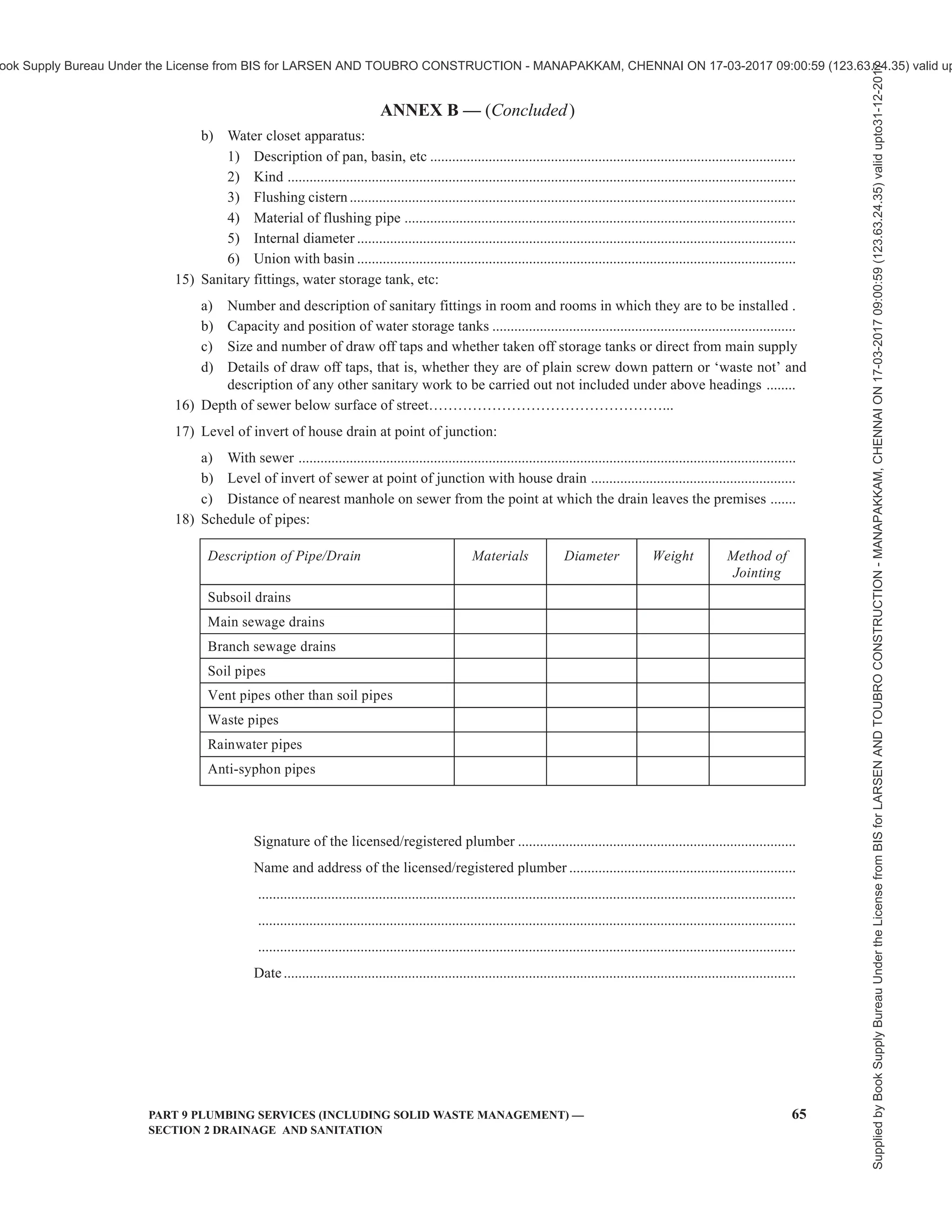


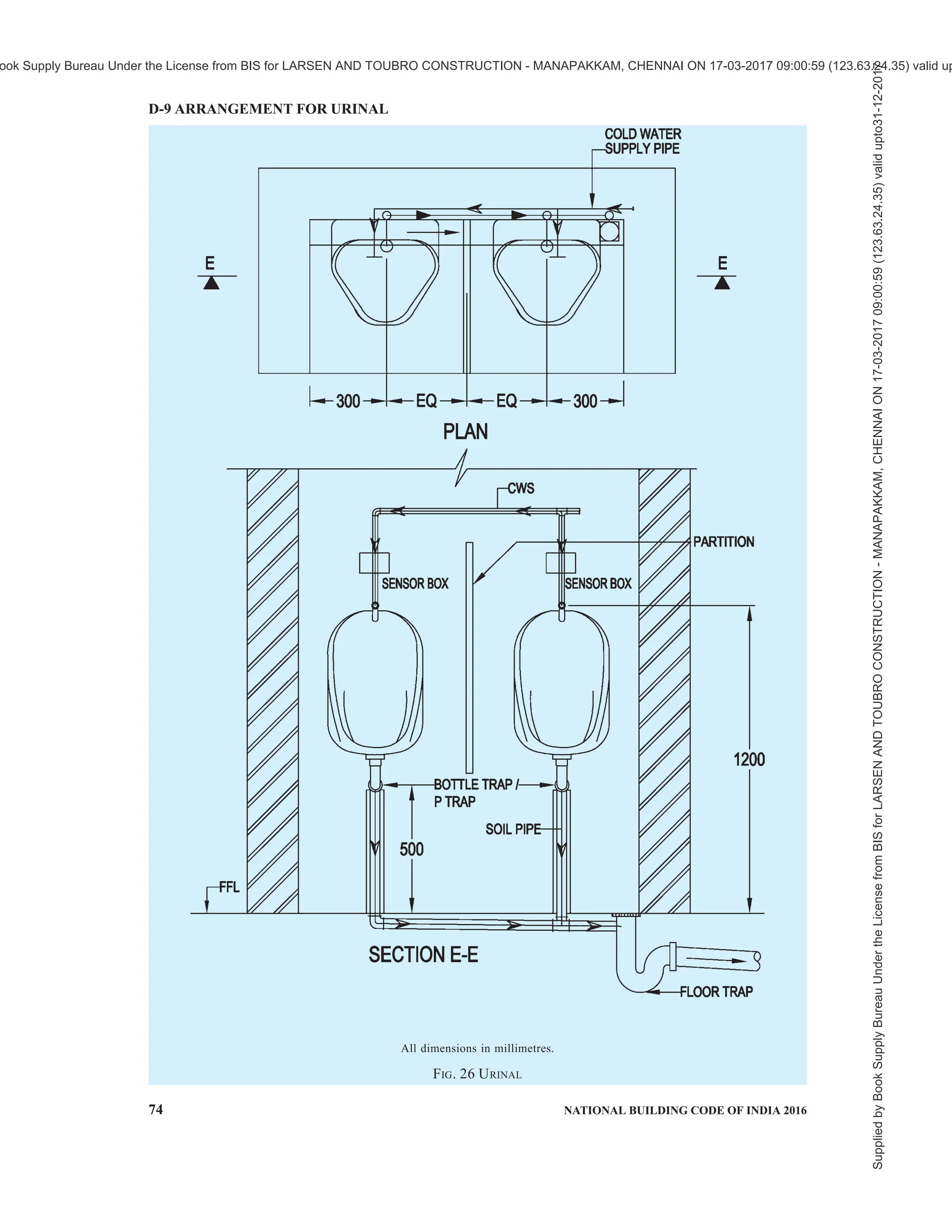


![PART 9 PLUMBING SERVICES (INCLUDING SOLID WASTE MANAGEMENT) — 5
SECTION 3 SOLID WASTE MANAGEMENT
emissions, slope instability and erosion.
2.11 Leachate — Liquid that seeps through solid
wastes or other medium and has extracts of dissolved
or suspended material from it.
2.12 Municipal Authority — Municipal Corporation,
Municipality, Nagar Palika, Nagar Nigam, Nagar
Panchayat, Municipal Council including notified area
committee (NAC) or any other local body constituted
under the relevant statutes and, where the management
and handling of municipal solid waste is entrusted to
such agency.
2.13 Municipal Solid Waste — Commercial and
residential wastes generated in municipal or notified
areas in either solid or semi-solid form, excluding
industrial hazardous wastes and construction and
demolition waste but including treated bio-medical
wastes.
2.14 Operator of a Facility — A person who owns or
operates a facility for collection, segregation, storage,
transportation, processing and disposal of municipal
solid wastes and also includes any other agency
appointed as such by the municipal authority for the
management and handling of municipal solid wastes
in the respective areas.
2.15 Pelletization — A process whereby pellet are
prepared which are small cubes or cylindrical pieces
made out of solid wastes and includes fuel pellets which
are also referred as refuse derived fuel.
2.16 Processing — The process by which solid wastes
are transformed into new or recycled products.
2.17 Recycling — The process of transforming
segregated solid wastes into raw materials for producing
new products, which may or may not be similar to the
original products.
2.18 Segregation — To separate the municipal solid
wastes into the groups of organic, inorganic, recyclables
and hazardous wastes.
2.19 Storage — The temporary containment of
municipal solid wastes in a manner so as to prevent
littering, attraction to vectors, stray animals and
excessive foul odour.
2.20 Transportation — Conveyance of municipal solid
wastes from place to place hygienically through
1 SCOPE
This Code (Part 9/Section 3) covers the solid waste
management systems, assessment of per capita solid
waste quantities and treatment of solid waste within
the building, building complexes and their built
environments.
2 TERMINOLOGY
For the purpose of this Section, the following definitions
shall apply, and for other terms those given in the
accepted standard [9-3(1)] shall apply.
2.1 Anaerobic Digestion — A controlled process
involving microbial decomposition of organic matter
in the absence of oxygen.
2.2 Authorization — The consent given by the State
Pollution Control Board or Pollution Control
Committee, as the case may be, to the operator of a
facility.
2.3 Biodegradable Substance — A substance that can
be degraded by microorganisms into simpler stable
compounds.
2.4 Biomethanation — A process which entails
enzymatic decomposition of the organic matter by
microbial action to produce methane rich biogas.
2.5 Collection — Lifting and removal of solid wastes
from collection points or any other location.
2.6 Composting — A controlled process involving
microbial decomposition of organic matter.
2.7 Construction and Demolition Waste — Wastes
from building materials debris and rubble resulting from
construction, re-modelling, repair and demolition
operation.
2.8 Disposal — Final disposal of municipal solid wastes
in accordance with the specified measures to prevent
contamination of groundwater, surface water and
ambient air quality.
2.9 Generator of Wastes — Persons or establishments
generating municipal solid wastes.
2.10 Landfilling — Disposal of residual solid wastes
on land in a facility designed with protective measures
against pollution of groundwater, surface water and air
fugitive dust, wind-blown litter, bad odour, fire hazard,
bird menace, pests or rodents, greenhouse gas
NATIONAL BUILDING CODE OF INDIA
PART 9 PLUMBING SERVICES
(INCLUDING SOLID WASTE MANAGEMENT)
Section 3 Solid Waste Management
Supplied
by
Book
Supply
Bureau
Under
the
License
from
BIS
for
LARSEN
AND
TOUBRO
CONSTRUCTION
-
MANAPAKKAM,
CHENNAI
ON
17-03-2017
09:00:59
(123.63.24.35)
valid
upto31-12-2017
ook Supply Bureau Under the License from BIS for LARSEN AND TOUBRO CONSTRUCTION - MANAPAKKAM, CHENNAI ON 17-03-2017 09:00:59 (123.63.24.35) valid up](https://image.slidesharecdn.com/nationalbuildingcode-240401165105-f4e9283c/75/NBC-National-Building-Code-volume-1-and-2-135-2048.jpg)


![PART 9 PLUMBING SERVICES (INCLUDING SOLID WASTE MANAGEMENT) — 9
SECTION 3 SOLID WASTE MANAGEMENT
a) Sanitation system for internal cleaning of
chutes, with sprinklers at every floor intake
level, with disinfectant cleaning, which may
preferably be automatic in operation;
b) Exhaust system with 25 to 35 air changes per
hour;
c) Discharge end fire resistant door;
d) Chute may be of masonry, R.C.C. pipe,
asbestos cement pipe or suitable non-corrosive
material, preferably stainless steel. It should
be rigid with smooth internal finish, high
ductility and alkali/acid resistant properties
{see also good practice [9-3(2)]};
e) Fire rating shall comply with 3.4.8.3 of Part 4
‘Fire and Life Safety’ of the Code;
f) Fire sprinklers shall be provided inside chute;
g) Vent shall be installed at roof level to remove
foul smell and gases generated;
h) Chute should discharge to trolley directly;
j) Necessary automation of the system may be
planned to avoid malfunction by manual
operation; and
k) All care shall be taken for ensuring
accessibility to the chute for persons with
disabilities. The opening of the chute shall not
be higher than 700 mm and there shall be a
clear space of minimum 1 500 mm ×
1 500 mm in front of the chute opening to gain
easy access even for persons using
wheelchairs. There may be high colour
contrast provided around the chute opening
to make it easy to identify it. The flooring in
front of the chute opening may be texturally
highly different from the rest of the floor.
4.3.3 Refuse Collection Chamber
The collection chamber may be located in ground floor
or basement level, provided appropriate arrangement
is made for drainage of the collection pit by gravity
flow to ensure its dryness, an appropriate ramp access
is provided for convenient removal of garbage from
the collection pit, and satisfactory ventilation is
provided for escape of gas and odour.
The floor of the chamber shall be provided with
drainage through a 100 mm diameter trap and screen
to prevent any solid matters flowing into the drain and
the drain shall be connected to the sewer line. The floor
shall be finished with smooth hard surface for
convenient cleaning.
The height of the collection chamber and vertical
clearance under the bottom level of garbage chute shall
be such that the garbage trolley can be conveniently
placed.
The collection chamber shall be provided with
appropriate shutter to prevent access of scavenging
animals like cattle, dogs, cats and rats.
4.3.4 Refuse Collection Room
The refuse collection room should be planned in ground
or basement level with appropriate ventilation and
proper drainage. The room should have access for
vehicle or trolley transfer of garbage.
4.3.5 See also accepted standards [9-3(3)].
4.4 Dumb-Waiter or Service Lift
In high rise buildings with more than 5 storeys,
electrically operated dumb-waiters may be used for
carrying domestic garbage in packets or closed
containers. For handling of garbage by dumb-waiters
in a building, a garbage chamber shall have to be
provided either at ground floor or basement level and
the provisions of garbage collection chamber for chute
as given in 4.3 shall apply.
5 ASSESSMENT OF PER CAPITA WASTE
QUANTITY
5.1 For purposes of this Section, the following
municipal refuse generation rates are recommended:
a) Residential refuse : 0.3 to 0.6 kg/capita/day
b) Commercial refuse : 0.1 to 0.2 kg/capita/day
c) Street sweepings : 0.05 to 0.2 kg/capita/
day
d) Institutional refuse : 0.05 to 0.2 kg/capita/
day
Out of the total solid waste generated, 40 percent may
be taken as organic waste and 60 percent as inorganic
waste. The knowledge of chemical characteristics of
waste is important for selecting and designing the waste
processing and disposal facilities.
5.2 These generation rates are subject to considerable
site-specific factors and are required to be supported
by field data. The waste contains a high percentage of
ash and fine earth. The calorific value of Indian solid
waste varies between 800 and 1 000 kcal/kg and the
density varies between 300 and 500 kg/m3
.
5.3 Other than municipal solid waste, the following
types of waste may also be generated in urban centers:
a) Industrial waste — Hazardous and non-
hazardous waste from industrial areas within
municipal limits.
b) Bio-medical waste — Waste from hospitals,
slaughter houses, etc.
c) Thermal power plant waste — Fly ash from
coal-based electricity generating plant within
municipal limits.
Supplied
by
Book
Supply
Bureau
Under
the
License
from
BIS
for
LARSEN
AND
TOUBRO
CONSTRUCTION
-
MANAPAKKAM,
CHENNAI
ON
17-03-2017
09:00:59
(123.63.24.35)
valid
upto31-12-2017
ook Supply Bureau Under the License from BIS for LARSEN AND TOUBRO CONSTRUCTION - MANAPAKKAM, CHENNAI ON 17-03-2017 09:00:59 (123.63.24.35) valid up](https://image.slidesharecdn.com/nationalbuildingcode-240401165105-f4e9283c/75/NBC-National-Building-Code-volume-1-and-2-139-2048.jpg)

![PART 9 PLUMBING SERVICES (INCLUDING SOLID WASTE MANAGEMENT) — 11
SECTION 3 SOLID WASTE MANAGEMENT
Sorted garbage free from inert and toxic matters shall
be applied in the composting pit in layers of 75 mm
and spread, and covered with a layer of 75 mm thick
dry leaves, followed by sprinkling of water.
The compost may be removed from the bottom of the
compost pit after intervals of 3 to 6 months. The
compost so made may be used in appropriate
horticultural and related applications.
See also accepted standard [9-3(4)] for manure grade
municipal solid waste compost.
6.3 Thermal Processes
Thermal treatment involves conversion of waste into
gaseous, liquid and solid conversion products with
concurrent or subsequent release of heat energy.
Three types of systems can be adopted, namely:
a) Combustion systems (Incinerators) — Thermal
processing with excess amounts of air.
b ) Pyrolysis systems — Thermal processing in
complete absence of oxygen (low
temperature).
c) Gasification systems — Thermal processing
with less amount of air (high temperature).
6.4 Land Filling
6.4.1 Disposal of waste on lands identified for the
purpose is typical of this method of waste disposal.
The depth of filling depends upon the site topography
and location and varies from deep to shallow filling. A
municipal solid waste landfill plant is an engineered
facility used for disposal of solid waste. Landfills in
which municipal waste is placed are designated as
‘MSW landfills’. The main considerations in respect
of landfill sites are:
a) Specifications for landfill sites,
b) Site selection,
c) Facilities at site, and
d) Specification of land filling.
6.4.2 Improper landfill generally impacts the
environment in the following ways:
a) Groundwater contamination by the leachate
generated by the waste dump;
b) Surface water contamination by the run-off
from the waste dump;
c) Bad odour, pests, rodents and wind-blown
litter in and around the waste dump;
d) Generation of inflammable gas (for example,
methane) within the waste dump;
e) Bird menace above the waste dump which
affects flight of aircraft;
f) Fires within the waste dump;
g) Erosion and stability problems relating to
slopes of the waste dump;
h) Epidemics through stray animals;
j) Acidity to surrounding soil; and
k) Release of greenhouse gas.
6.5 Some recycling/treatment methods for food waste
are given in Annex B for guidance.
6.6 See also accepted standards [9-3(5)] for solid waste
management, and for analysis and testing of solid
wastes.
6.7 Other/special wastes shall be dealt with in
accordance with the statutory provisions in respect of
the same (see 3.4).
Supplied
by
Book
Supply
Bureau
Under
the
License
from
BIS
for
LARSEN
AND
TOUBRO
CONSTRUCTION
-
MANAPAKKAM,
CHENNAI
ON
17-03-2017
09:00:59
(123.63.24.35)
valid
upto31-12-2017
ook Supply Bureau Under the License from BIS for LARSEN AND TOUBRO CONSTRUCTION - MANAPAKKAM, CHENNAI ON 17-03-2017 09:00:59 (123.63.24.35) valid up](https://image.slidesharecdn.com/nationalbuildingcode-240401165105-f4e9283c/75/NBC-National-Building-Code-volume-1-and-2-141-2048.jpg)


![PART 9 PLUMBING SERVICES (INCLUDING SOLID WASTE MANAGEMENT) — SECTION 4 GAS SUPPLY 7
d) If any condition exists which threatens
interruption of gas supply which may cause
burner outage or otherwise prove dangerous.
7.2 It shall be the duty of the installing agency when
the gas supply is to be turned off to notify all affected
consumers.
7.3 Before turning off the gas at the meter, for the
purpose of installation, repair, replacement or
maintenance of piping or appliance, all burner and pilot
valves on the premises supplied with gas through the
meter shall be turned off and the meter test hand
observed for a sufficient length of time to ascertain that
there is no gas passing through the meter. Where there
is more than one meter on the premises, precaution shall
be exercised to ensure that the concerned meter is turned
off.
8 INSTALLATION OF GAS PIPES
8.1 Installation, repair and replacement of gas piping
or appliances shall be performed only by a qualified
installing agency.
8.2 Piping
8.2.1 Piping shall be of wrought iron, steel, copper,
stainless steel or cast iron when the gas pressure is less
than 7 kN/m2
; with higher gas pressure use of cast iron
shall be prohibited.
8.2.1.1 SS 316/304/321 and flexible PE coated flexible
pipe in rolls shall be permitted in low pressure system
provided the pipe meets the required standard, to avoid
the bends, fittings and leakages from the joint which
are potential leakage points. Also, reference may be
made to accepted standard [9-4(1)]. Heavy rubber
flexible tube shall be permitted only as direct
connection to burner from appliance valve.
8.2.1.2 For details regarding medical gas pipeline
systems, a reference may be made to good practice
[9-4(2)].
8.2.2 Size of Gas Piping
Gas piping shall be of such size and so installed as to
provide supply of gas sufficient to meet the maximum
demand without undue loss of pressure between the
meter or service regulator when a meter is not provided,
and the appliance(s).
8.2.2.1 The size of gas piping depends upon the
following factors:
a) Allowable loss in pressure from meter or
service regulator, when a meter is not
provided, to appliance;
b) Maximum consumption to be provided;
c) Length of piping and number of fittings; and
d) Specific gravity of gas.
8.2.2.2 No gas pipe smaller than 8 mm shall be used.
8.2.3 As far as possible, straight lengths of piping should
be used. Where there are bends in the pipe line, these
should have a radius of at least five times the diameter
of the pipe.
8.2.4 For any thread joint proper sealant shall be used
on male threads only.
8.3 The gas piping shall be of the colour stipulated by
explosive authority to distinguish it from other piping
and the piping shall be painted silver grey with red band
of 150 mm width. The gas pipeline shall be painted
canary yellow in case of natural gas.
8.4 Piping Underground
8.4.1 Protection of Piping
Piping shall be buried to a minimum depth of 1 m or
covered in a manner so as to protect the piping from
physical damage.
8.4.2 Protection Against Corrosion
Generally all the piping within the premises where it
has to run on the wall shall be exposed and should not
be in contact with wall to ensure that no corrosion takes
place. Epoxy sealant or polyethylene conduit shall be
used to ensure no contact of pipe with the wall in the
situation of pipe crossing the wall. Underground or
concealed gas pipeline in contact with earth or other
materials which may corrode the piping shall be
protected against corrosion by application of adequate
corrosion resistant coating backed up by cathodic
protection system.
8.5 The building shall not be weakened by the
installation of any gas piping.
8.6 Gas piping in building shall be supported with pipe
hooks, metal pipe straps, bonds or hangers suitable for
the size of piping and of adequate strength and quality
and located at proper intervals so that the piping may
not be moved accidentally from the installed position.
8.7 Pipe Entrance to Buildings
Where gas pipe enters a building through a wall or floor
of masonry or concrete, any gas piping or other piping
entering the walls or floors shall be suitably sealed
against the entrance of water/moisture or gas.
The openings or imperfection of fit or design are also
source of possible fire and smoke passing through them.
Fire stops shall be provided to fill the openings around
penetrating items such as gas pipes, etc, through the
wall or floor openings. Non-combustible sleeving may
Supplied
by
Book
Supply
Bureau
Under
the
License
from
BIS
for
LARSEN
AND
TOUBRO
CONSTRUCTION
-
MANAPAKKAM,
CHENNAI
ON
17-03-2017
09:00:59
(123.63.24.35)
valid
upto31-12-2017
ook Supply Bureau Under the License from BIS for LARSEN AND TOUBRO CONSTRUCTION - MANAPAKKAM, CHENNAI ON 17-03-2017 09:00:59 (123.63.24.35) valid up](https://image.slidesharecdn.com/nationalbuildingcode-240401165105-f4e9283c/75/NBC-National-Building-Code-volume-1-and-2-153-2048.jpg)

![PART 9 PLUMBING SERVICES (INCLUDING SOLID WASTE MANAGEMENT) — SECTION 4 GAS SUPPLY 9
10 LEAKAGE CHECK
10.1 Before turning gas under pressure into any piping,
all openings from which gas may escape shall be closed.
10.2 Checking for Gas Leakage
No matches, flame or other sources of ignition shall be
employed to check for gas leakage from meters, piping
or appliances. Checking for gas leakage with soap and
water solution is recommended.
10.3 Use of Lights
Artificial illumination used in connection with a search
of gas leakage shall be restricted to electric hand flash
lights (preferably of the safety type) or approved safety
lamps. In searching for leaks, electric switches should
not be operated. If electric lights are already turned
on, they should not be turned off.
10.4 Checking for Leakage with Meter
Immediately after turning gas into the piping, the system
shall be checked to ascertain that no gas is escaping.
This may be done by carefully watching the test dial of
the meter to determine whether gas is passing through
the meter. In no case should a leakage test be made
using a gas meter unless immediately prior to the test it
has been determined that the meter is in operating
condition.
10.5 Checking of Leakage Without Using a Meter
This may be done by attaching to an appliance, orifice
or a manometer or equivalent device and momentarily
turning on the gas supply and deserving the gauging
device for pressure drop with the gas supply shut-off.
No discernible drop in pressure shall occur during a
period of 3 min.
10.6 After piping has been checked, all gas piping shall
be fully purged. Piping shall not be purged into the
combustion chamber of an appliance. A suggested
method for purging the gas piping to an appliance is to
disconnect the pilot piping at the outlet of the pilot
valve.
10.7 After the gas piping has been effectively purged,
all appliances shall be purged and the pilots lighted.
10.8 In addition to the checking of gas leakage with
soap and water solution, a suitable gas detector is also
recommended for use.
11 USE OF LIQUEFIED PETROLEUM GAS
(LPG)
11.1 The cylinders used for the storage and
transportation of liquefied petroleum gas (LPG) shall
conform to accepted standards [9-4(3)] approved by
the statutory authority.
11.2 The handing, use, storage and transportation of
liquefied petroleum gas in cylinders exceeding 500 ml
water capacity shall be done in accordance with good
practice [9-4(4)].
11.3 LPG Cylinder Installation
The following recommendations apply to installation
in commercial, industrial, educational and institutional
premises.
11.3.1 General Recommendations
11.3.1.1 Those responsible for the installation of
cylinders, equipment and piping should understand the
characteristics of LPG and be trained in good practice
of handling, installing and maintaining installations.
11.3.1.2 The jointing compound used at different joints
in the system shall be decided by the Qualified Installing
Agency. Hemp and similar materials shall not be used
at the joint. In any joint in which the thread provides a
gastight seal, jointing compound shall be used only on
the male thread.
11.3.1.3 Fire extinguishers of dry powder type or carbon
dioxide type conforming to accepted standards [9-4(5)]
shall be provided in places where LPG cylinder
installations are situated and shall be located near such
installations. Two buckets filled with sand and two with
water shall also be installed nearby. The number, type
and size of the fire extinguishers shall be as follows:
Number Type Capacity
a) For installations
with LPG 40 kg
to 200 kg
2 Dry
powder
9 kg
b) For installations
with LPG more
than 200 kg and
up to 320 kg
3 Dry
powder
9 kg
c) For installations
with LPG more
than 320 kg and
up to 1 000 kg
4 Dry
powder
9 kg
NOTE — For electrical installations, one number CO 2 fire
extinguisher (4.5 kg capacity) shall be provided.
11.3.1.4 Liquefied petroleum gas shall not be
transferred from the cylinders in which it is received to
any other container.
11.3.2 Cylinder Location
11.3.2.1 Stationary installations
a) Stationary installation not exceeding 50 kg of
LPG may be installed indoors on any floor. It
is recommended to have a minimum floor area
of 5 m2
for such an installation.
Supplied
by
Book
Supply
Bureau
Under
the
License
from
BIS
for
LARSEN
AND
TOUBRO
CONSTRUCTION
-
MANAPAKKAM,
CHENNAI
ON
17-03-2017
09:00:59
(123.63.24.35)
valid
upto31-12-2017
ook Supply Bureau Under the License from BIS for LARSEN AND TOUBRO CONSTRUCTION - MANAPAKKAM, CHENNAI ON 17-03-2017 09:00:59 (123.63.24.35) valid up](https://image.slidesharecdn.com/nationalbuildingcode-240401165105-f4e9283c/75/NBC-National-Building-Code-volume-1-and-2-155-2048.jpg)
![10 NATIONAL BUILDING CODE OF INDIA 2016
b) Stationary installations each not exceeding
50 kg of LPG may be installed indoors on any
floor and within the same workspace provided
the minimum distance between two such
installations is 3 m, the proportion of such
installations to floor area is one installation
per 5 m2
and the aggregate quantity of gas of
all such installations does not exceed 200 kg.
c) Stationary installation not exceeding 100 kg
of LPG may be installed indoors on any floor
provided the floor area for such an installation
is not less than 12 m2
.
d) Stationary installations each not exceeding
100 kg of LPG may be installed indoors on
any floor and within the same workspace
provided the minimum distance between two
such installations is 3 m, the proportion of such
installations to floor area is one installation
per 12 m2
and the aggregate quantity of gas of
all such installations does not exceed 200 kg.
e) Stationary installation not exceeding 400 kg
of LPG may be installed indoors in an
enclosed section of a building or a room
reserved exclusively for this purpose and
ventilated at low level directly to the outside
air.
f) Stationary installations above 400 kg [200 kg
in case provision as in (e) is not possible] but
not exceeding 1 000 kg shall be installed
outdoors on ground floor level only. A
minimum distance of 3 m shall be maintained
between an installation and any building,
public place, roadways, and other
surroundings. The installation shall be
protected from excessive weathering by sun,
rain, etc, and from tampering by unauthorized
persons. A lean-to roof with expanded metal
on angle-iron framework on the sides is
considered suitable for this purpose. In any
case, adequate ventilation at ground level to
the outside air shall be provided.
g) If the storage per installation is more than
1 000 kg, installations in multiples of 1 000 kg
with manifold, safety devices, change over
mechanism may be provided with minimum
inter distance of 3 m from all sides. Total
number of such installations shall not exceed
4 including stand by installation. If more than
two installations are used, then number of
cylinders per installations should not
exceed 30.
h) For storage installations of 1 000 kg or
installations in multiple of 1 000 kg the
number of cylinders to be connected per
manifold shall not exceed 15 and for each
1 000 kg installation two such manifolds shall
be provided.
j) Cylinders shall be installed upright with the
valves uppermost.
k) Cylinder containing more than 20 kg of gas
shall not be located on floors above ground
level.
m) Cylinders shall be located on a concrete or
brick floor, preferably raised in case of
outdoor installations.
n) In order to prevent the hazardous collection
of gas, cylinders shall be placed at least 1 m
away from culverts, depressions, or openings
leading to below ground level compartment
and drains.
p) Cylinders which have safety relief valves or
similar devices incorporated in them shall be
so positioned so that if the relief device
operates, escaping gas is not hazardous.
q) Cylinder installation for commercial/
industrial/domestic/residential complexes, etc,
or at any public place shall meet the following
requirements:
1) For commercial and industrial cylinder
installation for any public places like
mall, buildings, industries, hotels, etc, the
sum total of all stationery installations
inside the building shall not exceed
400 kg of LPG in any case. In case sum
total of net weight of all the cylinders
installed indoors exceed 400 kg provision
for outdoor installations shall be made.
For installations where the sum total is
less than 400 kg of LPG provisions of (b)
to (e) shall apply.
2) For commercial and industrial cylinder
installation for any public place, industry,
etc, if the net weight of all the cylinders
installed is more than 400 kg but less than
1 000 kg, than the installation shall be
provided outdoors in line with (f). The
cylinder installation shall be provided in
a covered industrial shed but open from
all sides for proper ventilation. In case
the installed capacity increases more than
1 000 kg, than the installation shall be
provided in line with (g). Two separate
installations shall be provided and
distance between each of the installations
shall be minimum 3 m (this distance shall
be between the outer edge of the two
sheds).
3) For multi-storeyed buildings, flats
housing society the reticulated installation
of any capacity shall be provided at a safe
Supplied
by
Book
Supply
Bureau
Under
the
License
from
BIS
for
LARSEN
AND
TOUBRO
CONSTRUCTION
-
MANAPAKKAM,
CHENNAI
ON
17-03-2017
09:00:59
(123.63.24.35)
valid
upto31-12-2017
ook Supply Bureau Under the License from BIS for LARSEN AND TOUBRO CONSTRUCTION - MANAPAKKAM, CHENNAI ON 17-03-2017 09:00:59 (123.63.24.35) valid up](https://image.slidesharecdn.com/nationalbuildingcode-240401165105-f4e9283c/75/NBC-National-Building-Code-volume-1-and-2-156-2048.jpg)
![12 NATIONAL BUILDING CODE OF INDIA 2016
a) The sum total of capacity of the cylinders
connected to each manifold shall not exceed
100 kg of LPG. The total quantity of gas thus
installed in a workspace shall not exceed
200 kg.
b) If cylinders are mounted on a trolley, the
trolley shall be stable. Where necessary, the
cylinders shall be secured to prevent them
from falling.
c) The regulator shall be connected directly to
the cylinder valve or to a manifold which shall
be connected to the cylinder valves by means
of rigid connections to give adequate support
to the regulator. The only exception to this
requirement is where cylinders are mounted
on a trolley and the manifold is rigidly
supported on the trolley. In such a case flexible
or semi-flexible connections may be used
between the cylinder valves and the manifold
but not between the manifold and the
regulator.
d) Anytime the total quantity of gas at portable
installations shall be in proportion to the floor
area as specified in 11.3.2.1 (a) to (f).
e) At any time the provisions at 11.3.2.1 (a) to
(r) shall be ensured for all installations.
11.3.3 Cylinder Manifolds
11.3.3.1 All materials, fittings, etc, used in cylinder
manifold systems shall comply with the statutory
provisions or relevant Indian Standards. In absence of
any such provisions or Indian Standards, equivalent
international norms shall be followed.
11.3.3.2 The individual component parts of manifolds,
that is piping, fittings, pigtails, etc, which are subject
to cylinder pressure shall be capable of withstanding a
test pressure without bursting of 2.5 N/mm2
or one and
a half times the developed pressure at 65o
C, whichever
is more.
11.3.3.3 Where cylinder installations are made up with
service and reserve batteries of cylinders, suitable
change-over devices or valves shall be incorporated in
the manifold header to prevent undue escape of the
gas when cylinders are changed.
11.3.3.4 In case pressure regulators, manifold headers
and automatic change-over devices are connected to
cylinder by semi-flexible connectors, these shall be
rigidly supported. Copper tube pigtails are considered
to be semi-flexible for this purpose.
11.3.3.5 It is recommended that joints in manifold
headers which do not have to be broken in normal use
should be welded or brazed using a material which shall
have a melting point of at least 540°C.
11.3.3.6 All joints between manifold headers and
cylinder connectors shall be readily accessible.
11.3.3.7 All joints in the manifold should be welded
(except for valve fixation) and be easily accessible for
inspection/repairs, etc.
11.3.3.8 Each manifold arm shall be fabricated in such
a way that minimum joints are provided. Only seamless
pipes are recommended for use in manifolds. There
should be a minimum gap of 300 mm between the
manifold and valve protection ring of the LPG
cylinders.
11.3.3.9 The cylinders connected to a manifold shall
be safely spaced for easy and safe replacement of
cylinder when empty. A minimum distance of 400 mm
shall be maintained between two nipples provided on
the manifold for connecting the cylinders to the
manifold. In case the diameter of the cylinder is higher
than 400 mm then the distance between the two nipples
shall be diameter of the cylinder plus 100 mm.
11.3.3.10 A pressure gauge of 100 mm dial shall be
provided in the manifold to indicate the gas pressure
in the manifold. The pressure gauge shall be suitable
for a pressure range 0 to 1.0 N/mm2
.
11.3.4 Pressure Regulators
11.3.4.1 Pressure regulators and other devices used to
control the gas shall comply with the distributing
company’s stipulations and accepted standards [9-4(6)].
11.3.4.2 Pressure regulator fitted with a safety valve
shall be either,
a) installed in the open air; or
b) vented to the open by means of a metal vent
pipe connected to the safety valve outlet.
11.3.4.3 Care shall be taken that safety valve outlets
do not become choked with dust or other foreign matter.
11.3.4.4 If the regulator is fitted with a relief valve,
care should be taken in positioning the regulator to
avoid unnecessary hazards if the relief valve functions.
11.3.4.5 Pressure regulators and other control devices
shall be adequately supported.
11.3.5 Instructions to Consumers
Consumers shall be instructed by the distribution
company on the following, through appropriate written
instructions:
a) Operation of the whole system;
b) How to recognize gas leaks;
c) Action to be taken in case of leakage;
d) Action to be taken in case of fire; and
e) Action to be taken in case of damage to, or
failure of, any part of the installation.
Supplied
by
Book
Supply
Bureau
Under
the
License
from
BIS
for
LARSEN
AND
TOUBRO
CONSTRUCTION
-
MANAPAKKAM,
CHENNAI
ON
17-03-2017
09:00:59
(123.63.24.35)
valid
upto31-12-2017
ook Supply Bureau Under the License from BIS for LARSEN AND TOUBRO CONSTRUCTION - MANAPAKKAM, CHENNAI ON 17-03-2017 09:00:59 (123.63.24.35) valid up](https://image.slidesharecdn.com/nationalbuildingcode-240401165105-f4e9283c/75/NBC-National-Building-Code-volume-1-and-2-158-2048.jpg)
![PART 9 PLUMBING SERVICES (INCLUDING SOLID WASTE MANAGEMENT) — SECTION 4 GAS SUPPLY 13
11.3.6 For detailed information regarding installation
of LPG cylinders in commercial, industrial, educational
and institutional premises, reference may be made to
good practice [9-4(7)].
11.4 LPG Bulk Storage Installations
The following recommendations apply to LPG bulk
storage installations where storage tanks over 450 litre
water capacity are used at industrial, commercial and
domestic consumers’ premises.
The maximum capacity of an individual tank and group
of tanks at industrial, commercial and domestic
premises shall be as follows:
Premises Maximum Water
Capacity of an
Individual Tank
Maximum
Water Capacity
of Group of
Tanks
Industrial 130 000 260 000
Commercial 40 000 80 000
Domestic 20 000 80 000
11.4.1 Location and Spacing of Storage Tanks
11.4.1.1 Storage tanks shall be located outside the
buildings and shall not be installed one above the other.
11.4.1.2 Each individual tank shall be located with
respect to the nearest important building or group of
buildings or line of adjoining property which may be
built in accordance with Table 1. The distances given
refer to the horizontal distance in plan between the
nearest point of the storage tank and building/property
line.
11.4.1.3 In heavily populated or congested areas the
authority may determine the need for other reasonable
protective methods to be taken, such as provision of
fire walls, etc. If fire walls are to be provided, the
authority may determine the extent to which the safety
distances for above ground tanks may be reduced.
11.4.1.4 No LPG tank(s) shall be located within the
bunded enclosures of any petroleum installation. The
minimum distance of separation between LPG storage
tanks and any petroleum installation shall be as
prescribed under the Petroleum Rules, 1976 or as
specified in Table 1, whichever is more.
11.4.1.5 The number of storage tanks in one storage
installation shall not exceed six. In case there are more
than one storage installations, the safety distance
between two installations shall be the same as the
distance between the tanks and the property line in
accordance with Table 1.
11.4.2 Bunding
Since LPG is heavier than air, storage tank shall not be
enclosed within bund walls. The accumulation of
flammable liquid under LPG tanks shall be prevented
by suitably slopping the ground.
11.4.3 Protection
11.4.3.1 To prevent trespassing or tampering, the area
which includes tanks, direct fired vapourisers, pumping
equipment and loading and unloading facilities shall
be enclosed by an industrial type fence at least 2 m
high along the perimeter of the safety zone. Any fence
shall have at least two means of exit. Gates shall open
outwards and shall not be self-locking.
11.4.3.2 When damage to LPG systems from the LPG
tank lorry is a possibility, precautions against such
damage shall be taken.
Table 1 Minimum Safety Distances
(Clauses 11.4.1.2, 11.4.1.4 and 11.4.1.5)
Distance from Building/
Property Line
Distance between Tanks
Sl
No.
LPG Storage Water Capacity of
Individual Tank
Above
Ground
m
Under Ground
m
Above
Ground
m
Under
Ground
m
(1) (2) (3) (4) (5) (6)
i) Up to 2 000 5 5 1 1.5
ii) Above 2 000 and up to 10 000 10 7.5 1 1.5
iii) Above 10 000 and up to 20 000 15 10 1.5 1.5
iv) Above 20 000 and up to 40 000 adjacent 20 15 2 0.25 × diameter of
vessel or 1.5 m (Min)
v) Above 40 000 and above adjacent 30 15 2 0.25 × diameter of vessel or
1.5 m (Min)
NOTE — If the aggregate water capacity of a multi-tank installation is 40 000 litre or greater, the above minimum safety distances shall
apply to the aggregate storage capacity rather than the capacity per individual storage tank.
l l
l
Supplied
by
Book
Supply
Bureau
Under
the
License
from
BIS
for
LARSEN
AND
TOUBRO
CONSTRUCTION
-
MANAPAKKAM,
CHENNAI
ON
17-03-2017
09:00:59
(123.63.24.35)
valid
upto31-12-2017
ook Supply Bureau Under the License from BIS for LARSEN AND TOUBRO CONSTRUCTION - MANAPAKKAM, CHENNAI ON 17-03-2017 09:00:59 (123.63.24.35) valid up](https://image.slidesharecdn.com/nationalbuildingcode-240401165105-f4e9283c/75/NBC-National-Building-Code-volume-1-and-2-159-2048.jpg)
![14 NATIONAL BUILDING CODE OF INDIA 2016
11.4.3.3 Underground tanks shall be protected from
above ground loading by providing a suitable curb to
prevent a possible accidental damage to the tank and
its fittings by LPG tank lorry.
11.4.4 Grass and Weed Removal
Road ignitable material, such as weeds, long grass or
any combustible material shall be removed from an area
within 3 m from the shell of any LPG tank of up
to 2 000 litre water capacity, and within 6 m from the
shell of larger tanks. If weed killers are used, chemicals
which are a potential source of fire hazard shall not be
selected for this purpose.
11.4.5 Warning Signs
No smoking or naked flames shall be permitted within
the safety zone of the installation. Prominent notices
to this effect shall be posted at access point. From
accessibility point of view, the signs shall be in
accordance with 13 of Part 3 ‘Development Control
Rules and General Building Requirements’ of the Code.
11.4.6 Fire Protection
The possibility of a major fire outbreak, leading to
direct flame impingement of the storage tank, shall be
minimized by sound engineering in plant design and
layout, good operating practice, and proper education
and training of personnel on both routine operations
and on action to be taken in an emergency.
11.4.6.1 Water supply
Provision shall be made for an adequate supply of water
and fire protection in the storage area according to the
local hoses and mobile equipment, fixed monitors or
by fixed spray systems which may be automatic.
Control of water flow should be possible from outside
any danger area.
11.4.6.2 Fire extinguishers
At least two dry chemical powder type fire
extinguishers of 9 kg capacity each, conforming to the
quality requirements in accordance with the accepted
standards [9-4(5)], shall be installed at points of access
to the storage installations. The fire extinguishers shall
be mounted keeping in view the ease of accessibility
in accordance with good practice [9-4(8)] and Part 4
‘Fire and Life Safety’ of the Code.
11.4.7 For detailed information regarding LPG bulk
storage installations reference may be made to good
practice [9-4(9)].
12 USE OF PIPED NATURAL GAS (PNG)
12.1 The PNG infrastructure shall be in complete
compliance with all the requirements of Petroleum and
Natural Gas Regulatory Board (Technical Standards
and Specifications including Safety Standards for City
or Local Natural Gas Distribution Network)
Regulations, 2008.
12.1.1 The user-group/housing society concerned
(referred hereinafter in these clauses as ‘society’)
should contact the local city gas distribution (CGD)
entity at the stage of the design of the building. This
ensures that all the adequate provisions are incorporated
in the design itself, as also the compliance with all the
safety standards stipulated/required by the regulations/
gas entities, as applicable from time-to-time. This
ensures avoidance/mitigation of any rework at a later
stage, or even situations where incorporation of any
changes may become impractical or not possible,
thereby rendering the building devoid of PNG
infrastructure.
12.1.2 The entire gas pipeline infrastructure proposed
to be laid in the premises of the society shall be easily
accessible in future by the representatives of the CGD
entity. Provision should be made by the builder for the
same. Builder/society should ensure communication of
the same to the future customer and should incorporate
it in their agreements with the customer.
12.1.3 No permanent/temporary structure shall be
erected on the ground along the paths where gas pipeline
exists underground.
12.2 The PNG infrastructure inside the premises of
societies primarily comprises the following:
a) Underground medium pressure (MP) pipeline
networks, comprising mainly polyethylene
pipes and fittings;
b) Underground low pressure (LP) pipeline
networks, comprising mainly polyethylene
(PE) pipes and fittings;
c) Service regulator modules;
d) Above ground riser and lateral system,
comprising mainly ERW GI pipes and fittings;
and
e) Pipeline inside premise and/or kitchen of
individual customer, comprising various
components like meter regulator, diaphragm
gas meter, copper pipe, brass fittings, brass
valves, etc.
The guidelines mentioned under 12.3 to 12.6 give the
minimum requirements to be complied with.
12.3 Guidelines for MP and LP Pipeline Networks
12.3.1 Gas pipelines are required to be laid at a
minimum top cover of 1 m from the finished surface
level. Underground PE pipeline shall not be laid
through the basement.
12.3.2 A minimum clearance of at least 300 mm is
Supplied
by
Book
Supply
Bureau
Under
the
License
from
BIS
for
LARSEN
AND
TOUBRO
CONSTRUCTION
-
MANAPAKKAM,
CHENNAI
ON
17-03-2017
09:00:59
(123.63.24.35)
valid
upto31-12-2017
ook Supply Bureau Under the License from BIS for LARSEN AND TOUBRO CONSTRUCTION - MANAPAKKAM, CHENNAI ON 17-03-2017 09:00:59 (123.63.24.35) valid up](https://image.slidesharecdn.com/nationalbuildingcode-240401165105-f4e9283c/75/NBC-National-Building-Code-volume-1-and-2-160-2048.jpg)


![PART 9 PLUMBING SERVICES (INCLUDING SOLID WASTE MANAGEMENT) — SECTION 4 GAS SUPPLY 17
Use and storage of medical gases is governed by Indian
Drugs and Cosmetics Act, 1940.
13.2 Design and Installation
13.2.1 Pipelines Systems for Compressed Medical
Gases and Vacuum
The design, installation, performance, documentation,
testing and commissioning of pipeline systems for
compressed medical gases, gases for driving surgical
tools and vacuum in healthcare facilities to ensure
continuous delivery of the correct gas and the provision
of vacuum from the pipeline system, shall be in
accordance with the good practice [9-4(10)]. This is
inclusive of the requirements for supply systems, pipeline
distribution systems, control systems, monitoring and
alarm systems and non-interchangeability between
components of different gas systems.
13.2.2 Anaesthetic Gas Scavenging Disposal Systems
The design, installation, performance, documentation,
testing and commissioning of anaesthetic gas
scavenging disposal systems to ensure patient safety
and to minimize exposure of the operator and other
persons to anaesthetic gases and vapours, shall be in
accordance with the good practice [9-4(11)]. This is
inclusive of requirements for the power device,
pipeline system, performance, non-interchangeability
between key components and avoidance of cross
connections between anaesthetic gas scavenging
(AGS) disposal systems and medical gas and vacuum
pipeline systems.
LIST OF STANDARDS
The following list records those standards which are
acceptable as ‘good practice’ and ‘accepted standards’
in the fulfillment of the requirements of the Code. The
latest version of a standard shall be adopted at the time
of enforcement of the Code. The standards listed may
be used by the Authority for conformance with the
requirements of the referred clauses in the Code.
In the following list, the number appearing in the first
column within parantheses indicates the number of the
reference in this Section.
IS No. Title
(1) 14885 : 2001 Specification for polyethylene
pipe for the supply gaseous fuel
(2) IS/ISO 7396-1 : Medical gas pipelines systems :
2007 Pipelines systems for
compressed medical gases and
vacuum
IS/ISO 7396-2 : Anaesthetic gas scavenging
2007 disposal systems
(3) 3196 (Part 1) : Specification for welded low
2013 carbon steel cylinders exceeding
5 litres water capacity for low
pressureliquefiablegases:Part 1
Cylindersforliquefiedpetroleum
gases (LPG) (sixth revision)
7142 : 1995 Specification for welded low
carbon steel cylinders for low
pressure liquefiable gases not
exceeding 5 litre water capacity
(first revision)
(4) 8198 (Part 5) : Code of practice for steel
1984 cylinders for compressed gases:
Part 5 Liquefied petroleum gas
(LPG) (first revision)
(5) 15683 : 2006 Specification for portable fire
extinguishers — Performance
and construction
(6) 9798 : 2013 Low pressure regulators for use
with liquefied petroleum gas
(LPG) mixtures
4786 : 2014 Specification for variable high
pressure regulators for use with
liquefied petroleum gas
(7) 6044 (Part 1) : Liquefied petroleum gas
2013 storage installations — Code of
practice: Part 1 Residential,
commercial and industrial
cylinder installations (second
revision)
(8) 2190 : 2010 Code of practice for selection,
installation and maintenance of
first-aid fire extinguishers
(fourth revision)
(9) 6044 (Part 2) : Code of practice for liquefied
2001 petroleum gas storage install-
ations : Part 2 Commercial,
industrial and domestic bulk
storage installations (first
revision)
(10) IS/ISO 7396-1 : Medical gas pipelines systems :
2007 Pipelines systems for
compressed medical gases and
vacuum
(11) IS/ISO 7396-1 : Anaesthetic gas scavenging
2007 disposal systems
IS No. Title
Supplied
by
Book
Supply
Bureau
Under
the
License
from
BIS
for
LARSEN
AND
TOUBRO
CONSTRUCTION
-
MANAPAKKAM,
CHENNAI
ON
17-03-2017
09:00:59
(123.63.24.35)
valid
upto31-12-2017
ook Supply Bureau Under the License from BIS for LARSEN AND TOUBRO CONSTRUCTION - MANAPAKKAM, CHENNAI ON 17-03-2017 09:00:59 (123.63.24.35) valid up](https://image.slidesharecdn.com/nationalbuildingcode-240401165105-f4e9283c/75/NBC-National-Building-Code-volume-1-and-2-163-2048.jpg)


