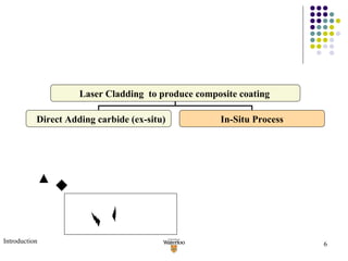
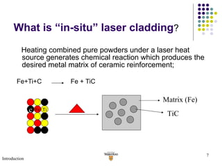
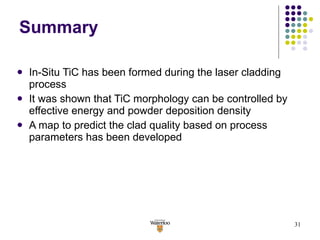
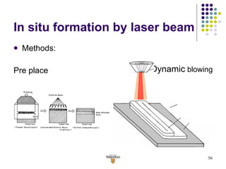
The document summarizes research on using laser cladding to produce an in-situ TiC-Fe composite coating on mild steel. Key findings include:
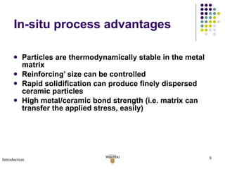
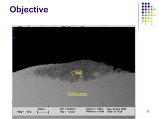
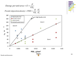
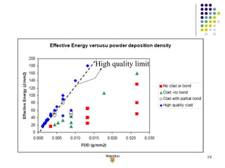
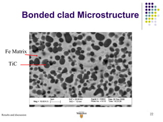
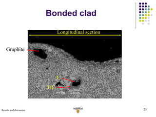
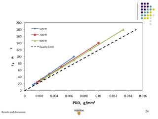
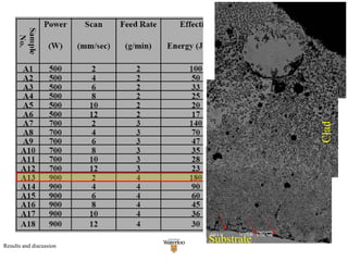
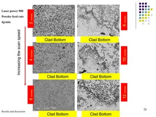
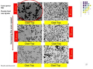
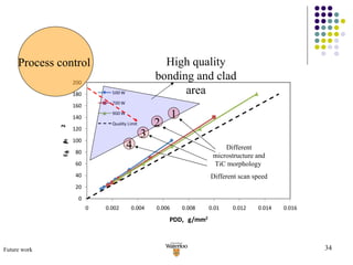
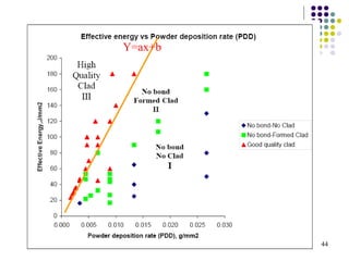
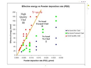
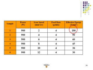
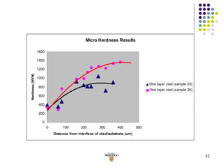
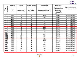
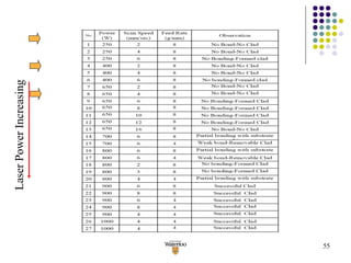
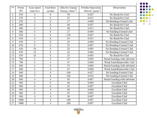
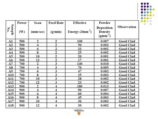
1) High quality coatings with complete metallurgical bonding between the clad and substrate were produced without porosity or cracks by optimizing laser processing parameters like power, scan speed, and powder feed rate.
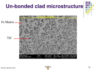
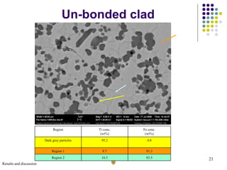
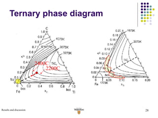
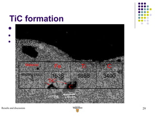
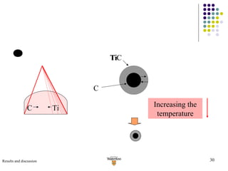
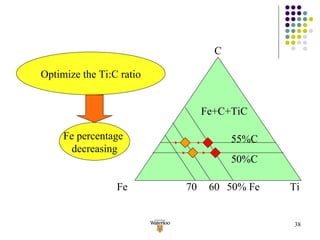
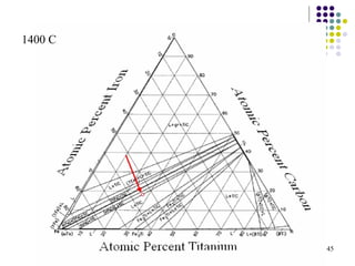
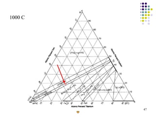
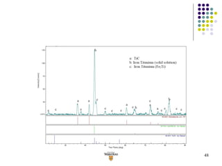
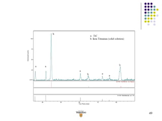
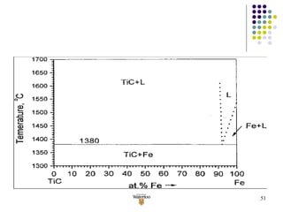
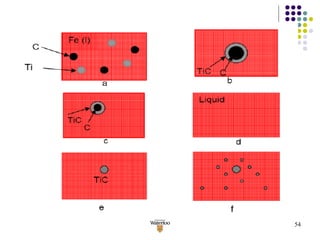
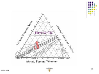
2) The microstructure and TiC morphology within the clad layer could be controlled by varying the processing conditions.
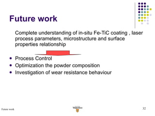
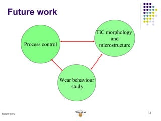
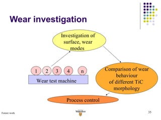
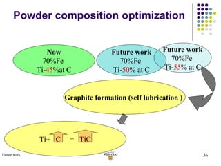
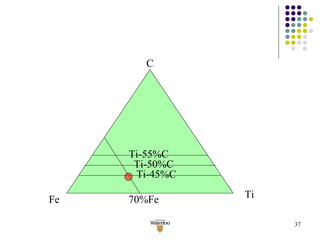
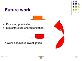
3) Future work is proposed to further optimize the process parameters, coating compositions, and investigate the relationship between microstructure and wear resistance properties.