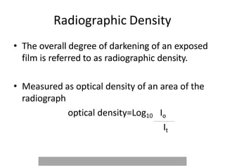
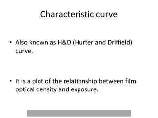
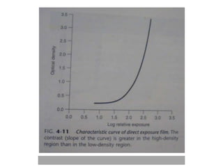
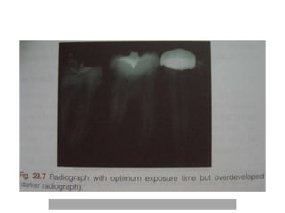
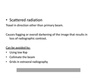
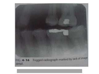
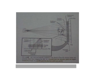
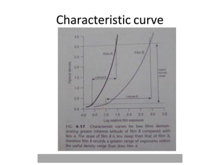
IDEAL RADIOGRAPH
Dr Megha Bahal Kakkar
Senior resident
Oral Medicine and Radiology
An ideal radiograph
• ‘An ideal radiograph is one which has the
desired density and overall degree of darkness
and which shows the part completely without
distortion and with maximum details and has
the right amount of contrast to make the
details fully apparent.’
-H.M. Worth
Imaging characteristics of x-ray film
• Radiographic density
• Radiographic contrast
• Radiographic speed
• Film Latitude
• Radiographic noise
• Radiographic blurring
• Image quality
Radiographic Density
• The overall degree of darkening of an exposed
film is referred to as radiographic density.
• Measured as optical density of an area of the
radiograph
optical density=Log10 Io
It
Characteristic curve
• Also known as H&D (Hurter and Driffield)
curve.
• It is a plot of the relationship between film
optical density and exposure.
• Gross fog or base plus fog.
• Optical density-0.2-0.3
Radiographic density is influenced by-
• Exposure
• Subject thickness
• Subject density
Exposure-
• film density is increased by-
• ing- mA, Kvp, exposure time
• ing the distance between the focal spot and film
• Subject thickness
Thicker the subject more beam attenuated
Exposure factors to be varied according to the size of
the patient.
• Subject Density
• Greater the density of an object within the subject
greater the attenuation
• Oral cavity-enamel, dentin and cementum, bone,
muscle, fat and air.
Beam
differentially attenuated by these absorbers
resultant beam
recorded as light and dark areas on film
Radiographic contrast
• It is described as the range of densities on a
radiograph
• It is defined as the difference in densities
between light and dark regions on a radiograph.
• High contrast –short grey scale of contrast
• Low contrast-long grey scale of contrast
Radiographic contrast of an image is
an interplay of -
• Subject contrast
• Film contrast
• Scattered radiation
• Subject contrast- is the range of characteristics
of the subject that influence the radiographic
contrast.
• Influenced by- subject thickness
subject density
atomic number
• Also influenced by-
• Beam energy and intensity
• time and mA of the exposure
Film contrast-
describes the capacity of radiographic films to display
differences in subject contrast , that is, variation in
the intensity of the remnant beam
- high contrast and low contrast films-high contrast
films reveals areas of small differences in subject
contrast more clearly.
-Film processing
-improper handling
-film fog
Characteristic curve
• Scattered radiation
Travel in direction other than primary beam.
Causes fogging or overall darkening of the image that results in
loss of radiographic contrast.
Can be avoided by-
• Using low Kvp
• Collimate the beam
• Grids in extraoral radiography
Radiographic speed
• It refers to the amount of radiation required to
produce an image of a standard density.
• Film speed is expressed as the reciprocal of
the exposure (in roentgen)required to
produce an optical density of 1 above gross
fog.
• Fast films –needs lower exposure than slow
films to produce a density of 1.
• Film speed controlled by silver halide grain
size and their silver content
• Ultra-speed film-group D
• Kodak insight-group E and F
Film Latitude
• It is the range of exposures that can be
recorded as distinguishable densities on a
film.
• Film with wide latitude records wide range of
subject contrast.
Characteristic curve
Radiographic noise
• It is the appearance of uneven density of a
uniformly exposed radiographic film.
• Causes-Radiographic mottle
Radiographic artifact
• Radiographic mottle-
• Uneven density resulting from the physical
structure of the film or intensifying screen.
Two important causes-
• Quantum mottle-czed by fluctuation in the no. of photons per unit
of the beam cross-sectional area absorbed by the intensifying
screen.
• Screen structure mottle-czed by screen phosphors.
(Fast screens-large crystals used)
Radiographic Blurring
• Sharpness
• Resolution
line –pairs per mm
Line-pairs
Radiographic blurring is caused by-
• Image receptor blurring
• Motion blurring
• Geometric blurring
Image receptor blurring
• Intra-oral films-grain size
• Intensifying screens
• Double emulsion film
•Motion blurring-
film
Subject
X-ray source
• Geometric blurring
Image Quality
• It describes the subjective judgement by the overall
appearance of the radiograph. It combines the features of
density,contrast,latitude ,sharpness,resolution and other
parameters.
• The Detective quantum efficiency(DQE) is a basic measure of
the efficiency of an imaging system.It encompasses image
contrast ,blur,speed and noise
THANK YOU

IDEAL RADIOGRAPH 1.pptx

  • 1.
    IDEAL RADIOGRAPH Dr MeghaBahal Kakkar Senior resident Oral Medicine and Radiology
  • 13.
    An ideal radiograph •‘An ideal radiograph is one which has the desired density and overall degree of darkness and which shows the part completely without distortion and with maximum details and has the right amount of contrast to make the details fully apparent.’ -H.M. Worth
  • 14.
    Imaging characteristics ofx-ray film • Radiographic density • Radiographic contrast • Radiographic speed • Film Latitude • Radiographic noise • Radiographic blurring • Image quality
  • 15.
    Radiographic Density • Theoverall degree of darkening of an exposed film is referred to as radiographic density. • Measured as optical density of an area of the radiograph optical density=Log10 Io It
  • 16.
    Characteristic curve • Alsoknown as H&D (Hurter and Driffield) curve. • It is a plot of the relationship between film optical density and exposure.
  • 18.
    • Gross fogor base plus fog. • Optical density-0.2-0.3
  • 19.
    Radiographic density isinfluenced by- • Exposure • Subject thickness • Subject density
  • 20.
    Exposure- • film densityis increased by- • ing- mA, Kvp, exposure time • ing the distance between the focal spot and film
  • 21.
    • Subject thickness Thickerthe subject more beam attenuated Exposure factors to be varied according to the size of the patient.
  • 22.
    • Subject Density •Greater the density of an object within the subject greater the attenuation • Oral cavity-enamel, dentin and cementum, bone, muscle, fat and air.
  • 23.
    Beam differentially attenuated bythese absorbers resultant beam recorded as light and dark areas on film
  • 24.
    Radiographic contrast • Itis described as the range of densities on a radiograph • It is defined as the difference in densities between light and dark regions on a radiograph. • High contrast –short grey scale of contrast • Low contrast-long grey scale of contrast
  • 25.
    Radiographic contrast ofan image is an interplay of - • Subject contrast • Film contrast • Scattered radiation
  • 26.
    • Subject contrast-is the range of characteristics of the subject that influence the radiographic contrast. • Influenced by- subject thickness subject density atomic number
  • 27.
    • Also influencedby- • Beam energy and intensity • time and mA of the exposure
  • 29.
    Film contrast- describes thecapacity of radiographic films to display differences in subject contrast , that is, variation in the intensity of the remnant beam - high contrast and low contrast films-high contrast films reveals areas of small differences in subject contrast more clearly. -Film processing -improper handling -film fog
  • 30.
  • 34.
    • Scattered radiation Travelin direction other than primary beam. Causes fogging or overall darkening of the image that results in loss of radiographic contrast. Can be avoided by- • Using low Kvp • Collimate the beam • Grids in extraoral radiography
  • 37.
    Radiographic speed • Itrefers to the amount of radiation required to produce an image of a standard density. • Film speed is expressed as the reciprocal of the exposure (in roentgen)required to produce an optical density of 1 above gross fog.
  • 38.
    • Fast films–needs lower exposure than slow films to produce a density of 1. • Film speed controlled by silver halide grain size and their silver content • Ultra-speed film-group D • Kodak insight-group E and F
  • 40.
    Film Latitude • Itis the range of exposures that can be recorded as distinguishable densities on a film. • Film with wide latitude records wide range of subject contrast.
  • 41.
  • 42.
    Radiographic noise • Itis the appearance of uneven density of a uniformly exposed radiographic film. • Causes-Radiographic mottle Radiographic artifact
  • 46.
    • Radiographic mottle- •Uneven density resulting from the physical structure of the film or intensifying screen. Two important causes- • Quantum mottle-czed by fluctuation in the no. of photons per unit of the beam cross-sectional area absorbed by the intensifying screen. • Screen structure mottle-czed by screen phosphors. (Fast screens-large crystals used)
  • 47.
    Radiographic Blurring • Sharpness •Resolution line –pairs per mm
  • 48.
  • 49.
    Radiographic blurring iscaused by- • Image receptor blurring • Motion blurring • Geometric blurring
  • 50.
    Image receptor blurring •Intra-oral films-grain size • Intensifying screens • Double emulsion film
  • 53.
  • 58.
    Image Quality • Itdescribes the subjective judgement by the overall appearance of the radiograph. It combines the features of density,contrast,latitude ,sharpness,resolution and other parameters. • The Detective quantum efficiency(DQE) is a basic measure of the efficiency of an imaging system.It encompasses image contrast ,blur,speed and noise
  • 59.