Downloaded 45 times

![Modelling And Analysis Of Hybrid Composite Joint Using Fem In Ansys
| IJMER | ISSN: 2249–6645 | www.ijmer.com | Vol. 4 | Iss. 6| June. 2014 | 42|
Figure 2. First Cast Iron Bridge in Shropshire
This mode of construction was the only one known to the designer, and is closely based on the design
of timber structures. The only concession to the new structural material was in the use of large scale, single
piece, curved members. Rolled bars of T- and L-sections did not become available until after Napoleonic wars
and the first I-beams, for light loading only, were made in Paris in 1847.
Heavy I-beams only become available in 1860 after the invention of mild steel. Fastening was
originally by slotting a circular cylinder, cast as an integral of the beam, over a cylindrical column, cast with a
retaining lip, but fish platesand bolting were introduced at early stage.
Steel “nailing” was developed and primarily used for fastening sheet metal to structural steel for metal
roof decks and claddings. Research undertaken at the University of Toronto has shown that the existing
technology of steel nailing also can be used to connect structural steelwork, particularly hollow structural
section steel members. Cold-formed structural members may be joined with bolted connections that are
designed with the aid of applicable national design standards, such as American Iron and Steel Institute (AISI).
Winter categorized the failure of bolted connections into four separate modes, described as end tear-out,
bearing, net-section fracture, and bolt shear. Recently Rogers and Hancock found AISI specification cannot be
used to accurately predict the failure modes of thin cold-formed sheet-steel bolted connections that are loaded in
shear. It is sometimes necessary to use combination (hybrid) joints in steel construction.
For example, high-strength bolts can be used in combination with welds, or rivets can be used in
combination with bolts. The need for a hybrid joint can rise for number different reasons. For example, the load
demands on an existing bolted joint may change with time, necessitating renovation of that joint. If the
geometry does not permit the addition of more bolts, welds can be added to the connection in order to increase
its capacity. Bonded structures can be of two types based on purely adhesive or adhesive/mechanical
connections. These types of connections include bonded-welded, bonded-riveted, and bonded-screwed
connections.
The concept hybrid joint is also used in structural timber by injecting a resin into the gap between the
connector and the wood to improve the performance of bolted and dowelled joints.
On the other hand, steel bolts/screws were used as shear connectors to joint steel/timber beam to
concrete slab [10-12]. Elshafie also used concrete shear key (dovetail) as shear connectors in timber-concrete
composite joints. It is convenient now to define an adhesive as a polymeric material which, when applied to
surfaces, can join them together and resist separation. The structural members of the joint, which are joined
together by the adhesive, are the adherends, a word first used by de Bruyne in 1939.
Fracture mechanics has become a very popular tool for characterization of adhesive metal joints in
recent years. Furthermore, Conrad et al. studied the effect of droplet diameter and droplet spacing on mode I
fracture toughness of a discontinuous wood-adhesive bonds. The fracture mechanics concept is also used to
understand the basic dentin adhesion mechanisms.
Advanced composite materials and structures have undergone rapid development over the past four
decades. The majority of advanced composite materials are filamentary with continuous fibers. As such, their](https://image.slidesharecdn.com/ijmer-46014146-140714061356-phpapp01/85/Modelling-and-Analysis-of-Hybrid-Composite-Joint-Using-Fem-in-ANSYS-2-320.jpg)
![Modelling And Analysis Of Hybrid Composite Joint Using Fem In Ansys
| IJMER | ISSN: 2249–6645 | www.ijmer.com | Vol. 4 | Iss. 6| June. 2014 | 43|
behavior and the behavior of structures made from them are more complicated than that of monolithic materials
and their structures.
Advanced composite materials can be divided into classes in various manners. One simple
classification scheme is to separate them according to the reinforcement forms- particulate-reinforced, fiber-
reinforced, or laminarcomposites. Fiber-reinforced composites, can be further divided into those containing
discontinuous or continuous fibers. Polymers, ceramics, and metals are all used as matrix materials, depending
on the particular requirements. The matrix holds the fibers together in structural unit and protects them from
external damage, transfers and distributes the applied loads to the fibers, and in many cases contributes some
needed property such as ductility, toughness, or electrical insulation.
The structure of polymers consists of long molecules with a backbone of carbon atoms linked by
covalent bonds. In non-crystalline or amorphous polymers the molecular chains have an entirely random
orientation and are cross-linked occasionally by a few strong covalent bonds and numerous but weaker van der
Waals bonds. These weaker bonds break as the temperature reaches a value known as the glass transition
temperature, Tg
, characteristic for each polymer. Below Tg
the polymer behaves as a linear elastic solid.
Creep becomes increasingly significant as the temperature increases and, above Tg
, the polymer
deforms in a viscous manner under load. In crystalline polymers the molecules are oriented along preferred
directions, bringing with them optical and mechanical anisotropy. Polymers are described as being either
thermosets (e.g., epoxy, polyester, SiC, SiN, ZrO), have a wide range of engineering applications.
The strong ionic and covalent nature of the bonding in most ceramics leads to a stable crystal structure
with a high melting point and high stiffness. Many ceramic materials have very high elastic moduli and
strengths, but the advantages of these properties bestow are often outweighed by their highly brittle nature,
which leads to low and unpredictable failure stress resulting from the presence of flaws.
Metal matrix composites typically comprise a light metallic alloy matrix, usually based on aluminum,
magnesium or titanium alloys. The major reinforcing elements used in composites are glass, carbon/graphite,
organic, and ceramic.
Both metal and ceramic materials have properties closer to those of likely reinforcements and this
leads to a different choice of properties for which these composite systems are optimized.
With polymer matrix composites, it is almost true to say that the properties of the composite are
essentially those of the fibers, with little contribution from the properties of the matrix. phenolic) or
thermoplastics (e.g., polyimide, polysulfone, polyetheretherketone, polyphenylenesulfide). Ceramics, such as
glasses, cement & concrete, and engineering ceramics(Al2
O3).
FiberReinforced Polymer (FRP), earlier limited to aerospace structures, are gaining acceptance in civil
engineering applications also. FRP plates, sheets, rebar, and strands have been increasingly used in the
construction industry due to their superior properties.
One of the potential structural applications of FRP composites with concrete or steel structures is
strengthening of RC or steel beams with unidirectional fiber-composite sheets/plates bonded on their tension
faces via the use of epoxy adhesives.
Growing maintenance and durability problems in transportation infrastructure have led researchers to
explore FRP box-girder, I-beam, or other shapes in bridges. There are numerous examples of completed all-
composite new bridges and several more are under construction.
Due to the relatively low weight and high strength of FRP girders and decks it has proven to be
efficient to replace old bridges that no longer meet today’s requirements with FRP alternatives. While design
concepts vary, several systems employ a modular system to build up the bridge deck, meaning that composite
profiles are transversely joined to form the required bridge span or occasionally width. Kumar et al. installed an
all-composite bridge deck made up of FRP.
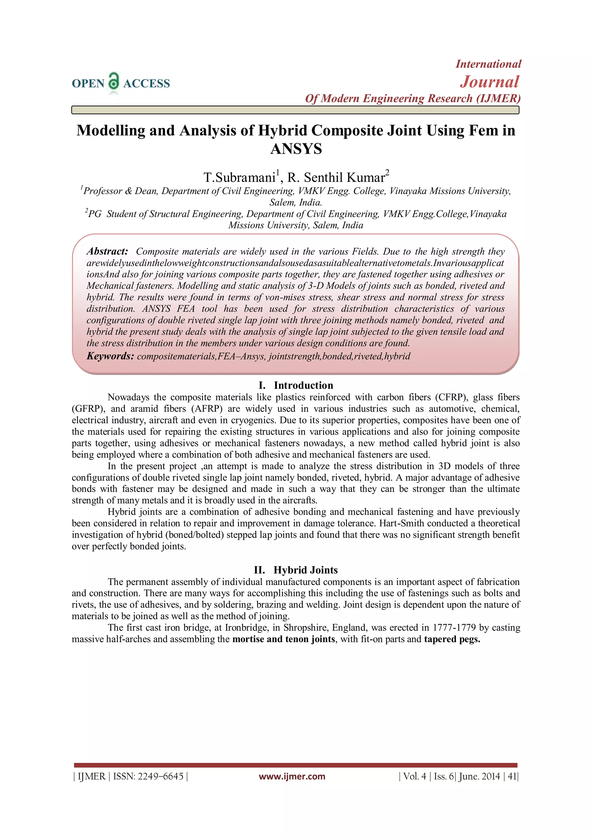
. III. Snap Joint in Composite Structures
In the majority of the composite structural components, both bolted and/or adhesive bonded joint was
used. Most of the details are similar to those for metal joints. It was shown from extensive testing on bolted
composite joints that failure always occurs in a catastrophic manner due to high stress concentration developed
at the bolt locations.
Due to the inherent low bearing and interlaminar shear strengths of composites, these stress
concentrations threaten the downfall of every piece of the composite structure [86-87]. The optimum composite
joint design is the one capable of distributing stresses over a wide area rather than to concentrate them at a
point. Adhesively bonded joints can satisfy these requirements, however, most of the adhesives are brittle, and
brittle failure is unavoidable. This was the motivation of developing what is called the SNAP joint.](https://image.slidesharecdn.com/ijmer-46014146-140714061356-phpapp01/85/Modelling-and-Analysis-of-Hybrid-Composite-Joint-Using-Fem-in-ANSYS-3-320.jpg)
![Modelling And Analysis Of Hybrid Composite Joint Using Fem In Ansys
| IJMER | ISSN: 2249–6645 | www.ijmer.com | Vol. 4 | Iss. 6| June. 2014 | 45|
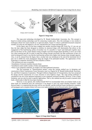
IV. Hybrid Joints
In an attempt to improve the joint strength of composite materials, a hybrid of adhesive and bolted
joints has also been explored [88], Fig. 5-1. Hybrid joints failed at a higher load than the bolted joints and with
the proper clamping torque reached the same failure load as the adhesive joints.
Furthermore, unlike the adhesive joints, hybrid joints failed in two steps, first by initiation of fiber tear
(akin to delamination in laminated continuous fiber composites) at one of the lap ends and then by tensile
failure across the bolt hole. This led to a slightly higher overall elongation at failure for specimens with the
hybrid joints.
Failure in fatigue also started by fiber tear and when the fiber tear progressed to the bolted area, a
combination of half-net-tension failure and splitting (cleavage failure) occurred. In both static as well fatigue,
failure was initiated by fiber tear and the round washers with their edges located slightly away from the lap ends
were not effective in preventing fiber tear.
Hybrid joints give better static as well as fatigue performance than adhesive joints in composites when
fibertear, the primary failure mode in adhesive joints, is either prevented or delayed by the presence of
clamping. The presence of the lateral clamping pressure can significantly decrease the maximum peel stress at
the interface, which helps in achieving improved joint performance. The square washer representing full
clamping to the edges of the overlap area gives a better performance compared to round washer, representing
partial clamping.
In an attempt to improve the joint strength of composite materials, a hybrid of adhesive and bolted
joints has also been explored, Fig. 5-1. Hybrid joints failed at a higher load than the bolted joints and with the
proper clamping torque reached the same failure load as the adhesive joints. Furthermore, unlike the adhesive
joints, hybrid joints failed in two steps, first by initiation of fiber tear (akin to delamination in laminated
continuous fiber composites) at one of the lap ends and then by tensile failure across the bolt hole.
This led to a slightly higher overall elongation at failure for specimens with the hybrid joints. Failure in
fatigue also started by fiber tear and when the fiber tear progressed to the bolted area, a combination of half-net-
tension failure and splitting (cleavage failure) occurred. In both static as well fatigue, failure was initiated by
fiber tear and the round washers with their edges located slightly away from the lap ends were not effective in
preventing fiber tear.
Fu and Mallick found that, hybrid joints give better static as well as fatigue performance than adhesive
joints in structural reaction injection molded composites when fiber tear, the primary failure mode in adhesive
joints, is either prevented or delayed by the presence of clamping. Their finite element analyses proved that the
presence of the lateral clamping pressure can significantly decrease the maximum peel stress at the interface,
which helps in achieving improved joint performance.
Figure 4 Sketch of an Adhesive/Bolted (Hybrid) Joint
V. Conclusion
In this analysis, FEA for the prediction of stress distribute on in bonded, riveted and hybrid joints
have been carried out 3D models were created by using PROE (creoparametric) and analyzed using ANSYS
workbench FEA software .shear stress was used to compared the results with three joining methods. The shear
stress with hybrid joint has less value of stress and also the carbon Fiber reinforced plastic is more strength than
any other composite material. The stress induced by using ANSYS is less than the material ultimate stress and
ultimate limit. The total deformation for both the materials in hybrid joint is less. It was found that a well
designed hybrid joint is very efficient when compared to bonded, riveted joints in case of repair situation in
aircraft fuselage panels, structures etc.](https://image.slidesharecdn.com/ijmer-46014146-140714061356-phpapp01/85/Modelling-and-Analysis-of-Hybrid-Composite-Joint-Using-Fem-in-ANSYS-5-320.jpg)
![Modelling And Analysis Of Hybrid Composite Joint Using Fem In Ansys
| IJMER | ISSN: 2249–6645 | www.ijmer.com | Vol. 4 | Iss. 6| June. 2014 | 46|
REFERENCES
[1]. Noah M. Salih1, Mahesh J. Patil 2, Hybrid (Bonded/Bolted) Composite Single-Lap Joints And Its Load Transfer
Analysis, International Journal of Advanced Engineering Technology E-ISSN 0976-3945 IJAET/Vol.III/ Issue
I/January-March, 2012/213-216.
[2]. Ch. Aswini Kumar1, G. Pattabhi2, S.Santosh3, I. Bhanu Latha4, Analysis of Adhesively Bonded Double Lap Joint in
Laminated FRP Composites Subjected To Longitudinal Loading, international journal of engineering science &
advanced technology volume-2, issue-2, 307 – 316 ijesat | Mar-Apr 2012.
[3]. Vincentcaccesse, Richard newer, until s. vel detection of bolt load loss in hybrid composite.metal bolted connections
elseiver engineering structures 26(2004) 895-906.
[4]. W. Hufenbach a, L.A. Dobrzański b, M. Gude a, J. Konieczny b, A. Czulak a, Optimisation of the rivet joints of the
CFRP Composite material and aluminum alloy, Journal of Achievements in Materials and Manufacturing
Engineering, volume 20 issues 1-2 January-February 2007.
[5]. M.A. McCarthy*, C.T. McCarthy, Finite Element Analysis Of The Effects Of clearance On Single-Shear, Composite
Bolted Joints, Journal of Plastics, Rubber and Composites, The Institute of Materials, London, UK, Vol. 32, No. 2,
in-press.
[6]. Proceedings of the “National Conference on Emerging Trends In Mechanical Engineering 2k13” 122 NCETIME –
2k13 Design Of Hybrid Composite Joints For Research Area S. Lokesha and H. Mohitaa Student, Refrigeration and
Air Conditioning Division, Department of Mechanical Engineering, College of Engineering, Anna University,
Chennai-28.](https://image.slidesharecdn.com/ijmer-46014146-140714061356-phpapp01/85/Modelling-and-Analysis-of-Hybrid-Composite-Joint-Using-Fem-in-ANSYS-6-320.jpg)

The document discusses the modeling and analysis of hybrid composite joints using Finite Element Method (FEM) in ANSYS, focusing on various configurations including bonded, riveted, and hybrid joints. It highlights the advantages of hybrid joints that combine adhesive bonding with mechanical fastening, emphasizing their improved performance in structural applications compared to traditional methods. The study presents results on stress distribution characteristics and the effects of different joining techniques on joint strength and failure modes.


