Download to read offline
![International Journal of Engineering and Technical Research (IJETR)
ISSN: 2321-0869, Volume-1, Issue-10, December 2013
38 www.erpublication.org
Abstract— Machining of composite materials is difficult to
carry out due to the anisotropic and nonhomogeneous structure
of composites and to the high abrasiveness of their reinforcing
constituents. This typically results in damage being introduced
into the work piece and very rapid wear development in the
cutting tool. Conventional machining processes such as turning,
drilling or milling can be adapted to composite materials,
provided proper tool design and operating conditions are
maintained.
The present work also describes the machining (drilling) of
GFRP composites with the help of Step drill of three sets, with
three different speeds. Results revealed that 8-4 mm step drill
showed better machining characteristic than the other two 12-8
mm and 10-6 mm step drills. The ZnS Filled GFRP composites
had better performance than TiO2 filled GFRP Composites.
Index Terms— Drilling; Polymer-matrix composites; Thrust
force; Delamination.
I. INTRODUCTION
Fiber reinforced plastics have been widely used for
manufacturing aircraft and spacecraft structural parts because
of their particular mechanical and physical properties such as
high specific strength and high specific stiffness. Another
relevant application for fiber reinforced polymeric
composites (especially glass fiber reinforced plastics) is in the
electronic industry, in which they are employed for producing
printed wiring boards. Drilling of these composite materials
irrespective of the application area, can be considered as a
critical operation owing to their tendency to delaminate when
subjected to mechanical stresses. With regard to the quality of
machined component, the principal drawbacks are related to
surface delamination, fiber/resin pullout and inadequate
surface smoothness of the hole wall. Among the defects
caused by drilling, delamination appears to be the most
critical [1] Figure 1 shows that the factors such as cutting
parameters and tool geometry/material must be carefully
selected aiming to obtain best performance on the drilling
operation, i.e., to obtain best hole quality, which represents
minimal damage to the machined component and satisfactory
machined surface.
Composite materials are constituted of two phases: the matrix,
which is continuous and surrounds the other phase, often
called as reinforcing phase [3]. Epoxy resins are widely used
as matrix in many fibre reinforced composites; they are a class
of thermoset materials of particular interest to structural
engineers owing to the fact that they provide a unique balance
of chemical and mechanical properties combined with wide
Manuscript received December 09, 2013.
Patil Deogonda B, Assistance Professor, Dept. of Mechanical
Engineering. SMSMPITR, Akluj
Vijaykumar N Chalwa, Dean R&D, Dept. of Mechanical. Engineering.
SMSMPITR, Akluj.
processing versatility [4]. Within reinforcing materials, glass
fibres are the most frequently used in structural constructions
because of their specific strength properties [3]. The present
study focuses on machinability study of GFRP laminated
composites with filler material Tio2 and graphite and
evaluation of thrust force, delamination factor for two drill
diameters at different speeds
Figure:-1. Principal aspects to be considered when drilling
fiber reinforced plastics
II. MACHINING OF COMPOSITE MATERIALS
The machining of GFRP is quite different from that of
metals and results in many undesirable effects such as rapid
tool wear, rough surface finish and defective subsurface
layers caused by cracks and delamination. At the beginning of
drilling operation, the thickness of the laminated composite
material is able to withstand the cutting force and as the tool
approaches the exit plane, the stiffness provided by the
remaining plies may not be enough to bear the cutting force,
causing the laminate to separate resulting in delamination.
The delamination that occur during drilling severely influence
the mechanical characteristics of the material around the hole.
In order to avoid these problems, it is necessary to determine
the optimum conditions for a particular machining operation.
Drilling is a particularly critical operation for fiber reinforced
plastics (FRP) laminates because the great concentrated
forces generated can lead to widespread damage. The major
damage is certainly the delamination that can occur both on
the entrance and exit sides of the work piece [4]. The
delamination on the exit surface, generally referred to as push
down delamination, is more extensive, and is considered more
severe. Hocheng and Tsao have beautifully explained the
causes and mechanisms of formation of these push down
delamination and they have also reasoned out the dependence
of extent of delamination on the feed rate [5]. In earlier
studies it has been observed that the extent of delamination is
related to the thrust force, feed, material properties and speed,
etc. and that there is a critical value of the thrust force
(dependent on the type of material drilled) below which the
delamination is negligible [6].
Machining of Glass Fiber Reinforcement Epoxy
Composite
Patil Deogonda B, Vijaykumar N Chalwa](https://image.slidesharecdn.com/ijetr012018-171119123853/85/Ijetr012018-1-320.jpg)
![International Journal of Engineering and Technical Research (IJETR)
ISSN: 2321-0869, Volume-1, Issue-10, December 2013
38 www.erpublication.org
Abstract— Machining of composite materials is difficult to
carry out due to the anisotropic and nonhomogeneous structure
of composites and to the high abrasiveness of their reinforcing
constituents. This typically results in damage being introduced
into the work piece and very rapid wear development in the
cutting tool. Conventional machining processes such as turning,
drilling or milling can be adapted to composite materials,
provided proper tool design and operating conditions are
maintained.
The present work also describes the machining (drilling) of
GFRP composites with the help of Step drill of three sets, with
three different speeds. Results revealed that 8-4 mm step drill
showed better machining characteristic than the other two 12-8
mm and 10-6 mm step drills. The ZnS Filled GFRP composites
had better performance than TiO2 filled GFRP Composites.
Index Terms— Drilling; Polymer-matrix composites; Thrust
force; Delamination.
I. INTRODUCTION
Fiber reinforced plastics have been widely used for
manufacturing aircraft and spacecraft structural parts because
of their particular mechanical and physical properties such as
high specific strength and high specific stiffness. Another
relevant application for fiber reinforced polymeric
composites (especially glass fiber reinforced plastics) is in the
electronic industry, in which they are employed for producing
printed wiring boards. Drilling of these composite materials
irrespective of the application area, can be considered as a
critical operation owing to their tendency to delaminate when
subjected to mechanical stresses. With regard to the quality of
machined component, the principal drawbacks are related to
surface delamination, fiber/resin pullout and inadequate
surface smoothness of the hole wall. Among the defects
caused by drilling, delamination appears to be the most
critical [1] Figure 1 shows that the factors such as cutting
parameters and tool geometry/material must be carefully
selected aiming to obtain best performance on the drilling
operation, i.e., to obtain best hole quality, which represents
minimal damage to the machined component and satisfactory
machined surface.
Composite materials are constituted of two phases: the matrix,
which is continuous and surrounds the other phase, often
called as reinforcing phase [3]. Epoxy resins are widely used
as matrix in many fibre reinforced composites; they are a class
of thermoset materials of particular interest to structural
engineers owing to the fact that they provide a unique balance
of chemical and mechanical properties combined with wide
Manuscript received December 09, 2013.
Patil Deogonda B, Assistance Professor, Dept. of Mechanical
Engineering. SMSMPITR, Akluj
Vijaykumar N Chalwa, Dean R&D, Dept. of Mechanical. Engineering.
SMSMPITR, Akluj.
processing versatility [4]. Within reinforcing materials, glass
fibres are the most frequently used in structural constructions
because of their specific strength properties [3]. The present
study focuses on machinability study of GFRP laminated
composites with filler material Tio2 and graphite and
evaluation of thrust force, delamination factor for two drill
diameters at different speeds
Figure:-1. Principal aspects to be considered when drilling
fiber reinforced plastics
II. MACHINING OF COMPOSITE MATERIALS
The machining of GFRP is quite different from that of
metals and results in many undesirable effects such as rapid
tool wear, rough surface finish and defective subsurface
layers caused by cracks and delamination. At the beginning of
drilling operation, the thickness of the laminated composite
material is able to withstand the cutting force and as the tool
approaches the exit plane, the stiffness provided by the
remaining plies may not be enough to bear the cutting force,
causing the laminate to separate resulting in delamination.
The delamination that occur during drilling severely influence
the mechanical characteristics of the material around the hole.
In order to avoid these problems, it is necessary to determine
the optimum conditions for a particular machining operation.
Drilling is a particularly critical operation for fiber reinforced
plastics (FRP) laminates because the great concentrated
forces generated can lead to widespread damage. The major
damage is certainly the delamination that can occur both on
the entrance and exit sides of the work piece [4]. The
delamination on the exit surface, generally referred to as push
down delamination, is more extensive, and is considered more
severe. Hocheng and Tsao have beautifully explained the
causes and mechanisms of formation of these push down
delamination and they have also reasoned out the dependence
of extent of delamination on the feed rate [5]. In earlier
studies it has been observed that the extent of delamination is
related to the thrust force, feed, material properties and speed,
etc. and that there is a critical value of the thrust force
(dependent on the type of material drilled) below which the
delamination is negligible [6].
Machining of Glass Fiber Reinforcement Epoxy
Composite
Patil Deogonda B, Vijaykumar N Chalwa](https://image.slidesharecdn.com/ijetr012018-171119123853/75/Ijetr012018-1-2048.jpg)
![Machining of Glass Fiber Reinforcement Epoxy Composite
41 www.erpublication.org
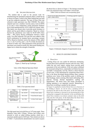
Figure:-9.Delamination at the twist drill entrance (left) and
exit (right) when drilling laminates.
Figure:-10.Comparison of delamination factor against drilling
speed, feed and drill geometry for Tio2 and Zns filled GFRP
Composite.
Figure:-11. Comparison of delamination factor against
drilling speed, feed and drill geometry for Unfiled filled
GFRP.
•Delamination factor decrease as speed increases for all the
drill dia.
•12-8mm step drill shows higher damage factor fallowed by
10-6mm and 8-4mm step drill.
•As the filler percentage increased from 1% to 3% for TiO2
and 1% to 3% for ZnS the delamination factor values are less
at all the speeds and has shown downward trend.
•Unfilled composite has shown more damage factor when
compared to filled composites (TiO2 and ZnS).
•ZnS Filled composite has shown less damage factor than
TiO2 filled composite.
VI. CONCLUSIONS
Based on the experimental results presented, the following
conclusions can be drawn:
Considerable efforts have been focused on the better
understanding of the phenomena associated with the cutting
mechanism. Conventional high speed steel twist drills are
used for drilling operation abrasion, was the principal wear
mechanism and led to the elevation of the thrust force. The
increasing of thrust force as a result of increasing drill
pre-wear leads to destroying the matrix and micro-cracking at
the ply interfaces, which deteriorates the surface finish. The
principal factors used to evaluate the performance of the
process are undoubtedly the damage caused at the drill entry
or exit of the hole produced. The damage decreases with
cutting parameters, which means that the composite damage is
smaller for higher cutting speed within the cutting range
tested. Delamination decreases as the spindle speed is
elevated, probably owing to the fact that the cutting
temperature is elevated with spindle speed, thus promoting
the softening of the matrix and inducing less delamination.
The effect of addition of filler material like TiO2 and ZnS have
shown that higher the percentage higher the values of thrust
and lesser delamination factor, which insists that the better
bonding of the filler material with the fiber matrix have
increased the capacity of force sustainability.
REFERENCES
[1]. A.M. Abrao et.al,. Drilling of fiber reinforced plastics: A review, Journal
of Materials Processing](https://image.slidesharecdn.com/ijetr012018-171119123853/85/Ijetr012018-4-320.jpg)
![International Journal of Engineering and Technical Research (IJETR)
ISSN: 2321-0869, Volume-1, Issue-10, December 2013
42 www.erpublication.org
Technology 186 (2007) 1–7.
[2]. W.D. Callister, Materials Science and Engineering: An Introduction,
sixth ed., Wiley, Canada, 2002.
[3]. M.A. Boyle, C.J. Martin, J.D. Neuner, Epoxy resin, in: H. Hansmann
(Ed.), Composites Compendium, ASM Handbook FB MVU,
Werkstofftechnologien, Kunststofftechnik, 2003.
[4]. S. Jain, D.C.H. Yang, Delamination-free drilling of composite
laminates, Trans. ASME J. Eng. Ind. 116 (4) (1994) 475–481.
[5]. H. Hocheng, C.C. Tsao, Analysis of delamination in drilling composite
materials using core drill, Aust. J. Mech. Eng. 1 (1) (2003) 49–53.
[6]. H. Saghizadeh, C.K.H. Dharan, Delamination fracture toughness of
graphite and aramid epoxy composites, Trans. ASME J. Eng. Mater.
Technol. 108 (1986) 290–295.
[7]. Paulo Davim, J; et al: Experimental study of drilling glass fiber
reinforced plastics (GFRP) manufactured by hand lay-up, ‘Composites
Science and Technology’, vol. 64, 2004, 289-297.
[8]. Campos Rubio J; et al: Effects of high speed in the drilling of glass fibre
reinforced plastic: Evaluation of the delamination factor, 'International
Journal of Machine Tools & Manufacture’, vol. 48, 2008, 715- 720.
[9]. Abrao, AM; et al: The effect of cutting tool geometry on thrust force and
delamination when drilling glass fibre reinforced plastic composite,
'Materials and Design’, vol. 29, 2008, 508-513.
[10]. Mohan, NS; et al: Delamination analysis in drilling process of glass
fiber reinforced plastic (GFRP) composite materials, ’Journal of Materials
Processing Technology’, vol. 186, 2007, 265-271.
[11]. Paulo Davim, J; et al: Drilling fiber reinforced plastics (FRPs)
manufactured by hand lay-up: influence of matrix (Viapal VUP 9731 and
ATLAC 382-05), ‘Journal of Materials Processing Technology’, 155 –156,
2004, 1828–833.
[12]. Khashaba, UA; et. al: Machinability analysis in drilling woven
GFR/epoxy composites: Part II – Effect of drill, 'wear,’ Composites: Part A‘,
vol. 41, 2010, 1130–1137.
[13]. Hocheng, H; Tsao, CC: Effects of special drill bits on drilling-induced
delamination of composite materials, ’International Journal of Machine
Tools & Manufacture’, vol. 46, 2006, 1403–1416.
[14]. Khashaba, UA: Delamination in drilling GFR - thermoset composites,’
Composite Structures’, vol. 63, 2004, 313–327.
[15]. Hocheng, H; Tsao, CC: The path towards delamination-free drilling of
composite materials, 'Journal of Materials Processing Technology’, vol. 167,
2005, 251–264.
[16]. Hocheng, H; Tsao, CC: Effects of exit back-up on delamination in
drilling composite materials using a saw drill and a core drill, 'International
Journal of Machine Tools & Manufacture’, vol. 45, 2005, 1261–1270.
[17]. Chung - Chen Tsao; Wen - Chou Chen: Prediction of the location of
delamination in the drilling of composite laminates, ’Journal of Materials
Processing Technology’, vol. 70, 1997, 185-189.
[18].S. Basavarajappa;K.V.Arun; J Paulo Davim: Effect of Filler Materials
on Dry Sliding Wear Behavior of Polymer Matrix Composites – A Taguchi
Approach, Journal of Minerals & Materials Characterization & Engineering,
Vol. 8, No.5, pp 379-391, 2009.
PATIL DEVGONDA
I am completed BE degree and Master’s degree in Mechanical Engineering
from VTU, Karnataka in the year 2011 and 2013. Currently I am working as
an Assistance professor in Department of Mechanical Engineering at
SMSMPITR, Akluj, and Maharashtra State, India.
Vijaykumar N Chalwa
I am completed BE in Mechanical
Engineering at REC, Bhalki in the year 2009
from VTU and I got master degree in
Machine Design at BEC, Bagalkot in the
year 2011. Now I am working as a dean R&D
and Asst prof. in Mechanical Engineering
Department at SMSMPITR Akluj. I am
having three years’ teaching experience. And
I published eight international journal
papers.](https://image.slidesharecdn.com/ijetr012018-171119123853/85/Ijetr012018-5-320.jpg)

The document discusses the challenges of machining glass fiber reinforced plastics (GFRP) due to their anisotropic structure and high abrasiveness, focusing on drilling operations. It details an experimental study involving different drill sizes and speeds, revealing that a 8-4 mm step drill performed best, and that ZNS-filled GFRP composites showed superior results over TiO2-filled composites in terms of thrust force and delamination. Key findings include that increasing drill speed decreases thrust force and delamination, emphasizing the importance of optimized drilling parameters for improved machining quality.