Download to read offline
![http://www.iaeme.com/IJECET/index.asp 43 editor@iaeme.com
International Journal of Electronics and Communication Engineering & Technology
(IJECET)
Volume 6, Issue 10, Oct 2015, pp. 43-52, Article ID: IJECET_06_10_005
Available online at
http://www.iaeme.com/IJECETissues.asp?JType=IJECET&VType=6&IType=10
ISSN Print: 0976-6464 and ISSN Online: 0976-6472
© IAEME Publication
IMPLEMENTING 3D BASE STATION
SIMULATION IN LONG TERM EVOLUTION
TO LOCATE SUBSCRIBERS WITHIN A
NETWORK
Deepanjali Redhu and Abhishek Bhatnagar
Kurukshetra University Kurukshetra, Haryana
ABSTRACT
LTE is the natural upgrade path for carriers with both GSM/UMTS
networks and CDMA2000 networks. The different LTE frequencies and bands
used in different countries will mean that only multi-band phones will be able
to use LTE in all countries where it is supported. LTE is the natural upgrade
path for carriers with both GSM/UMTS networks and CDMA2000 networks.
The different LTE frequencies and bands used in different countries will mean
that only multi-band phones will be able to use LTE in all countries where it is
supported.
Cite this Article: Santosh Pandi P and S L Gangadharaiah. Implementing 3D
Base Station Simulation In Long Term Evolution To Locate Subscribers
within A Network, International Journal of Electronics and Communication
Engineering & Technology, 6(10), 2015, pp. 43-52.
http://www.iaeme.com/IJECET/issues.asp?JType=IJECET&VType=6&IType=
10
1. INTRODUCTION
LTE, an abbreviation for Long-Term Evolution, commonly marketed as 4G LTE, is
a standard for wireless communication of high-speed data for mobile phones and data
terminals. It is based on the GSM/EDGE and UMTS/HSPA network technologies,
increasing the capacity and speed using a different radio interface together with core
network improvements.[1][2]
The standard is developed by the 3GPP (3rd Generation
Partnership Project) and is specified in its Release 8 document series, with minor
enhancements described in Release 9.
LTE is the natural upgrade path for carriers with both GSM/UMTS networks and
CDMA2000 networks. The different LTE frequencies and bands used in different
countries will mean that only multi-band phones will be able to use LTE in all
countries where it is supported.](https://image.slidesharecdn.com/ijecet0610005-151105131542-lva1-app6891/85/Ijecet-06-10_005-1-320.jpg)
![Santosh Pandi P and S L Gangadharaiah
http://www.iaeme.com/IJECET/index.asp 44 editor@iaeme.com
Although marketed as a 4G wireless service, LTE (as specified in the 3GPP
Release 8 and 9 document series) does not satisfy the technical requirements the
3GPP consortium has adopted for its new LTE-Advanced standard. The requirements
were originally set forth by the ITU-R organization in its IMT-Advanced
specification. However, due to marketing pressures and the significant advancements
that WiMAX, HSPA+ and LTE bring to the original 3G technologies, ITU later
decided that LTE together with the aforementioned technologies can be called 4G
technologies.[3]
The LTE Advanced standard formally satisfies the ITU-R
requirements to be considered IMT-Advanced.[4]
To differentiate LTE Advanced and
WiMAX-Advanced from current 4G technologies, ITU has defined them as "True
4G".
2. AREA OF APPLICATION
The Third-Generation Partnership Project (3GPP) formed in 1998 acts as a standards-
developing body responsible for specifications of the Third Generation (3G)
Universal Terrestrial Radio Access (UTRA) and the Global System for Mobile
communications (GSM) standards. LTE is the natural upgrade path for carriers with
both GSM/UMTS networks and CDMA2000 networks. The different LTE
frequencies and bands used in different countries will mean that only multi-band
phones will be able to use LTE in all countries where it is supported.
The 3GPP intends LTE to be a fourth generation (4G) mobile-communication
system that can take the telecom industry into the 2020s. In June 2005, a study item
by the project finalized the requirements for LTE to ensure competiveness over a ten-
year time frame. The requirements include reduced delays in terms of connection and
transmission latency, increased user data rates, reduced cost per bit through improved
spectral efficiency, and greater flexibility of spectrum usage in both new and pre-
existing bands. Other key requirements involve simplified network architecture,
reasonable power consumption for the mobile terminal, and seamless mobility,
including between different radio-access technologies.
Release 8 of 3GPP standards provided enhancements to the existing Universal
Mobile Telecommunications System (UMTS) with the specifications for LTE and the
System Architecture Evolution (SAE). SAE represents the non-radio aspects of the
complete LTE system and focuses on the end goal of a packet-switched core to
support packet-switched radio access. This flat IP-based network architecture ensures
mobility between existing mobile telecommunication systems (e.g., GSM, UTRAN,
Wi-Fi, and WiMAX) and replaces the General Packet Radio Service (GPRS) core
network for 2G and Wideband Code Division Multiple Access (WCDMA)-based 3G
networks.
3. OBJECTIVE
The ability to locate subscribers within a network remains a key element in past and
future mobile telecommunication services. From an operational perspective, a mobile
network would not be “mobile” if the location between subscriber stations (SS),
which is synonymous with mobile stations (MS), and base stations (BS) could not
identify its initial location followed by constant updating while the SS is on the move.
This necessary functionality facilitates the success of location-based applications
on cellular phones. Consumers use their mobile devices for navigation, weather
information, traffic status and social-networking features such as identifying friends](https://image.slidesharecdn.com/ijecet0610005-151105131542-lva1-app6891/85/Ijecet-06-10_005-2-320.jpg)


![Implementing 3D Base Station Simulation In Long Term Evolution To Locate Subscribers
within A Network
http://www.iaeme.com/IJECET/index.asp 47 editor@iaeme.com
% Find x-variable coefficients
a11 = (siteX(2)-siteX(1))^2;
a21 = (siteX(3)-siteX(1))^2;
% Find y-variable coefficients
a12 = (siteY(2)-siteY(1))^2;
a22 = (siteY(3)-siteY(1))^2;
% Find z-variable coefficients
a13 = (siteZ(2)-siteZ(1))^2;
a23 = (siteZ(3)-siteZ(1))^2;
% Find values for B-matrix
b1 = siteRad(1)^2-siteRad(2)^2-siteX(1)^2+siteX(2)^2-...
siteY(1)^2+siteY(2)^2-siteZ(1)^2+siteZ(2)^2;
b2 = siteRad(1)^2-siteRad(3)^2-siteX(1)^2+siteX(3)^2-...
siteY(1)^2+siteY(3)^2-siteZ(1)^2+siteZ(3)^2;
% Coefficient Matrix A
A = [a11 a12 a13; a21 a22 a23];
% Matrix B
B = [b1; b2];
% Find solutions to x, y, and z
X=AB;
interX(h)=X(1);
interY(h)=X(2);
interZ(h)=X(3);
approxX=mean(interX);
approxY=mean(interY);
approxZ=mean(interZ);
decp(h)=sqrt(approxX^2+approxY^2+approxZ^2);
end
% Mean estimate position error per simulation
averagePositionError(N)=mean(decp);
% Standard Deviation of Error
stDevPositionError(N)=std(decp);
% Mean Radial Spherical Error per simulation
stdX = std(interX);
stdY = std(interY);
stdZ = std(interZ);
MRSE(N)= sqrt(stdX^2+stdY^2+stdZ^2);
numSim(N) = N;
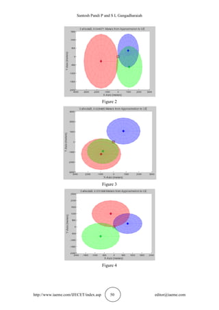
% Plot](https://image.slidesharecdn.com/ijecet0610005-151105131542-lva1-app6891/85/Ijecet-06-10_005-5-320.jpg)
![Santosh Pandi P and S L Gangadharaiah
http://www.iaeme.com/IJECET/index.asp 48 editor@iaeme.com
figure(N);
clf;
hold on;
col = [1 0 0, 0 0 1, 0 1 0, 1 1 0]; %Color map
v = 1; %Color counter
title(['3 eNodeB, ',num2str(decp(h)),' Meters from '...
'Approximation to UE'],'FontSize',12);
xlabel('X-Axis (meters)','FontSize',12);
ylabel('Y-Axis (meters)','FontSize',12);
zlabel('Height (meters)','FontSize',12);
for p=1:max_eNodeB
% Create spheres
mesh(siteX(p)+siteRad(p)*sin(th)*cos(phi),siteY(p)+...
siteRad(p)*sin(th)*sin(phi),siteZ(p)+...
siteRad(p)*cos(th)*ones(size(phi,1),size(phi,2)),...
'FaceAlpha',0.2,'FaceColor',col(v:v+2),'EdgeColor',...
col(v:v+2),'EdgeAlpha',0.1);
% Create antenna center points
plot3(siteX(p),siteY(p),siteZ(p),'d','MarkerFaceColor',...
col(v:v+2),'MarkerSize',10);
% Create towers
ts=round(siteZ(p));
tx=zeros(1,ts);
ty=zeros(1,ts);
tz=zeros(1,ts);
for t=0:ts
tx(t+1)=siteX(p);
ty(t+1)=siteY(p);
tz(t+1)=t;
end
% Plot Towers
plot3(tx,ty,tz,'-k','linewidth',4);
v = v+3;
end
% Plot Approximation Point
plot3(approxX,approxY,approxZ,'pr','MarkerSize',12);
% Plot UE
plot3(0,0,0,'sk','MarkerSize',12);
hold off;
end](https://image.slidesharecdn.com/ijecet0610005-151105131542-lva1-app6891/85/Ijecet-06-10_005-6-320.jpg)

![Implementing 3D Base Station Simulation In Long Term Evolution To Locate Subscribers
within A Network
http://www.iaeme.com/IJECET/index.asp 51 editor@iaeme.com
6. FUTURE SCOPE
Together, LTE and SAE comprise the Evolved Packet System (EPS), where all voice
and data services over the air interface are fully packet-switched versus circuit-
switched. In December 2008, 3GPP froze the Release 8 standards, allowing
production of equipment based on LTE and network deployment to begin. 3GPP
published Release 9, freezing its specifications in December 2009, and development
of Release 10 is currently in progress. Release 10 will give the world LTE-Advanced,
a further evolution of LTE that will meet the requirements of a true 4G network as
outlined by the International Telecommunications Union (ITU). Assessment of LTE-
Advanced against ITU’s Radio communication Sector requirements occurred on 21
October 2010 and was accorded the official designation of an International Mobile
Telecommunications- Advanced (IMT-Advanced) 4G technology.
Despite a lack of true 4G status, LTE networks based on the Release 8
specifications deployed around the globe. The first available networks appeared in
Stockholm, Sweden and Oslo, Norway during December 2009. In North America,
wireless carrier Metro PCS deployed LTE networks in Las Vegas, Nevada and
Dallas/Fort Worth, Texas by the end of September 2010. Well-known carriers
Verizon Wireless and AT&T embraced LTE as the future of their networks and
continue to conduct testing within the United States. With the requirement of
backwards compatibility for LTE Advanced imposed by 3GPP, existing LTE
networks anticipate cost-effective upgrading to the Release 10 standards in the future.
The map in Figure 1 displays LTE network deployment across the globe, with red
markers indicating countries that have carriers committed to establishing LTE
networks and blue markers indicating actual deployment.
LTE stands upon the brink of revolutionizing the current mobile
telecommunications infrastructure. It has been embraced around the world by
numerous wireless carriers as the answer to evolving their existing 3G networks and
demanded attention from industrial partnerships already involved with other 4G
technologies like WiMAX. This merits continued exploration of the specifications
and protocols of LTE in the foreseeable future.
REFERENCE
[1] E. Dahlman, S. Parkvall, J. Skold and P. Beming, 3G Evolution: HSPA and LTE
for Mobile Broadband, Second Edition. Burlington, Massachusetts: Elsevier Ltd., pp. 3–
10, 491, 2008.
[2] S. Sesia, I. Toufik, M. Baker, LTE-The UMTS Long Term Evolution From
Theory to Practice. West Sussex, United Kingdom: John Wiley & Sons Ltd., pp.
7–10, 2009.
[3] S. Parkvall, E. Dahlman, A. Furuskar, Y. Jading, M. Olsson, S. Wanstedt, and K.
Zangi, “LTE-Advanced-evolving LTE towards IMT-Advanced,” in Vehicular
Technology Conference, pp. 1–5, 2008.
[4] International Telecommunications Union. (2010, 10/21). ITU paves way for next-
generation 4G mobile technologies. [Online]. 2010(10/29), Available:
http://www.itu.int/net/pressoffice/press_releases/2010/40.aspx
[5] LTE World Forum. (2010, October). LTE maps. [Online]. 2010(10/13),
Available: http://www.ltemaps.org/
[6] Federal Communications Commission, “FCC amended report to congress on the
deployment of E-911 Phase II services Tier III Service Providers,” April 2005.](https://image.slidesharecdn.com/ijecet0610005-151105131542-lva1-app6891/85/Ijecet-06-10_005-9-320.jpg)
![Santosh Pandi P and S L Gangadharaiah
http://www.iaeme.com/IJECET/index.asp 52 editor@iaeme.com
[7] Federal Communications Commission, “Public Safety and Homeland Security
Bureau Seeks Comment on Petitions for Waiver to Deploy 700 MHz Public
Safety Broadband Networks,” PS Docket No. 06-229, August 2009.
[8] D. Barber, “Geolocation of WiMAX subscribers stations based on the timing
adjust ranging parameter,” M.S. thesis, Naval Postgraduate School, Monterey,
California, December 2009.
[9] H. H. Loomis, “Geolocation of electromagnetic emitters,” Naval Postgraduate
School, Monterey, California, November 2009.
[10] M. A. Spirito and A. G. Mattioli, “Preliminary experimental results of a GSM
mobile phones positioning system based on timing advance,” in Vehicular
Technology Conference, pp. 2072–2076, 1999.
[11] Pankaj Sharma, Sandeep Kaushal and Anurag Sharma. To Analyze The
Performance of Various Digital Filters In OCDMA Multi-User Environment with
3d Codes, International Journal of Electronics and Communication Engineering
& Technology, 4(5), 2013, pp. 80 - 89.
[12] M Khoudeir, and B Bringier. Localization of Free 3D Surfaces by The Mean of
Photometric Stereovision, International Journal of Electronics and
Communication Engineering & Technology, 4(7), 2013, pp. 210 - 215.](https://image.slidesharecdn.com/ijecet0610005-151105131542-lva1-app6891/85/Ijecet-06-10_005-10-320.jpg)

This document describes a simulation of 3D base station positioning in Long Term Evolution (LTE) networks to locate subscribers. The simulation randomly generates 3 base station locations with x, y, and z coordinates and calculates the timing advance values from each station to estimate the subscriber's position. It analyzes the average and standard deviation errors between estimated and actual positions over multiple simulations. The results show the potential for LTE networks to accurately locate subscribers using timing advance information from multiple base stations.