The document provides an overview of LTE technology including:
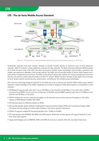
- LTE is becoming the de facto standard for 4G mobile networks due to its high data rates and ability to work with existing network infrastructure.
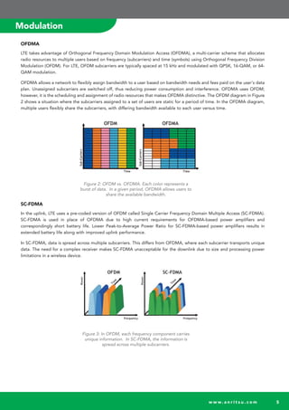
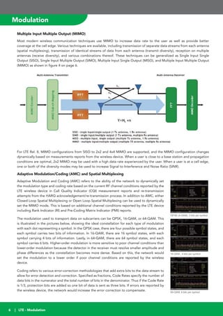
- Key LTE technologies allow for flexible use of spectrum and high throughput including OFDMA, MIMO, and adaptive modulation.
- LTE network components include the UE, eNB, MME, S-GW, and P-GW which work together to route data and control connectivity.
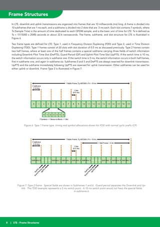
- Frame structures in LTE divide transmissions into 10ms frames for efficient scheduling of resources.
Third revision of IMS signaling course. The lecture was part of the communication protocols class 2014 delivered to students from FIIT STU Bratislava, Slovakia and University Zilina, Slovakia.
For RF Optimisation and neighbour verification both Scanner and UE measurements are required simultaneously
Post-Processing tool is required for data analysis
Individual call failures or drops can be analysed with Drive test tools (e.g. Nemo Outdoor) but to get bigger picture, a proper analysis tool is required
Actix or Nemo Analyser can be used for
Data analysis
Create Maps
Create KPI reports
What LTE Parameters need to be Dimensioned and OptimizedHoracio Guillen
How to Dimension user Traffic in 4G networks
What is the best LTE Configuration
Spectrum analysis for LTE System
MIMO: What is real, What is Wishful thinking
LTE Measurements what they mean and how they are used
How to consider Overhead in LTE Dimensioning and What is the impact
How to take into account customer experience when Designing a Wireless Network
I have described VoLTE IMS Architecture in simplified way . Are you also finding 3GPP Specs complicated & Complex for VoLTE IMS . It covers Role played by individual Networks Elements as mentioned below :-
# VoLTE SIP Handset : SIP Support , UAC , UAS , User Agent , SIP-UA
# Underlying LTE Network : MME , SGW , PGW , PCRF , HSS , Dedicated Bearer , QCI , Default Bearer
# IMS Core : SIP Servers , P-CSCF , I-CSCF , S-CSCF , TAS , MMTEL , BGw , MRF , ATCF , ATGW , IBCF , MGCF , IM-MGW , TrGW
# Voice Core or PSTN Network for Break-in or Break-out Calls
Pequeña presentación sobre las principales partes del teatro griego, para su utilización en el aula con los alumnos de Cultura Clásica y 1ª de Bachillerato.
Radio Link Analysis for 4G TD- LTE Technology at 2.3 GHz FrequencySukhvinder Singh Malik
The Long Term Evolution (LTE) is the latest step in an advancing series of mobile telecommunications systems.
In this paper, authors show interest on the link budgeting the information presented here will help readers understand how the budgeting will be done in LTE. This paper provides
dimensioning of LTE for particular city.
This will provides the number of cell count. Here we tell about a GUI MATLAB System for calculation of no. of resources required to provide services in particular area with optimum cost and better quality.
In a LTE Advanced network there are two main entities involved in communication which are Subscriber Station (SS) and a BS. A BS is typically a service provider which has backhaul connectivity and SS subscribes to the BS for the service. A BS exchange control messages and negotiate the connection parameters with SS before setting up the communication link with it. These parameters may vary during the communication depending on the requirements and availability of resources between the two entities. When a BS try to create link with a SS and if the SS is within the range then BS communicate directly with SS. Otherwise, if SS station is out of the range of the BS or there is coverage limitations or no LOS (line of sight) between the BS and SS then RS is a cost effective solution to overcome this problem. There are two approaches applied in the research towards improving the LTE Advanced network performance. Firstly the placement method should need to be determined in order to cut down the cost as well as maintain the QoS standard. The second scenario is based on the performance evaluation of WiMAX2 network using relay station with in depth analysis of how to increase throughput and reduce delay parameters to improve overall network performance. The QoS class’s comparison also will be included for network flow and its resource usage. In the course of research, various issues have been addressed by providing solutions based on selection of RS and using different modes of RS. LTE Advanced nodes are incorporated to produce useful functionalities; ThesisScientist.com
Simulation and Performance Analysis of Long Term Evolution (LTE) Cellular Net...ijsrd.com
In the development, standardization and implementation of LTE Networks based on Orthogonal Freq. Division Multiple Access (OFDMA), simulations are necessary to test as well as optimize algorithms and procedures before real time establishment. This can be done by both Physical Layer (Link-Level) and Network (System-Level) context. This paper proposes Network Simulator 3 (NS-3) which is capable of evaluating the performance of the Downlink Shared Channel of LTE networks and comparing it with available MatLab based LTE System Level Simulator performance.
PHP Frameworks: I want to break free (IPC Berlin 2024)Ralf Eggert
In this presentation, we examine the challenges and limitations of relying too heavily on PHP frameworks in web development. We discuss the history of PHP and its frameworks to understand how this dependence has evolved. The focus will be on providing concrete tips and strategies to reduce reliance on these frameworks, based on real-world examples and practical considerations. The goal is to equip developers with the skills and knowledge to create more flexible and future-proof web applications. We'll explore the importance of maintaining autonomy in a rapidly changing tech landscape and how to make informed decisions in PHP development.
This talk is aimed at encouraging a more independent approach to using PHP frameworks, moving towards a more flexible and future-proof approach to PHP development.
Essentials of Automations: The Art of Triggers and Actions in FMESafe Software
In this second installment of our Essentials of Automations webinar series, we’ll explore the landscape of triggers and actions, guiding you through the nuances of authoring and adapting workspaces for seamless automations. Gain an understanding of the full spectrum of triggers and actions available in FME, empowering you to enhance your workspaces for efficient automation.
We’ll kick things off by showcasing the most commonly used event-based triggers, introducing you to various automation workflows like manual triggers, schedules, directory watchers, and more. Plus, see how these elements play out in real scenarios.
Whether you’re tweaking your current setup or building from the ground up, this session will arm you with the tools and insights needed to transform your FME usage into a powerhouse of productivity. Join us to discover effective strategies that simplify complex processes, enhancing your productivity and transforming your data management practices with FME. Let’s turn complexity into clarity and make your workspaces work wonders!
Accelerate your Kubernetes clusters with Varnish CachingThijs Feryn
A presentation about the usage and availability of Varnish on Kubernetes. This talk explores the capabilities of Varnish caching and shows how to use the Varnish Helm chart to deploy it to Kubernetes.
This presentation was delivered at K8SUG Singapore. See https://feryn.eu/presentations/accelerate-your-kubernetes-clusters-with-varnish-caching-k8sug-singapore-28-2024 for more details.
GDG Cloud Southlake #33: Boule & Rebala: Effective AppSec in SDLC using Deplo...James Anderson
Effective Application Security in Software Delivery lifecycle using Deployment Firewall and DBOM
The modern software delivery process (or the CI/CD process) includes many tools, distributed teams, open-source code, and cloud platforms. Constant focus on speed to release software to market, along with the traditional slow and manual security checks has caused gaps in continuous security as an important piece in the software supply chain. Today organizations feel more susceptible to external and internal cyber threats due to the vast attack surface in their applications supply chain and the lack of end-to-end governance and risk management.
The software team must secure its software delivery process to avoid vulnerability and security breaches. This needs to be achieved with existing tool chains and without extensive rework of the delivery processes. This talk will present strategies and techniques for providing visibility into the true risk of the existing vulnerabilities, preventing the introduction of security issues in the software, resolving vulnerabilities in production environments quickly, and capturing the deployment bill of materials (DBOM).
Speakers:
Bob Boule
Robert Boule is a technology enthusiast with PASSION for technology and making things work along with a knack for helping others understand how things work. He comes with around 20 years of solution engineering experience in application security, software continuous delivery, and SaaS platforms. He is known for his dynamic presentations in CI/CD and application security integrated in software delivery lifecycle.
Gopinath Rebala
Gopinath Rebala is the CTO of OpsMx, where he has overall responsibility for the machine learning and data processing architectures for Secure Software Delivery. Gopi also has a strong connection with our customers, leading design and architecture for strategic implementations. Gopi is a frequent speaker and well-known leader in continuous delivery and integrating security into software delivery.
DevOps and Testing slides at DASA ConnectKari Kakkonen
My and Rik Marselis slides at 30.5.2024 DASA Connect conference. We discuss about what is testing, then what is agile testing and finally what is Testing in DevOps. Finally we had lovely workshop with the participants trying to find out different ways to think about quality and testing in different parts of the DevOps infinity loop.
In his public lecture, Christian Timmerer provides insights into the fascinating history of video streaming, starting from its humble beginnings before YouTube to the groundbreaking technologies that now dominate platforms like Netflix and ORF ON. Timmerer also presents provocative contributions of his own that have significantly influenced the industry. He concludes by looking at future challenges and invites the audience to join in a discussion.
Alt. GDG Cloud Southlake #33: Boule & Rebala: Effective AppSec in SDLC using ...James Anderson
Effective Application Security in Software Delivery lifecycle using Deployment Firewall and DBOM
The modern software delivery process (or the CI/CD process) includes many tools, distributed teams, open-source code, and cloud platforms. Constant focus on speed to release software to market, along with the traditional slow and manual security checks has caused gaps in continuous security as an important piece in the software supply chain. Today organizations feel more susceptible to external and internal cyber threats due to the vast attack surface in their applications supply chain and the lack of end-to-end governance and risk management.
The software team must secure its software delivery process to avoid vulnerability and security breaches. This needs to be achieved with existing tool chains and without extensive rework of the delivery processes. This talk will present strategies and techniques for providing visibility into the true risk of the existing vulnerabilities, preventing the introduction of security issues in the software, resolving vulnerabilities in production environments quickly, and capturing the deployment bill of materials (DBOM).
Speakers:
Bob Boule
Robert Boule is a technology enthusiast with PASSION for technology and making things work along with a knack for helping others understand how things work. He comes with around 20 years of solution engineering experience in application security, software continuous delivery, and SaaS platforms. He is known for his dynamic presentations in CI/CD and application security integrated in software delivery lifecycle.
Gopinath Rebala
Gopinath Rebala is the CTO of OpsMx, where he has overall responsibility for the machine learning and data processing architectures for Secure Software Delivery. Gopi also has a strong connection with our customers, leading design and architecture for strategic implementations. Gopi is a frequent speaker and well-known leader in continuous delivery and integrating security into software delivery.
Why You Should Replace Windows 11 with Nitrux Linux 3.5.0 for enhanced perfor...SOFTTECHHUB
The choice of an operating system plays a pivotal role in shaping our computing experience. For decades, Microsoft's Windows has dominated the market, offering a familiar and widely adopted platform for personal and professional use. However, as technological advancements continue to push the boundaries of innovation, alternative operating systems have emerged, challenging the status quo and offering users a fresh perspective on computing.
One such alternative that has garnered significant attention and acclaim is Nitrux Linux 3.5.0, a sleek, powerful, and user-friendly Linux distribution that promises to redefine the way we interact with our devices. With its focus on performance, security, and customization, Nitrux Linux presents a compelling case for those seeking to break free from the constraints of proprietary software and embrace the freedom and flexibility of open-source computing.
Transcript: Selling digital books in 2024: Insights from industry leaders - T...BookNet Canada
The publishing industry has been selling digital audiobooks and ebooks for over a decade and has found its groove. What’s changed? What has stayed the same? Where do we go from here? Join a group of leading sales peers from across the industry for a conversation about the lessons learned since the popularization of digital books, best practices, digital book supply chain management, and more.
Link to video recording: https://bnctechforum.ca/sessions/selling-digital-books-in-2024-insights-from-industry-leaders/
Presented by BookNet Canada on May 28, 2024, with support from the Department of Canadian Heritage.
Elevating Tactical DDD Patterns Through Object CalisthenicsDorra BARTAGUIZ
After immersing yourself in the blue book and its red counterpart, attending DDD-focused conferences, and applying tactical patterns, you're left with a crucial question: How do I ensure my design is effective? Tactical patterns within Domain-Driven Design (DDD) serve as guiding principles for creating clear and manageable domain models. However, achieving success with these patterns requires additional guidance. Interestingly, we've observed that a set of constraints initially designed for training purposes remarkably aligns with effective pattern implementation, offering a more ‘mechanical’ approach. Let's explore together how Object Calisthenics can elevate the design of your tactical DDD patterns, offering concrete help for those venturing into DDD for the first time!
The Art of the Pitch: WordPress Relationships and SalesLaura Byrne
Clients don’t know what they don’t know. What web solutions are right for them? How does WordPress come into the picture? How do you make sure you understand scope and timeline? What do you do if sometime changes?
All these questions and more will be explored as we talk about matching clients’ needs with what your agency offers without pulling teeth or pulling your hair out. Practical tips, and strategies for successful relationship building that leads to closing the deal.
UiPath Test Automation using UiPath Test Suite series, part 4DianaGray10
Welcome to UiPath Test Automation using UiPath Test Suite series part 4. In this session, we will cover Test Manager overview along with SAP heatmap.
The UiPath Test Manager overview with SAP heatmap webinar offers a concise yet comprehensive exploration of the role of a Test Manager within SAP environments, coupled with the utilization of heatmaps for effective testing strategies.
Participants will gain insights into the responsibilities, challenges, and best practices associated with test management in SAP projects. Additionally, the webinar delves into the significance of heatmaps as a visual aid for identifying testing priorities, areas of risk, and resource allocation within SAP landscapes. Through this session, attendees can expect to enhance their understanding of test management principles while learning practical approaches to optimize testing processes in SAP environments using heatmap visualization techniques
What will you get from this session?
1. Insights into SAP testing best practices
2. Heatmap utilization for testing
3. Optimization of testing processes
4. Demo
Topics covered:
Execution from the test manager
Orchestrator execution result
Defect reporting
SAP heatmap example with demo
Speaker:
Deepak Rai, Automation Practice Lead, Boundaryless Group and UiPath MVP
Removing Uninteresting Bytes in Software FuzzingAftab Hussain
Imagine a world where software fuzzing, the process of mutating bytes in test seeds to uncover hidden and erroneous program behaviors, becomes faster and more effective. A lot depends on the initial seeds, which can significantly dictate the trajectory of a fuzzing campaign, particularly in terms of how long it takes to uncover interesting behaviour in your code. We introduce DIAR, a technique designed to speedup fuzzing campaigns by pinpointing and eliminating those uninteresting bytes in the seeds. Picture this: instead of wasting valuable resources on meaningless mutations in large, bloated seeds, DIAR removes the unnecessary bytes, streamlining the entire process.
In this work, we equipped AFL, a popular fuzzer, with DIAR and examined two critical Linux libraries -- Libxml's xmllint, a tool for parsing xml documents, and Binutil's readelf, an essential debugging and security analysis command-line tool used to display detailed information about ELF (Executable and Linkable Format). Our preliminary results show that AFL+DIAR does not only discover new paths more quickly but also achieves higher coverage overall. This work thus showcases how starting with lean and optimized seeds can lead to faster, more comprehensive fuzzing campaigns -- and DIAR helps you find such seeds.
- These are slides of the talk given at IEEE International Conference on Software Testing Verification and Validation Workshop, ICSTW 2022.
Securing your Kubernetes cluster_ a step-by-step guide to success !KatiaHIMEUR1
Today, after several years of existence, an extremely active community and an ultra-dynamic ecosystem, Kubernetes has established itself as the de facto standard in container orchestration. Thanks to a wide range of managed services, it has never been so easy to set up a ready-to-use Kubernetes cluster.
However, this ease of use means that the subject of security in Kubernetes is often left for later, or even neglected. This exposes companies to significant risks.
In this talk, I'll show you step-by-step how to secure your Kubernetes cluster for greater peace of mind and reliability.
Climate Impact of Software Testing at Nordic Testing DaysKari Kakkonen
My slides at Nordic Testing Days 6.6.2024
Climate impact / sustainability of software testing discussed on the talk. ICT and testing must carry their part of global responsibility to help with the climat warming. We can minimize the carbon footprint but we can also have a carbon handprint, a positive impact on the climate. Quality characteristics can be added with sustainability, and then measured continuously. Test environments can be used less, and in smaller scale and on demand. Test techniques can be used in optimizing or minimizing number of tests. Test automation can be used to speed up testing.
2. 2
Introduction
Table of Contents
Abstract.....................................................................................................................................................
References.................................................................................................................................................
LTE - The de facto Mobile Access Standard.................................................................................................................
OFDMA.....................................................................................................................................................
SC-FDMA...................................................................................................................................................
Multiple Input Multiple Output (MIMO) Adaptive Modulation and Coding (AMC).....................................................
LTE Network Components and Functions....................................................................................................................
Frame Structures..........................................................................................................................................................
LTE Frame Structure and Bandwidth Concepts...........................................................................................................
LTE Downlink Channels and Signals.............................................................................................................................
LTE Uplink Channels and Signals..................................................................................................................................
LTE Bands, Channel Bandwidths, and Frequency Allocations.............................................................................
Radio Protocol Architecture........................................................................................................................................
RRC States and Inter-RAT Mobility (3GPP)...................................................................................................................
RRC Messages.............................................................................................................................................................
Paging..........................................................................................................................................................................
RRC Connection Establishment...................................................................................................................................
Security.........................................................................................................................................................................
MD8430A Signaling Tester: LTE Base Station Emulator.............................................................................................
Conformance Test........................................................................................................................................................
Testers, Analyzers and Generators..............................................................................................................................
Handheld Test.............................................................................................................................................................
LTE IQproducer............................................................................................................................................................
3
3
4
5
5
6
7
8
9
10
11
12
13
14
14
16
16
17
18
19
20
21
23
| LTE - Contents
3. 3w w w. a n r i t s u . c o m
Mobile/Wireless
Abstract
Many global wireless carriers have announced plans to deploy Long Term Evolution (LTE) technology, with 3 operators
already providing commercial service as of this writing, and many more launches planned through 2010 and beyond. The
primary reason for the transition from 3G technology to LTE is the benefits that this technology provides to both the
consumer and carrier, including both increased bandwidth and lower network latency to the consumer as well as lower
cost per data bit to the carrier.
Incumbent with any new generation technology is a host of technical challenges, so these areas must be tested and
optimized before deployment. For LTE, a few of these challenges include optimizing and maximizing data rates under a
variety of conditions, ensuring seamless handovers to current 2G and 3G networks, and verifying that the devices roam to
the correct network when outside “home” conditions. Only after these and other parameters are tested and optimized
can quality of the LTE devices and network equipment be assured.
Anritsu is proud to offer a complete line of LTE test solutions to ensure the performance and quality of LTE devices and
network equipment. For LTE device-focused testing, the MD8430A LTE Signaling Tester is the first complete LTE network
simulator, with capability to simulate up to 6 cells on 4 RF channels (including 2x2 and 4x2 MIMO), and optional fading
using the MF6900A Baseband Fading Simulator. A variety of user interfaces are available for this instrument, including C-
scenarios, Testing and Test Control Notation (TTCN), and the unique device Rapid Test Designer graphical environment.
The MD8430A is used as a building block in turnkey LTE test systems including the ME7832L LTE Protocol Conformance
Test System, the ME7873L RF Conformance Test System, and various operator-focused test solutions. As an alternative to
full RF conformance testing, the MT8820C One-Box Tester is also available for LTE and 2G/3G testing, and is optimized
for a variety of applications from R&D to pre-conformance to manufacturing.
Anritsu also offers flexible test solutions which can be used for testing of either LTE devices or enhanced Node Bs (eNBs).
The MS269xA and MS2830A Vector Signal Analyzers provide both LTE uplink and downlink analysis as well as optional
signal generation, while the MG3700A Vector Signal Generator produces realistic LTE signals with available MIMO
configurations. For signal generation in any of these platforms, the PC-based LTE IQProducer software provides a
graphical interface, enabling the user to quickly and easily generate LTE-compliant waveforms, with options for either FDD
or TDD variants. For field and other portable applications, Anritsu also offers LTE analysis using the BTS Master, Cell
Master, and Spectrum Master series of products, with available vector signal generator capability in the MT8221B BTS
Master.
This LTE Resource Guide provides in-depth knowledge of LTE and Next Generation Networks and serves as an excellent
educational and reference tool on the technology. Areas covered include modulation formats, network components, frame
structures, and physical channels and signals.
References
All 3rd Generation Partnership Project (3GPP) TS 36 series standards are available at http://www.3gpp.org/ftp/Specs/html-
info/36-series.htm.
• 3GPP TS 36.101: User Equipment (WIRELESS DEVICE) Radio Transmission and Reception
• 3GPP TS 36.104: Base Station (BS) Radio Transmission and Reception
• 3GPP TS 36.141: BS Conformance Testing
• 3GPP TS 36.201: Physical Layer - General Description
• 3GPP TS 36.211: Physical Channels and Modulation
• 3GPP TS 36.212: Multiplexing and Channel Coding
• 3GPP TS 36.213: Physical Layer Procedures
• 3GPP TS 36.214: Physical Layer - Measurements
• 3GPP TS 36.300: Overall description
• 3GPP TS 36.508: Common Test Environments for UE Conformance Testing
• 3GPP TS 36.521-1: UE Conformance Specification; Radio Transmission and Reception; Part 1: Conformance Testing
• 3GPP TS 36.521-3: UE Conformance Specification; Radio Transmission and Reception; Part 3: Radio Resource
Management (RRM) Conformance Testing
• 3GPP TS 36.521-3: UE Conformance Specification; Part 1: Protocol Conformance Specification
4. 4
LTE
| LTE - The de facto mobile access standard
Traditionally, operators have built multiple networks to provide multiple services to customers such as fixed telephone
networks, cable TV networks, cellular telephone networks and data networks. The Next Generation Network (NGN) provides
all of these functions using a flat all-IP core that interconnects multiple access technologies and provides a consistent and
reliable user-experience regardless of the access method. The NGN core will provide Quality of Service (QoS) support and a
wide variety of applications and services. The NGN access network will provide mobility and routing management and ensure
that the core sees the mobile networks simply as another IP network. Mobile handover between access types will be seamless
as the IP access network controls security, authentication, and billing for the multiple access technologies.
LTE is the first technology designed explicitly for the NGN and is set to become the de-facto NGN mobile access network
standard. It takes advantage of the NGN's capabilities to provide an always-on mobile data experience comparable to wired
networks.
• LTE Release 8 supports peak data rates of up to 326 Mbps on the downlink and 86 Mbps on the uplink with a 20 MHz
channel and 4x4 MIMO. A more common configuration of 20 MHz and 2x2 MIMO supports peak rates of 173 Mbps on the
downlink and 58 Mbps on the uplink.
• LTE Rel. 8 allows for over four times the throughput on the downlink and over five times the throughput on the uplink
relative to HSPA Release 8 (HSPA+/DC-HSPA).
• LTE improves spectrum efficiency relative to HSPA+.
• LTE provides flexible duplex methods including both Frequency Division Duplex (FDD) and Time Division Duplex (TDD).
This allows LTE technology to fit within either existing or new carrier spectrum allocations.
• LTE Rel. 8 supports scalable RF channel bandwidths from 1.4 MHz to 20 MHz.
• LTE interoperates with CDMA2K, W-CDMA and GSM systems. Multimode wireless devices will support handover to and
from these other systems.
• Legacy technologies such as CDMA2K, HSPA and GSM will continue to operate within the new data infrastructure.
LTE - The de facto Mobile Access Standard
Figure 1: LTE supports the Next generation Network by providing mobile access to an all-IP core.
5. 5w w w. a n r i t s u . c o m
OFDMA
LTE takes advantage of Orthogonal Frequency Domain Modulation Access (OFDMA), a multi-carrier scheme that allocates
radio resources to multiple users based on frequency (subcarriers) and time (symbols) using Orthogonal Frequency Division
Modulation (OFDM). For LTE, OFDM subcarriers are typically spaced at 15 kHz and modulated with QPSK, 16-QAM, or 64-
QAM modulation.
OFDMA allows a network to flexibly assign bandwidth to a user based on bandwidth needs and fees paid on the user's data
plan. Unassigned subcarriers are switched off, thus reducing power consumption and interference. OFDMA uses OFDM;
however, it is the scheduling and assignment of radio resources that makes OFDMA distinctive. The OFDM diagram in Figure
2 shows a situation where the subcarriers assigned to a set of users are static for a period of time. In the OFDMA diagram,
multiple users flexibly share the subcarriers, with differing bandwidth available to each user versus time.
SC-FDMA
In the uplink, LTE uses a pre-coded version of OFDM called Single Carrier Frequency Domain Multiple Access (SC-FDMA).
SC-FDMA is used in place of OFDMA due to high current requirements for OFDMA-based power amplifiers and
correspondingly short battery life. Lower Peak-to-Average Power Ratio for SC-FDMA-based power amplifiers results in
extended battery life along with improved uplink performance.
In SC-FDMA, data is spread across multiple subcarriers. This differs from OFDMA, where each subcarrier transports unique
data. The need for a complex receiver makes SC-FDMA unacceptable for the downlink due to size and processing power
limitations in a wireless device.
Figure 2: OFDM vs. OFDMA. Each color represents a
burst of data. In a given period, OFDMA allows users to
share the available bandwidth.
Figure 3: In OFDM, each frequency component carries
unique information. In SC-FDMA, the information is
spread across multiple subcarriers.
Modulation
6. 6
Modulation
| LTE - Modulation
Multiple Input Multiple Output (MIMO)
Most modern wireless communication techniques use MIMO to increase data rate to the user as well as provide better
coverage at the cell edge. Various techniques are available, including transmission of separate data streams from each antenna
(spatial multiplexing), transmission of identical streams of data from each antenna (transmit diversity), reception on multiple
antennas (receive diversity), and various combinations thereof. These techniques can be generalized as Single Input Single
Output (SISO), Single Input Multiple Output (SIMO), Multiple Input Single Output (MISO), and Multiple Input Multiple Output
(MIMO) as shown in figure 4 on page 6.
For LTE Rel. 8, MIMO configurations from SISO to 2x2 and 4x4 MIMO are supported, and the MIMO configuration changes
dynamically based on measurements reports from the wireless device. When a user is close to a base station and propagation
conditions are optimal, 2x2 MIMO may be used with a high data rate experienced by the user. When a user is at a cell edge,
one or both of the diversity modes may be used to increase Signal to Interference and Noise Ratio (SINR).
Adaptive Modulation/Coding (AMC) and Spatial Multiplexing
Adaptive Modulation and Coding (AMC) refers to the ability of the network to dynamically set
the modulation type and coding rate based on the current RF channel conditions reported by the
LTE wireless device in Call Quality Indicator (CQI) measurement reports and re-transmission
attempts from the HARQ acknowledgement/re-transmission process. In addition to AMC, either
Closed Loop Spatial Multiplexing or Open Loop Spatial Multiplexing can be used to dynamically
set the MIMO mode. This is based on additional channel conditions reported by the LTE device
including Rank Indicator (RI) and Pre-Coding Matrix Indicator (PMI) reports.
The modulation used to transport data on subcarriers can be QPSK, 16-QAM, or 64-QAM. This
is illustrated in the pictures below, showing the ideal constellation for each type of modulation
with each dot representing a symbol. In the QPSK case, there are four possible symbol states, and
each symbol carries two bits of information. In 16-QAM, there are 16 symbol states, with each
symbol carrying 4 bits of information. Lastly, in 64-QAM, there are 64 symbol states, and each
symbol carries 6 bits. Higher-order modulation is more sensitive to poor channel conditions than
lower-order modulation because the detector in the receiver must resolve smaller amplitude and
phase differences as the constellation becomes more dense. Based on this, the network would
set the modulation to a lower order if poor channel conditions are reported by the wireless
device.
Coding refers to various error-correction methodologies that add extra bits to the data stream to
allow for error detection and correction. Specified as fractions, Code Rates specify the number of
data bits in the numerator and the total number of bits in the denominator. Thus if the Code Rate
is 1/3, protection bits are added so one bit of data is sent as three bits. If errors are reported by
the wireless device, the network would increase the error correction to compensate.
7. w w w. a n r i t s u . c o m
LTE Network Components
| LTE Network Components
UE (User Equipment)
• Access device for user.
• Provides measurements that indicate channel conditions
to the network.
eNB (Enhanced Node B)
• Hosts the PHYsical (PHY), Medium Access Control (MAC),
Radio Link Control (RLC), and Packet Data Convergence
Protocol (PDCP) layers.
• Controls user-plane header-compression and encryption.
• Provides Radio Resource Control (RRC) functionality for
the control plane.
• Functions include radio resource management, admission
control, scheduling, enforcement of negotiated uplink
QoS, cell information broadcast, ciphering/deciphering of
user and control plane data, and compression and
decompression of downlink and uplink user-plane packet
headers.
PDN Gateway (P-GW)
• Provides connectivity between the UE and external packet
data networks (PDNs) by being the point of exit and entry
for UE traffic (A UE may have simultaneous connectivity
with more than one P-GW for accessing multiple PDNs).
• Performs policy enforcement, packet filtering for each
user, charging support, lawful Interception, and packet
screening.
• Acts as the anchor for mobility between 3GPP and non-
3GPP technologies such as WiMAX and 3GPP2 (CDMA 1X
and EvDO).
MME (Mobility Management Entity)
• Acts as the key control node for the LTE network.
• Responsible for idle mode UE tracking and paging
procedure including retransmissions.
• Controls bearer activation/deactivation process.
• Chooses the Serving Gateway (S-GW) for a UE at initial
attachment and at the time of intra-LTE handover.
• Authenticates the user by interacting with the Home
Subscriber Server (HSS) [Not shown in diagram].
• Serves as the termination point for the Non-Access
Stratum (NAS) signaling. NAS signaling is responsible for
generation and allocation of temporary identities to UEs
and checks the authorization of the UE to camp on the
system.
• Serves as the termination point for ciphering and integrity
protection for NAS signaling.
• Handles security key management.
• Provides control plane function for mobility between LTE
and other access networks.
Serving Gateway (S-GW)
• Routes and forwards user data packets.
• Acts as the mobility anchor for the user plane during inter-
eNB handovers and as the anchor for mobility between
LTE and other 3GPP technologies.
• Terminates the downlink data path for idle state UEs and
triggers paging when DL data arrives for the UE.
• Manages and stores UE contexts, e.g. parameters of the
IP bearer service and network internal routing information.
LTE Network Components and Functions
Figure 5: TRadio Acccess Network S1 is the physical interface between the eNB and the MME.
7w w w. a n r i t s u . c o m
8. Frame Structures
In LTE, downlink and uplink transmissions are organized into frames that are 10 milliseconds (ms) long. A frame is divided into
10 subframes that are 1 ms each, and a subframe is divided into 2 slots that are .5 ms each. Each slot contains 7 symbols, where
Ts (Sample Time) is the amount of time dedicated to each OFDM sample, and is the basic unit of time for LTE. Ts is defined as
Ts = 1/(15000 x 2048) seconds or about 32.6 nanoseconds. The frame, subframe, and slot structure for LTE is illustrated in
Figure 6.
Two frame types are defined for LTE: Type 1, used in Frequency Division Duplexing (FDD) and Type 2, used in Time Division
Duplexing (TDD). Type 1 frames consist of 20 slots with slot duration of 0.5 ms as discussed previously. Type 2 frames contain
two half frames, where at least one of the half frames contains a special subframe carrying three fields of switch information
including Downlink Pilot Time Slot (DwPTS), Guard Period (GP) and Uplink Pilot Time Slot (UpPTS). If the switch time is 10 ms,
the switch information occurs only in subframe one. If the switch time is 5 ms, the switch information occurs in both half frames,
first in subframe one, and again in subframe six. Subframes 0 and 5 and DwPTS are always reserved for downlink transmission.
UpPTS and the subframe immediately following UpPTS are reserved for uplink transmission. Other subframes can be used for
either uplink or downlink. Frame Type 2 is illustrated in Figure 7.
Figure 6: Type 1 frame type, timing and symbol allocations shown for FDD with normal cyclic prefix (CP)
Figure 7: Type 2 frame. Special fields are shown in Subframes 1 and 6. Guard period separates the Downlink and Up-
link. This TDD example represents a 5 ms switch point. A 10 ms switch point would not have the special fields
in subframe 6.
| RF and Microwave Testing Solutions8 | LTE - Frame Structures
Frame Structures
9. Frame Structures
LTE Frame Structures and Bandwidth Concepts
As explained previously, in LTE, 10 one ms subframes
comprise a 10 ms frame, two 0.5 ms slots comprise a one
ms subframe, and 7 symbols comprise a .5 ms slot. Moving
from this time-domain viewpoint to one taking into
account both time and frequency aspects, the smallest
modulation structure in LTE is one symbol in time vs. one
subcarrier in frequency and is called a Resource Element
(RE). Resource Elements are further aggregated into
Resource Blocks (RB), with the typical RB having
dimensions of 7 symbols by 12 subcarriers. The RE and RB
structure is shown in Figure 8.
The number of symbols in a RB depends on the Cyclic
Prefix (CP) in use. When a normal CP is used, the RB
contains seven symbols. When an extended CP is used
due to extreme delay spread or multimedia broadcast
modes, the RB contains six symbols.
Channel bandwidth used by a carrier depends on
spectrum allocation from local regulatory agencies like the
FCC in the US, and is typically purchased through an
auction or other similar means. The spectrum allocated
may be paired spectrum for use with FDD
communications, or unpaired spectrum for use with TDD
communications.
Figure 8: Relationship between a slot, symbols and Resource
Blocks. N is the symbol used to indicate the maximum number
of downlink Resource Blocks for a given bandwidth.
DL
RB
Physically, channel bandwidth is the width of the channel in frequency as measured from the lowest channel edge to the highest
channel edge. In unpaired spectrum, channel bandwidth is simply the width of the channel in frequency. In paired spectrum,
channel bandwidth is the width of the uplink or downlink in frequency (typically the same).
The number of RBs that can fit within a given channel bandwidth varies proportionally to the bandwidth. Logically, as the
channel bandwidth increases, the number of RBs can increase. The Transmission Bandwidth Configuration is the maximum
number of Resource Blocks that can fit within the channel bandwidth with some guard band. Given a channel bandwidth at the
maximum channel bandwidth of 20 MHz for LTE Rel. 8, 100 RBs can fit within this bandwidth. These concepts are shown in
Figure 9.
Figure 9: Relationship between Channel bandwidth, Transmission
Bandwidth Configuration, and Transmission Bandwidth. Figure 10: Transmission Bandwidth Con-
figuration
w w w. a n r i t s u . c o m 9
10. 10 | LTE - Physical Channels & Signals
LTE Downlink Channels and Signals
The LTE frame carries both physical
channels and physical signals, positioned by
the LTE standard at certain positions in the
frame in terms of subcarriers and symbols.
Channels are defined as carrying
information received from higher layers.
Signals are defined as originating at the
physical layer. The next sections will review
the functions of these physical layer
channels and signals as well as their
positioning in the frame structure.
Figure 11: This diagram of a downlink frame using FDD and normal CP shows the relative location of the various physical
channels. Frames in systems using extended CP or TDD would be slightly different.
Download Physical Channels
Physical Downlink Shared Channel (PDSCH)
Used to transport user data, the PDSCH is designed for high data rates. Modulation options include QPSK, 16-QAM, and 64-
QAM. Spatial multiplexing is exclusive to the PDSCH. The Resource Blocks associated with this channel are shared among users
via OFDMA.
Physical Broadcast Channel (PBCH)
The PBCH is used to send cell-specific system identification and access control parameters every 4th frame (40 ms) using QPSK
modulation.
Physical Control Format Indicator Channel (PCFICH)
The PCFICH is used to inform the wireless device how many OFDM symbols will be used for the PDCCH in a subframe, ranging
from 1 to 3. The PCFICH uses QPSK modulation.
Physical Downlink Control Channel (PDCCH)
Wireless devices obtain uplink and downlink resource scheduling allocations from the PDCCH. The PDCCH maps onto resource
elements in up to the first three OFDM symbols in the first slot of a subframe and uses QPSK modulation. The value of the
PCFICH indicates the number of symbols used for the PDCCH (not shown in diagram).
Physical Multicast Channel (PMCH)
The PMCH carries multimedia broadcast information, and like the PDSCH, the PMCH has multiple options for modulation
including QPSK, 16-QAM, or 64-QAM. Multicast information can be sent to multiple wireless devices simultaneously (not shown
in diagram)..
Physical Hybrid ARQ Indicator Channel (PHICH)
PHICH carries ACK/NACKs in response to uplink transmissions in order to request retransmission or confirms the receipt of
blocks of data. ACKs and NACKs are part of the HARQ mechanism (not shown in diagram).
Physical Channels & Signals
11. w w w. a n r i t s u . c o m
LTE Downlink Channels and Signals
Reference Signal (RS)
Wireless devices use the RS for downlink channel estimation. They allow the wireless device to determine the channel impulse
response (CIR). RS’s are the product of a two-dimensional orthogonal sequence and a two-dimensional pseudo-random se-
quence. Since there are 3 different sequences available for the orthogonal sequence and 170 possible sequences for the
pseudorandom number (PRN), the specification identifies 510 RS sequences. The RS uses the first and fifth symbols under nor-
mal CP operation, and the first and fourth symbols for extended CP operation; the location of the RS on the subcarriers
varies.
Primary and Secondary Synchronization Signal (P-SS and S-SS)
Wireless devices use the Primary Synchronization Signal (P-SS) for timing and frequency acquisition during cell search. The P-
SS carries part of the cell ID and provides slot timing synchronization. It is transmitted on 62 of the reserved 72 subcarriers (6
Resource Blocks) around DC on symbol 6 in slot 0 and 10 and uses one of three Zadoff-Chu sequences. Wireless devices use
the Secondary Synchronization Signal (S-SS) in cell search. It provides frame timing synchronization and the remainder of the
cell ID, and is transmitted on 62 of the reserved 72 subcarriers (6 Resource Blocks) around DC on symbol 5 in slot 0 and 10.
The S-SS uses two 31-bit binary sequences and BPSK modulation.
LTE Uplink Channels and Signals
Uplink Physical Channels
Physical Uplink Control Channel (PUCCH)
The PUCCH carries uplink control information and is never transmitted
simultaneously with PUSCH data. PUCCH conveys control information
including channel quality indication (CQI), ACK/NACK responses of the
UE to the HARQ mechanism, and uplink scheduling requests.
Physical Uplink Shared Channel (PUSCH)
Uplink user data is carried by the PUSCH. Resources for the PUSCH are allocated on a sub-frame basis by the UL scheduler.
Subcarriers are allocated in units of RB’s, and may be hopped from sub-frame to sub-frame. The PUSCH may employ QPSK,
16-QAM, or 64-QAM modulation.
Physical Random Access Channel (PRACH)
The PRACH carries the random access preamble and coordinates and transports random requests for service from UE’s. The
PRACH channel transmits access requests (bursts) when a wireless device desires to access the LTE network (call origination or
paging response).
Uplink Physical Signals
Uplink Reference Signal
There are two variants of the UL reference signal. The demodulation reference signal facilitates coherent demodulation, and is
transmitted in the fourth SC-FDMA symbol of the slot. A sounding reference signal is also used to facilitate frequency-
dependent scheduling. Both variants of the UL reference signal use Constant Amplitude Zero Autocorrelation (CAZAC)
sequences.
Downlink Physical Channels
Figure 12: LTE Uplink Subframe with Normal
Cyclic Prefix
w w w. a n r i t s u . c o m 11
12. 12 | LTE Bands
LTE Bands, Channel bandwidths and frequency allocations
LTE Operating Bands indicates the carrier frequency to be used. Not all LTE frequency bands support all bandwidths. The chart
includes both FDD and TDD bands.
Figure 13: Bands and channel bandwidths
LTE Bands
13. w w w. a n r i t s u . c o m
Radio Protocol Architecture
NAS Security
Idle State Mobility
Handling
MME
NAS
RRC
UE
PDCP
RLCRLC
PHY
MAC
Inter Cell RRM
RB Control
UE
Connection Mobility Ctrl
Radio Admission Ctrl
Dynamic Resource
Allocation (Scheduler)
eNB Measurement
Config. & Provision
RRC
PDCP
RLC
MAC
PHY
EPS Bearer Control
Mobility
Anchoring
S-GW
UE IP Address
allocation
P-GW
Packet Filtering
E-UTRAN Evolved Packet Core (EPC)
Air
Interface
S1
AS
Control Plane Protocol
Radio Protocol Architecture: L3 Control Plane
RRC Main Functions
• Broadcast of system information, including NAS common information.
• RRC connection control:
• Paging
• Establishment/ modification/ release of RRC connection (SRBs) and DRBs
• Initial security activation (integrity protection (CP) and AS ciphering (CP, UP))
• RRC connection mobility including e.g. intra-frequency and inter-frequency handover, associated security handling
• Radio configuration control including e.g. assignment/ modification of ARQ configuration, HARQ configuration,
DRX configuration
• QoS control including assignment/modification of semi-persistent configuration information for DL and UL,
assignment/modification of parameters for UL rate control in the UE
• Recovery from radio link failure
• Inter-RAT mobility including e.g: security activation, transfer of RRC context information
• Measurement configuration control and reporting:
• Establishment/ modification/ release of measurements
• Configuration and (de-)activation of measurement gaps
• Measurement reporting
w w w. a n r i t s u . c o m 13
14. • RRCConnectionReconfiguration
• RRCConnectionReconfigurationComplete
• RRCConnectionReestablishment
• RRCConnectionReestablishmentComplete
• RRCConnectionReestablishmentReject
• RRCConnectionReestablishmentRequest
• RRCConnectionReject
• RRCConnectionRelease
• RRCConnectionRequest
• RRCConnectionSetup
• RRCConnectionSetupComplete
• SecurityModeCommand
• SecurityModeComplete
• SecurityModeFailure
• SystemInformation
• MasterInformationBlock
• SystemInformationBlockType1
• UECapabilityEnquiry
• UECapabilityInformation
• DLInformationTransfer
• ULInformationTransfer
• CounterCheck
• ConuterCheckResponse
• MobilityFromEUTRACommand
• HandoverFromEUTRAPreparationRequest (C2K)
• ULHandoverPreparationTransfer (C2K)
• CSFBParametersRequestCDMA2000
• CSFBParametersResponseCDMA2000
• MeasurementReport
• Paging
RRC Messages
RRC States
CELL_DCH
CELL_FACH
CELL_FACH
URA_PCH
Connection
Establishment/
Release
UTRA_Idle
E-UTRA
RRC CONNECTED
E-UTRA
RRC IDLE
GSM_Connected
GPRS Packet
Transfer Mode
GSM_Idle/GPRS
Packet_Idle
Connection
Establishment/
Release
Connection
Establishment/
Release
Handover
Reselection
Handover
Reselection
CCO, Reselection
CCO,
Reselection
CCO
with NACC
Reselection
RRC States and Inter-RAT Mobility Procedures (3GPP)
Radio Bearer Types
• SRB (Signalling Radio Bearers), used to carry C-Plane traffic, i.e. RRC signalling messages.
• RRC messages can contain other messages, such as NAS messages or HRPD/1xRTT messages.
• There are three SRBs, all MUST be established.
• DRB (Data Radio Bearers), used to carry U-Plane traffic (user data).
• Carry IP packets
Signal Radio Bearers
• SRBs are used only for transmission of RRC or NAS messages
• Three SRBs are defined:
• SRB0 is for RRC messages using the CCCH logical channel.
• SRB1 is for RRC messages (which may include a piggybacked NAS message) as well as for NAS messages prior to
the establishment of SRB2, all using DCCH logical channel.
• SRB2 is for NAS messages, using DCCH logical channel. SRB2 has a lower-priority than SRB1 and is always config
ured by E-UTRAN after security activation.
• All RRC messages are integrity protected and ciphered by PDCP.
• NAS independently applies integrity protection and ciphering to the NAS messages.
| RF and Microwave Testing Solutions
RRC States
14 | LTE - RRC States and Inter-RAT Mobility Procedures (3GPP)
15. System Information
• Transmitted periodically on BCCH.
• MIB contains crucial cell information (e.g. bandwidth) and is transmitted on a fixed schedule, i.e. every 40 ms
• Dynamic scheduling: SIB1 (80 ms periodicity) contains information about scheduling of other SIBs
• SIBs are grouped in SI (System Information) “containers”
• Each SI can contain several SIBs.
• Each SI can have a different schedule (transmission
frequency).
• Each SI has to be sent in a single subframe.
• Only one SI can be sent in a subframe.
• MIB (Master Information Block) transmitted on BCCH
mapped on BCH mapped on PBCH.
• SIBs are transmitted on BCCH mapped on DL-SCH mapped
on PDSCH.
UE E-UTRAN
MasterInformationBlock
SystemInformationBlockType1
SystemInformation
w w w. a n r i t s u . c o m 15
System Information Blocks
• MIB - defines the most essential physical layer information of the cell required to receive further system information .
• SIB1 - contains information relevant when evaluating if a UE is allowed to access a cell and defines the scheduling of other
system information blocks.
• SIB2 - contains common and shared channel information.
• SIB3 - contains cell re-selection information.
• SIB4 - contains information about the serving neighbouring frequencies and intra-frequency neighbouring cells relevant for
cell re-selection, covering both E UTRA and other RATs.
• SIB5 - contains information about other E UTRA frequencies and inter-frequency neighbouring cells relevant for cell re-se-
lection.
• SIB6 - contains information about UTRA frequencies and UTRA neighbouring cells relevant for cell re-selection.
• SIB7 - contains information about GERAN frequencies and GERAN neighbouring cells relevant for cell re-
selection/handover.
• SIB8 - contains information about CDMA2000 frequencies and CDMA2000 neighbouring cells relevant for cell re-selec-
tion/handover.
• SIB9 - contains a home eNB identifier (HNBID)
• SIB10 - contains an ETWS primary notification
• SIB11 - contains an ETWS secondary notification
Change Notification Updated Information
Change Notification BCCH Modulation Period (n + 1)
System information can change every BCCH modification period.
• Notification about system information change:
• Both in RRC_IDLE and RRC_CONNECTED a Paging message containing systemInfoModification is used to inform
the UE about SI change
• If an SI-RNTI is discovered on PDCCH, the UE reads SIB1 at the next modification message boundary
• SIB1 contains a value tag indicating that content of other SIBs (except MIB and SIB1) has changed. No information
is provided regarding which SIB has changed.
16. Paging
• Transmit paging information to a UE in RRC_IDLE.
• Inform UEs in RRC_IDLE and RRC_CONNECTED about a system information change.
• Inform UEs in RRC_IDLE and RRC_CONNECTED about an ETWS primary notification.
UE E-UTRAN
Paging
• eNB transmits an RRC Paging message on DL-SCH (PDSCH) at Paging Occasions
• One Paging Frame (PF) is one Radio Frame, which may contain one or multiple Paging Occasion(s).
• One Paging Occasion (PO) is a subframe where there may be P-RNTI (Paging RNTI) transmitted on PDCCH ad-
dressing the paging message
• PO and PF are calculated by the eNB and UE using the UE’s C-RNTI
• The UE looks for its identifier in the RRC paging message
Connection Control
• The UE and eNB start connection establishment over SRB0, which has default configuration.
• Well known to the UE, so no need to be signalled
• First, RRC connection establishment involves the establishment of SRB1.
• E-UTRAN completes RRC connection establishment prior to completing the establishment of the S1 connection
• Upon receiving the UE context from the EPC, E-UTRAN activates AS security (both ciphering and integrity protection) using
the initial RRC-based security activation procedure.
• Next, E-UTRAN initiates the establishment of SRB2 and of radio bearers carrying user data (DRBs)
• E-UTRAN may do this prior to receiving the confirmation of the initial security activation from the UE
• A Default Bearer is always established
Paging
| RF and Microwave Testing Solutions16 | LTE - Paging and Security
RRC Connection Establishment
• The purpose is only to establish SRB1
• SRB0, used in this procedure, has a default well-known configuration
• Before connection establishment, RRC is in RRC_IDLE state; after successful completion, RRC is in
RRC_CONNECTED state.
UE E-UTRAN
RRCConnectionRequest
RRCConnectionSetup
RRCConnectionSetupComplete
• RRCConnectionRequest is sent in RA procedure message 3
• RRCConnectionSetup is sent in RA procedure message 4. If the
procedure fails, RRCConnectionReject is sent instead.
• Both RRCConnectionRequest and RRCConnectionSetup are sent
on SRB0 (CCCH)
• RRCConnectionSetupComplete is sent on SRB1 (DCCH), estab-
lished as a result of this procedure
• RRC messages used in this procedure are neither integrity pro-
tected not ciphered
• This procedure is executed prior to security establish-
ment
17. w w w. a n r i t s u . c o m 17
Security
• As a result of the RRC security activation procedure, the AS applies three different security keys:
• One for the integrity protection of RRC signalling (KRRCint),
• One for the encryption of RRC signalling (KRRCenc)
• One for the encryption of user data (KUPenc).
• The integrity and ciphering algorithms can only
be changed upon handover.
• The AS keys (both the base-key and the de-
rived-keys) change upon every handover and
connection re-establishment.
USIM / AuC
UE / HSS
UE / MME
UE / eNB
K
CK, IK
KASME
KNAS enc
KNAS int KeNB
NH
KUP enc
KRRC enc
KRRC int
KeNB*
NCC
Key Hierarchy
• UE calculates keys, checks MAC (Message Authentication Code) of SMC and if correct, sends back an integrity
protected and ciphered Security Mode Complete message
• If SMC integrity protection fails (or there is any other activation failure), the UE sends back a SecurityModeFailure
message.
• SRB0 cannot be used after security activation
Ciphering Integrated Protection
NAS Signalling Required and terminated in MME Required and terminated in MME
U-Plane Data Required and terminated in eNB Not required and not supported
RRC Signalling (AS) Required and terminated in eNB Required and terminated in eNB
Security Termination Points
Security Establishment
• The purpose is to configure and activate AS security
• Prerequisites to activating AS security:
• UE must be in RRC_CONNECTED state
• Successful NAS Authentication and Key
Agreement (AKA) procedure – i.e. the UE is
authenticated
• Successful NAS security activation (exchange of NAS SECURITY MODE COMMAND and NAS SECURITY MODE
COMPLETE messages)
UE E-UTRAN
SecurityModeCommand
SecurityModeComplete
• AS security activation must be performed after setting up SRB0 and SRB1 and before setting up SRB2 and any DRBs.
• eNB sends an integrity protected SecurityModeCommand (SMC), containing information on selected algorithms
for AS integrity protection and ciphering
Security
18. | RF and Microwave Testing Solutions18 | LTE - Base Station Emulator
Base Station Emulator
MD8430A Signalling Tester: LTE Base Station Emulator
The MD8430A is the first complete LTE Signaling Tester, allowing for simulation
of multiple eNBs with both 2x2 and 4x2 MIMO, as well as portions of the LTE
network. It allows for protocol-based testing of LTE UEs at RF and higher layers,
and is integrated as a fundamental component of Anritsu's Protocol
Conformance, RF Conformance, and Operator IOT test systems.
Anritsu’s LTE Signaling Tester (MD8430A) allows the user to test any of the LTE
UE layers from PHY to NAS. In addition, applications can be tested under real-
world conditions using an external server. The MD8430A's built-in baseband
capability allows for FPGA-based prototype testing at either sub-speed or real-
time, and helps speed time to market for LTE wireless devices.
The LTE Signaling Tester (MD8430A) can be automated with the user's choice of 3 PC-based user interfaces (UIs) including the
graphical Rapid Test Designer (RTD) software, C-Scenarios, or TTCNbased Protocol Conformance Test (PCT) software. Inter-
RAT handover between technologies is enabled using a system including the MD8480C GSM/W-CDMA Signaling Tester or
MD8470A CDMA2K Signaling Tester as well the appropriate UI software.
Rapid Test Designer (RTD)
The Rapid Test Designer (RTD) software is a revolutionary new tool that speeds the testing of LTE devices by simplifying the
way in which users create, execute, and analyze test cases. Tests are grouped as objects, parameters are set by simply clicking
on the objects, and test cases are easily compiled by linking the objects with lines signifying test flow.
When used with the MD8430A or other available signaling testers, the RTD software provides fast, interactive creation and
execution of tests. The RTD software hides the complexity of testing 3GPP protocols and allows the user to test specific
functions and protocols within the UE without being an expert on all protocol layers. The intuitive graphical interface removes
the need to learn a highly specialized test language like TTCN.
Built upon Anritsu's years of experience in testing 3GPP protocols with the leading wireless device vendors, RTD provides a
broad array of configurable building blocks for designing tests, a catalog of common network settings, interactive error
checking, and an integrated protocol analyzer. Applications include operator acceptance testing, integration testing,
interoperability testing, regression testing, and application testing.
Signal Generat
19. w w w. a n r i t s u . c o m 19
Conformance Test
ME7873L LTE RF Conformance Test System
ME7872L LTE Conformance Test System
The ME7832L LTE Protocol Conformance Test System allows the user to verify
conformance of a UE's protocol stack to 3GPP LTE standards. Pre-written, validated
TTCN3 test cases are available for the system, conforming to GCF Work Items and PTCRB
Request for Tests. The MD8430A used in the ME7832L is highly stable and repeatable. In
addition, the ME7832L offers options for UE automation, allowing the user to conduct
regression tests over extended periods including overnight or over the weekend. The
LTE Protocol Conformance Test System (ME7832L) includes an intelligent test sequencer,
allowing the user to schedule tests using a drag and drop graphical interface, with
automated creation of PICS/PIXIT files. The included protocol analyzer shows complete
sequences including all layers and time stamps, with detailed analysis of any message.
Options are available to allow the user to view, edit, and create custom test cases based
on the 3GPP 36.523 standard.
The ME7873L LTE RF Conformance Test System allows the
user to verify conformance of a UE's RF layer to 3GPP LTE
standards. Prewritten, validated test cases are available for the
system, conforming to GCF Work Items and PTCRB Request
for Tests. The system is extremely flexible, with available
options for any LTE band currently scheduled for deployment,
as well as easily changeable test parameters to enable testing
of UE performance. The LTE RF Conformance Test System
(ME7873L) is a modular system to fit with user requirements,
and can include 36.521-1 tests for Chapter 6 (TX), Chapter 7
(RX), Chapter 8 (Performance), or Chapter 9 (UE Reporting) as
well as 36.521-3 (RRM). A user may compile a test sequence
combining test cases from any of these chapters. Additional
options will be available in the future including inter-RAT
handover tests and TD-LTE.
MF6900A Fading Simulator
The MF6900A Fading Simulator provides a stable, repeatablefaded testing
environment when connected to the MD8430A using a baseband interface. Once
connected, it provides a simple and accurate way to add fading profiles to any test
scenario under either SISO or MIMO conditions.
Digital baseband processing in the Fading Simulator (MF6900A) assures reproducible fading profiles. As there are no analog
or RF circuits, periodic calibration is eliminated, making the MF6900A as easy to maintain as it is to use. In inter-RAT systems
including both the MD8480C GSM/W-CDMA Signaling Tester and the MD8430A LTE Signaling Tester, included fading profiles
allow rapid test setup since the fading profiles are pre-configured and ready to use immediately. The MF6900A is expandable
to accommodate four input ports and four output ports. Software updates add functionality such as 4x2 MIMO.
tor
20. | RF and Microwave Testing Solutions20 | LTE - Testers, Analyzers and Generators
MT8820C LTE One-Box Tester
The MT8820C LTE One-Box Tester is a multi-format 2G, 3G, and LTE tester with capability for
UE calibration, RF parametric testing, and functional testing, including call processing or no-
call based testing. Formats supported include LTE, W-CDMA/HSPA to Release 8, CDMA2K to
1xEV-DO rel. A, TD-SCDMA/HSPA, and GSM/GPRS/E-GPRS. Several high-speed calibration
modes are also included such as Anritsu's “TX/RX Sweep” mode, allowing calibration of TX
and RX in parallel. For current users of either the MT8820B or MT8820A, the MT8820C is a
drop-in replacement with backwards compatibility.
The MT8820C makes testing of LTE physical layer parameters easy and simple, including measurement of both TX and RX
parameters. Parameter setups and pass/fail limits for tests defined in 3GPP 36.521-1 are pre-programmed, including easy setup
of uplink and downlink RB allocations. Options are available for 2x2 MIMO including IP-layer throughput at 100 MB/s downlink
data rates.
MS269xA and MS2830A Vector Signal Analyzers (VSA)
Anritsu's MS269xA and MS2830A-series high performance VSAs perform multi-format signal
analysis, including LTE uplink and downlink analysis with optional signal generation. The
MS269xA is focused on applications requiring high performance, while the MS2830A is
focused on applications requiring high speed and low cost. The VSAs are ideal for the
demanding requirements of LTE measurement, and include DSP-based modes for fast TX
measurements as well as a digitizer that captures signals so they can be replayed on the
instrument or removed from the analyzer for post-processing.
Both Vector Signal Analyzers (MS269xA and MS2830A) support one-button spectrum analysis including Channel Power,
Occupied Bandwidth, Adjacent Channel Leakage Ratio, and Spectrum Emission Mask, all with wide dynamic range. In addition,
vector analysis is available including EVM and power by symbol, subcarrier, RB, RE, and many other variations. Users can create
a One-Box LTE tester (without signaling) by adding the optional signal generator to the base package. For eNB testing, built-
in test model configurations allow rapid test setup.
MG3700A Vector Signal Generator
MG3700A is a vector signal generator with two separate arbitrary (ARB) waveform
memories. Patterns loaded into the memories can play one at a time or simultaneously
through the single RF output port. Typically, one signal represents the desired signal and
the second represents interference. Additive White Gaussian Noise (AWGN) can be
automatically added to one or both signals. The MG3700A provides the flexibility to
create reproducible real-world signals.
The MG3700A produces signals up to 3 GHz or, optionally, up to 6 GHz. Boasting a 256 Msample/channel memory, the
MG3700A has the largest standard memory size on the market today. If needed, increase the memory to 512 Msamples. The
MG3700A has the largest standard modulation bandwidth on the market today: 120 MHz when using the internal baseband
generator and 150 MHz when using the external I/Q inputs. The MG3700A includes a 20 Mbps Bit Error Rate (BER) tester on-
board with an option that allows the speed to increase to 120 Mbps.
Testers, Analyzers & Generators
21. w w w. a n r i t s u . c o m 21
Handhelds
BTS Master, Spectrum Master and Cell Master
LTE Signal Analyzers
The BTS Master features three LTE measurement modes:
• RF Measurements
• Modulation Measurements
• Over-the Air Measurements (OTA)
The goal of these measurements is to increase data rate and capacity by
accurate power settings, ensuring low out-of-channel emissions, and good
signal quality. These attributes help to create a low dropped call rate, a low
blocked call rate, and a good customer experience. Cell site technicians or RF
engineers can make measurements Over-the-Air (OTA) to spot-check a
transmitter's coverage and signal quality without taking the cell site off-line.
When the OTA test results are ambiguous one can directly connect to the
base station to check the signal quality and transmitter power.
Adjacent Channel Leakage Ratio (ACLR)
Adjacent Channel Leakage Ratio (ACLR) measures how much BTS signal gets
into neighbouring RF channels. ACLR checks the closest (adjacent) and the
second closest (alternate) channels. Poor ACLR can lead to interference with
adjacent carriers and legal liability. It also can indicate poor signal quality
which leads to low throughput.
Cell ID (Sector ID, Group ID)
Cell ID indicates which base station is being measured OTA. The strongest
base station at your current location is selected for measurement. Wrong
nvalue devices for Cell ID lead to inability to register. If the cause is excessive
overlapping coverage, it also will lead to poor EVM and low data rates.
Frequency Error
Frequency Error is a check to see that the carrier frequency is precisely
correct. The BTS Master can accurately measure Carrier Frequency Error OTA
if the instrument is GPS enabled or in GPS holdover. Calls will drop when
mobiles travel at higher speed. In some cases, cell phones cannot hand off
into, or out of the cell when the base station frequency error is excessive.
Sync Signal Mapping
Sync Signal Scanner can be used with the GPS to save scan results for later
display on a map. The EVM of the strongest synch signal available at that spot
is also recorded. The Cell, Sector, and Group ID information is also included
so that it's easier to interpret the results. Once the Synch Signals are mapped,
it becomes much easier to understand and troubleshoot any interference or
coverage issues.
22. 22w w w. a n r i t s u . c o m
Fading Simulator
| RF and Microwave Testing Solutions
Master Series Handhelds
22 | LTE - Handhelds
BTS Master, Spectrum Master and Cell Master Specifications
MT8221B BTS Master MS272XC Series
Spectrum Master
MT8221B Cell Master
23. | Vector Signal Generator w w w. a n r i t s u . c o m 23
LTE IQproducer
MX269908A LTE IQproducer is PC application software with a graphical user interface (GUI) for generating waveform patterns
in compliance with the 3GPP TS36.211, TS36.212, and TS25.814 standards. This Windows-based software creates waveforms
for the MG3700A and the signal generator option of the MS269xA. The GUI allows a user to quickly set signal parameters for
LTE waveforms. Built-in simulation tools allow the user to examine these waveforms in the time domain, as a CCDF plot, or as
an FFT spectrum. It's easy to generate test patterns by allocating the physical channels in resource block units.
Figure 13: The Frame Structure Screen shows the layout
of the physical layers in the upper section and the power
profile of the symbols in the lower section. In the upper
section, the physical channels map to the Y-axis as fre-
quency in Resource Block units (12 subcarriers) and to the
X-axis as time in OFDM symbol units.
Figure 14: Here the Frame Structure Screen shows an up-
link subframe with eight PUSCH and eight PUCCH. Easily
configure test signals such as this one by changing param-
eters and get immediate feedback in the Frame Structure
Screen.
Figure 15: The Frame Structure Screen shows a downlink
subframe configured with 25 PDSCH. The PDCCH is on
the first symbol; the Primary and Secondary Synchroniza-
tion Signals are on the sixth and fifth symbols respectively,
and the Broadcast Channel ranges from the seventh to
the tenth symbols. Both the Synchronization Signals and
the Broadcast Channel are assigned to the center 72 sub-
carriers for all bandwidths. Reference Signals are shown
by hash marks in the first and fifth symbols of the slot. The
PCFICH is on the first symbol of each subframe.
Figure 17: The LTE IQproducer supports Spatial Multiplex-
ing and Transmit Diversity. When multiple antennas are
selected, the appropriate files are created for each an-
tenna for immediate MIMO.
Figure 18: IQproducer also creates Random Access Pream-
bles for uplink testing. Frequency hopping and power
ramping can be quickly set from the parameter screen.
Limits on all settings ensure that signals comply with the
standards.
IQProducer
24. Anritsu Corporation
5-1-1 Onna, Atsugi-shi, Kanagawa, 243-8555 Japan
Phone: +81-46-223-1111
Fax: +81-46-296-1238
• U.S.A.
Anritsu Company
1155 East Collins Blvd., Suite 100, Richardson,
TX 75081, U.S.A.
Toll Free: 1-800-267-4878
Phone: +1-972-644-1777
Fax: +1-972-671-1877
• Canada
Anritsu Electronics Ltd.
700 Silver Seven Road, Suite 120, Kanata,
Ontario K2V 1C3, Canada
Phone: +1-613-591-2003
Fax: +1-613-591-1006
• Brazil
Anritsu Eletrônica Ltda.
Praca Amadeu Amaral, 27 - 1 Andar
01327-010-Paraiso-São Paulo-Brazil
Phone: +55-11-3283-2511
Fax: +55-11-3288-6940
• Mexico
Anritsu Company, S.A. de C.V.
Av. Ejército Nacional No. 579 Piso 9, Col. Granada
11520 México, D.F., México
Phone: +52-55-1101-2370
Fax: +52-55-5254-3147
• U.K.
Anritsu EMEA Ltd.
200 Capability Green, Luton, Bedfordshire, LU1 3LU, U.K.
Phone: +44-1582-433200
Fax: +44-1582-731303
• France
Anritsu S.A.
16/18 avenue du Québec-SILIC 720
91961 COURTABOEUF CEDEX, France
Phone: +33-1-60-92-15-50
Fax: +33-1-64-46-10-65
• Germany
Anritsu GmbH
Nemetschek Haus, Konrad-Zuse-Platz 1
81829 München, Germany
Phone: +49-89-442308-0
Fax: +49-89-442308-55
• Italy
Anritsu S.p.A.
Via Elio Vittorini 129, 00144 Roma, Italy
Phone: +39-6-509-9711
Fax: +39-6-502-2425
• Sweden
Anritsu AB
Borgafjordsgatan 13, 164 40 KISTA, Sweden
Phone: +46-8-534-707-00
Fax: +46-8-534-707-30
• Finland
Anritsu AB
Teknobulevardi 3-5, FI-01530 VANTAA, Finland
Phone: +358-20-741-8100
Fax: +358-20-741-8111
• Denmark
Anritsu A/S
Kirkebjerg Allé 90, DK-2605 Brøndby, Denmark
Phone: +45-72112200
Fax: +45-72112210
• Spain
Anritsu EMEA Ltd.
Oficina de Representación en España
Edificio Veganova
Avda de la Vega, n˚ 1 (edf 8, pl 1, of 8)
28108 ALCOBENDAS - Madrid, Spain
Phone: +34-914905761
Fax: +34-914905762
• Russia
Anritsu EMEA Ltd.
Representation Office in Russia
Tverskaya str. 16/2, bld. 1, 7th floor.
Russia, 125009, Moscow
Phone: +7-495-363-1694
Fax: +7-495-935-8962
• United Arab Emirates
Anritsu EMEA Ltd.
Dubai Liaison Office
P O Box 500413 - Dubai Internet City
Al Thuraya Building, Tower 1, Suit 701, 7th Floor
Dubai, United Arab Emirates
Phone: +971-4-3670352
Fax: +971-4-3688460
• Singapore
Anritsu Pte. Ltd.
60 Alexandra Terrace, #02-08, The Comtech (Lobby A)
Singapore 118502
Phone: +65-6282-2400
Fax: +65-6282-2533
• India
Anritsu Pte. Ltd.
India Branch Office
3rd Floor, Shri Lakshminarayan Niwas, #2726, 80 ft Road,
HAL 3rd Stage, Bangalore - 560 075, India
Phone: +91-80-4058-1300
Fax: +91-80-4058-1301
• P.R. China (Hong Kong)
Anritsu Company Ltd.
Units 4 & 5, 28th Floor, Greenfield Tower, Concordia Plaza,
No. 1 Science Museum Road, Tsim Sha Tsui East,
Kowloon, Hong Kong
Phone: +852-2301-4980
Fax: +852-2301-3545
• P.R. China (Beijing)
Anritsu Company Ltd.
Beijing Representative Office
Room 2008, Beijing Fortune Building,
No. 5, Dong-San-Huan Bei Road,
Chao-Yang District, Beijing 100004, P.R. China
Phone: +86-10-6590-9230
Fax: +86-10-6590-9235
• Korea
Anritsu Corporation, Ltd.
8F Hyunjuk Building, 832-41, Yeoksam Dong,
Kangnam-ku, Seoul, 135-080, Korea
Phone: +82-2-553-6603
Fax: +82-2-553-6604
• Australia
Anritsu Pty. Ltd.
Unit 21/270 Ferntree Gully Road, Notting Hill,
Victoria 3168, Australia
Phone: +61-3-9558-8177
Fax: +61-3-9558-8255
• Taiwan
Anritsu Company Inc.
7F, No. 316, Sec. 1, Neihu Rd., Taipei 114, Taiwan
Phone: +886-2-8751-1816
Fax: +886-2-8751-1817
Specifications are subject to change without notice.
Rev 1 0609
Please Contact:
®Anritsu All trademarks are registered trademarks of their respective companies.
Data subject to change without notice.
For the latest specifications and products visit www.anritsu.com
Rev 1010