Download to read offline
![International Journal of Computer Applications Technology and Research
Volume 3– Issue 1, 24 - 28, 2014
Proposed Algorithm for Surveillance Applications
Youssef Benabbassi
University of Bechar
RIIR Laboratory, Oran
Bechar, Algeria
Hafid Haffaf
University of Oran
RIIR Laboratory, Oran
Oran, Algeria
Congduc Pham
University of Pau
Pau LIUPPA, France
Pau, France
Abstract: Technological systems are vulnerable to faults. In many fault situations, the system operation has to be stopped to avoid
damage to machinery and humans. As a consequence, the detection and the handling of faults play an increasing role in modern
technology, where many highly automated components interact in a complex way such that a fault in a single component may cause
the malfunction of the whole system. This work introduces the main ideas of fault diagnosis and fault-tolerant control under the optics
of various research work done in this area. It presents the Arduino technology in both hardware and software sides. The purpose of this
paper is to propose a diagnostic algorithm based on this technology. A case study is proposed for this setting. Moreover, we explained
and discussed the result of our algorithm.
Keywords: Technological systems, control system, actuator faults, Arduino, sensors faults
1. INTRODUCTION
The manufacturing systems consist of many different machine
tools, robots and transportation systems all of which have to
correctly satisfy their purpose in order to ensure an efficient
and high-quality production. Mobile communication provides
another example where networked components interact so
heavily that component faults have far reaching consequences.
In the general sense, a fault is something that changes the
behavior of a system such that the system does no longer
satisfy its purpose. In large systems, every component has
been designed to accomplish a certain function and the overall
system works satisfactorily only if all components provide the
service they are designed for. Therefore, a fault in a single
component usually changes the performance of the overall
system. The presence of a fault detection and isolation (FDI)
system is then necessary to detect the occurrence of a fault
and isolate it. Normally, the task which comes after the
isolation of a fault is its repairing. The problem of FDI and
Fault Tolerant Control (FTC) is an important problem to deal
with, since faults in sensors, actuators and components are
usually associated to increasing operating costs, offspecification production, line shut-down and possible
detrimental environment impact.
Overall, fault-tolerant control is a complex interdisciplinary
research field that covers a diverse range of engineering
disciplines, such as modeling and identification, applied
mathematics, applied statistics, stochastic system theory,
reliability and risk analysis, computing, communication,
control, signal processing, sensors and actuators, as well as
hardware and software implementation techniques.
The measures should be carried out by the control equipment,
in order to avoid production deteriorations or damage to
machines and humans. Their aim is to make the system fault
tolerant. The control algorithm adapts to the faulty plant and
the overall system satisfies its function again as it is shown in
Figure 1.
In the literature, most of the motivation and research work in
fault tolerant control involves solving problems encountered
in safety critical systems such as aircraft.
www.ijcat.com
In [1] the author proposes a solution for fault detection and
isolation using system dynamics identification techniques. In
[2] the authors propose a fault detection and isolation scheme
for industrial systems based on multiple operating model.
Rosa and al. in [3] describe an application of a new fault
detection and isolation (FDI) technique based on set-valued
observers (SVOs) to a linear parameter varying (LPV)
longitudinal aircraft dynamic model. The authors in [4]
propose parameter estimation methods for fault detection and
isolation. In [5] Tharrault and al. propose fault detection and
isolation with robust principal component analysis. This
proposed scheme avoids the combinatorial explosion of faulty
scenarios related to multiple faults to be considered. The
authors in [6] designed closed-loop fault-tolerant control for
uncertain nonlinear systems. This solution is based on a new
algebraic estimation technique of the derivatives of a time
signal. This yields good estimates of the unknown parameters
and of the residuals of the fault indicators.
A general active fault-tolerant control framework is proposed
in [7] for nonlinear systems with sensor faults. According to
their identifiability, all sensor faults are divided into two
classes: identifiable faults and non-identifiable faults.
In [8] the authors propose a new fault-tolerant control
methodology using adaptive estimation and control
approaches based on the learning capabilities of neural
networks or fuzzy systems. On-line approximation-based
stable adaptive neural/fuzzy control is studied for a class of
input–output feedback linearizable time-varying nonlinear
systems. The authors in [9] discussed the problem of
designing fault tolerant compensators that stabilize a given
system both in the nominal situation, as well as in the
situation where one of the sensors or one of the actuators has
failed.
The paper is organized as follows. Section 2 presents the
Fault-Tolerant Control. Section 3 presents a case study.
Section 4 presents our algorithm proposed for diagnosis based
on Aduino programming. Finally, section 5 concludes the
paper and points out open research problems.
24](https://image.slidesharecdn.com/ijcatr03011005-140121084023-phpapp02/75/Proposed-Algorithm-for-Surveillance-Applications-1-2048.jpg)
![International Journal of Computer Applications Technology and Research
Volume 3– Issue 1, 24 - 28, 2014
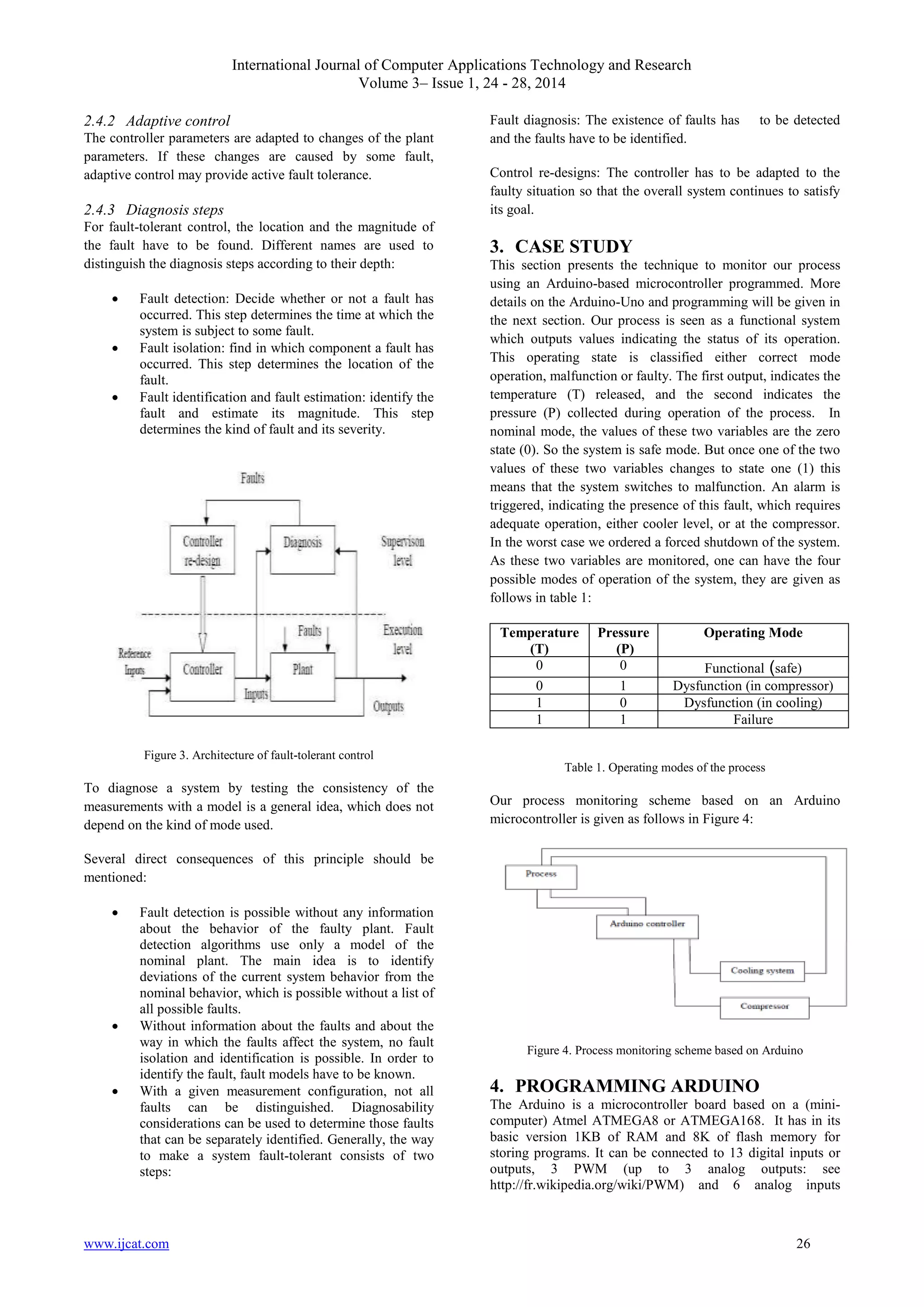
2. FAULT-TOLERANT CONTROL
2.1 Definitions
System: A system is a set of interconnected components.
Each of the components has been chosen or designed by the
system engineer so as to achieve some function of interest. A
function describes what the design engineer expects the
components to perform, independently of how it is performed.
A component performs some function because it has been
designed so as to exploit some physical principles. Which in
general are expressed by some relationships between the time
evolution of some system variables. Such relationships are
called constraints, and the time evolution of a variable is
called its trajectory [10][11].
Fault: A fault in a dynamical system is a deviation of the
system structure or the system parameters from the nominal
situation. Examples for structural changes are the blocking of
an actuator, the loss of a sensor or the disconnection of a
system component.
from permanent damage. A controlled shut-down brings the
technological process into a safe state, if specified conditions
are met. Dedicated actuators stop the process. The over-all
system is then called a fail-safe system.
2.3.2 Reliability
It is the probability that a system accomplishes its intended
function for a specified period of time under normal
conditions. Fault-tolerant control cannot change the reliability
of the plant components, but it improves the reliability of the
overall system, because with a fault-tolerant controller the
overall system remains operational after the appearance of
faults.
2.3.3 Availability
It is the probability of a system to be operational when
needed. Contrary to reliability it also depends on the
maintenance policies, which are applied to the system
components.
2.3.4 Dependability
It lumps together the three properties of reliability, availability
and safety. A dependable system is a fail-safe system with
high availability and reliability.
Figure 1. Fault-tolerant system
2.2 Classification of faults
The faults are often classified as follows:
Plant faults: such faults change the dynamical I/O properties
of the system.
Sensor fault: the plant properties are not affected, but the
sensor readings have substantial errors.
Actuators faults: the plant properties are not affected, but the
influence of the controller on the plant is interrupted or
modified.
Figure 2. Fault diagnosis
2.4 Physical redundancy and analytical
redundancy
Fault tolerance necessitates redundancies. The main
advantage of fault-tolerant control over measures for fault
tolerance is the fact that fault-tolerant control makes
intelligent use of the redundancies included in the system and
in the information about the system in order to increase the
system availability. The analytical redundancy is cheaper than
duplicating all vulnerable components.
Three methods for ensuring fault tolerance are:
2.3 Fault-tolerant control notions
The aims of fault-tolerant control are related to these notions,
which result from different views on faulty systems:
2.3.1 Safety
It describes the absence of danger. A safety system is a part of
the control equipment that protects a technological system
www.ijcat.com
2.4.1 Robust control
A fixed controller is designed that tolerates changes of the
plant dynamics. The controlled system satisfies its goals under
all faulty conditions. Fault tolerance is obtained without
changing the controller parameters. It is, therefore, called
passive fault tolerance.
25](https://image.slidesharecdn.com/ijcatr03011005-140121084023-phpapp02/75/Proposed-Algorithm-for-Surveillance-Applications-2-2048.jpg)
![International Journal of Computer Applications Technology and Research
Volume 3– Issue 1, 24 - 28, 2014
converting 10 bits. In the most common version, the
communication with the computer is via a USB port as shown
in Figure 5. There are several versions of the Arduino,
including a miniaturized version [12]. The card has an internal
software system (editable) and user programs.
Figure 5. Arduino Uno board
Arduino programs are written in C or C++. The Arduino IDE,
as shown in Figure 6, comes with a software library called
“Wiring” from the original Wiring project, which makes
many common input/output operations much easier. Users
only need define two functions to make a runnable cyclic
executive program. The first function is setup (). This function
is launched once at the start of a program that can initialize
settings. The second function is loop (). It is called repeatedly
until the board powers off.
Figure 6. Arduino IDE
Our proposed diagnostic algorithm is defined as follows:
The program is written on the IDE Aduino then it was
compiled. The executable code is loaded to the Arduino
www.ijcat.com
27](https://image.slidesharecdn.com/ijcatr03011005-140121084023-phpapp02/75/Proposed-Algorithm-for-Surveillance-Applications-4-2048.jpg)
![International Journal of Computer Applications Technology and Research
Volume 3– Issue 1, 24 - 28, 2014
board. The system is connected to the Arduino. At this point,
the Arduino board controls the system. The results of the
implementation of our application are given as follows:
The system provides two output values. The first represents
the state of the temperature and the other represents the state
of the pressure, in which the operation of the system
continues. Then the system generates these two values to the
Arduino board, in the pin 13 we find the value indicating the
status of the temperature, zero (0) means nothing to report,
one (1) means that there is an anomaly to report. So, the state
of pin 7 passes to state one (1). It triggers an alarm and
proceeds by actuating the cooler. Pin 12 gives the value
indicating the status of the pressure, zero (0) means nothing to
report, one (1) means that there is an anomaly report. So, the
pin 8 passes to state one (1). It triggers an alarm and proceeds
by actuating the pressure regulator. In both cases the system
switches to malfunction. In the event, the two anomalies occur
together the system switches to state alarmed. In the worst
case, we proceed by a forced shutdown of the system.
5. CONCLUSION
This paper has presented a brief introduction to the fields of
FTC and FDI. An algorithm for monitoring a system was
proposed by using Arduino technology.
As an emerging and active area of research in automatic
control, fault-tolerant control has recently attracted more and
more attention. When a fault occurs in a system, the main
problem to be addressed is to raise an alarm, ideally diagnose
what fault has occurred, and then decide how to deal with it.
The problem of detecting a fault, finding the source/location
and then taking appropriate action is the basis of fault tolerant
control.
In our future work we are interested in neuro-fuzzy
modeling and diagnosis.
6. REFERENCES
[1] L., Jiang.2011. Sensor fault detection and isolation using
system dynamics identification techniques. PhD Thesis.
University of Michigan, USA.
industriel systems based on multiple operating model.
Control Engineering Practice 16,2 (2008) 225-239.
[3] P., Rosa, C., Silvestre, J.S., Shamma, and M., Athans.
2010. Fault detection and isolation of an Aircraft using
Set-Valued Observers. Georgia, USA.
[4] T., Escobet and L., Travé-Massuyès. 1995. Parameter
estimation methods for fault detection and isolation.
Campus de Terrassa, Barcelona, Spain.
[5] Y., Tharrault, G., Mourot, J., Ragot and D., Maquin.
2008. Fault detection and isolation with robust principal
component analysis. Int.J.Appl.Math.Comput.Sci., 2008,
Vol. 18, N°4, 429-442.
[6] M., Fliess, C., Join, and H., Sira-Ramirez. 2006. Closedloop fault-tolerant control for uncertain nonlinear
systems. Ecole plytechnique. Palaiseau, France.
[7] Y., Wang, D., Zhou, S., Joe Qin, and H., Wang. 2008.
Active fault-tolerant control for a class of nonlinear
systems with sensor faults. International journal of
control, automation, and systems, vol.6 n°.3, (2008), pp.
339-350.
[8] Y., Diao, K.M., Passino. 2002. Intelligent fault-tolerant
control using adaptive and learning methods. Control
Engineering Practice 10 (2002) 801-817.
[9] J., Stroustrup, and V.,D., Blonded. 2004. A simultaneous
stabilization approach to (passive) fault tolerant control.
Department of control engineering institute of electronic
systems, Denmark.
[10] M., Staroswiecki, M. Blanke, and N., Eva. 2001.
Concepts and methods in fault-tolerant control. Book.
[11] M., Staroswiecki, M., Blank, M., Kinnaert, J., Lunze.
2006. Diagnosis and fault-tolerant control. Springer.
[12] J.,N., Montagné. 2006. Initiation à la mise en œuvre
matérielle et logicielle d’Arduino. Livret en français,
Centre de Ressources Art Sensitif.
[2] M., Rodrigues, D. Theillol, M., Adama and D., Sauter.
2008. A fault detection and isolation scheme for
www.ijcat.com
28](https://image.slidesharecdn.com/ijcatr03011005-140121084023-phpapp02/75/Proposed-Algorithm-for-Surveillance-Applications-5-2048.jpg)

This paper proposes a diagnostic algorithm for fault detection and isolation (FDI) in technological systems using Arduino technology. It emphasizes the importance of fault-tolerant control (FTC) to maintain system functionality despite component failures, and includes a case study demonstrating the proposed monitoring system's effectiveness. The document outlines various fault types, their classification, and the impact on operational safety and efficiency.