
Recommended
More Related Content
What's hot
What's hot (20)
Similar to 2D Drafting Principles
Similar to 2D Drafting Principles (20)
More from Ashok Mannava
More from Ashok Mannava (20)
Recently uploaded
Recently uploaded (20)
2D Drafting Principles
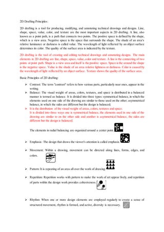
- 1. 2D Drafting Principles: 2D drafting is a tool for producing, modifying, and annotating technical drawings and designs. Line, shape, space, value, color, and texture are the most important aspects in 2D drafting. A line, also known as a point path, is a path that connects two points. The positive space is defined by the shape, which is a view area. Negative space is the space that surrounds the shape. The shade of an area's relative luminance or darkness is called value. The wavelength of light reflected by an object surface determines its color. The quality of the surface area is indicated by the texture. 2D drafting is the tool of creating and editing technical drawings and annotating designs. The main elements in 2D drafting are line, shape, space, value, color and texture. A line is the connecting of two points or point path. Shape is a view area and itself is the positive space. Space is the around the shape is the negative space. Value is the shade of an area relative lightness or darkness. Color is caused by the wavelength of light reflected by an object surface. Texture shows the quality of the surface area. Basic Principles of 2D drafting: Contrast: The term "contrast" refers to how various parts, particularly near ones, appear in the writing. Balance: The visual weight of areas, colors, textures, and space is distributed in a balanced manner is termed as balance. It is divided into three types: symmetrical balance, in which the elements used on one side of the drawing are similar to those used on the other; asymmetrical balance, in which the sides are different but the design is balanced; It is the distribution of the visual weight of areas, colors, textures and space. It is divided into three ways one is symmetrical balance, the elements used in one side of the drawing are similar to on the other side and another is asymmetrical balance, the sides are different but the design is balanced. The elements in radial balancing are organized around a center point. Emphasis: The design that draws the viewer's attention is called emphasis. Movement: Within a drawing, movement can be directed along lines, forms, edges, and colors. Pattern: It is repeating of an area all over the work of drawing. Repetition: Repetition works with pattern to make the work of art appear lively, and repetition of parts within the design work provides cohesiveness. Rhythm: When one or more design elements are employed regularly to create a sense of structured movement, rhythm is formed, and active, diversity is necessary.
- 2. Variety: It is the use of a variety of design components to keep the viewer's attention and move the viewer's eye through and around the drawing. Unity: It is the balance of all parts of the work of drawing, which create a sense of completeness. About AutoCAD AutoCAD software was developed in the year 1982 by Autodesk. AutoCAD is globally used by surveyors, designers, engineers, drafters. Globally, AutoCAD has proven as an efficient and user-friendly program. Commercial drafting and computer-aided design (CAD) software applications are AutoCAD. AutoCAD software is recognized internationally for its remarkable editing capabilities, which make it likely to digitally draw building plans or recreate 3D images. AutoCAD also works on a database of geometric systems, including points, lines, arcs, etc. The user works on the application through the commands; editing or drawing is done from the inbuilt command line. Components of AutoCAD: The designers can create models, sketches, and drawings with AutoCAD. This is next to impossible when done manually. With the introduction to AutoCAD, the user can even model 3D objects with colours & materials that can be applied to various surfaces, making it simpler for the user to anticipate the outcome, which cannot be fulfilled in manual 3D sketches. Creating drawings manually is a time-consuming task. When designers create drawings on a digital platform with computer software, they get the benefit of the application interface. Editing is also easy with AutoCAD as it has many editing commands. AutoCAD is an advanced program that has default commands incorporated in the application. With these commands, the users can edit and change their files without any limitations. Characteristics of AutoCAD AutoCAD is a global application. It is being used globally by product development teams, manufacturing facilities, medical professionals, in educational institutions, by professionals and engineers. 3D modeling and visualization are two main important features of the program. AutoCAD allows the modelers to create powerful 3d models, wireframes, meshes & surfaces by using various 3D tools & commands. AutoCAD is a professional application that has flexibility in design changes and has an auto- specification check feature. The mistakes in the designs or the product can be avoided and can be re-editing as and when required. AutoCAD has the capability to create section planes. These section planes help in achieving cross-sectional views of 3D objects. The users can change, select, or move the section planes to inspect the inner details of 3D objects. AutoCAD helps the user to develop, modify, and design better infrastructure, deliver scalable and feasible building assignments, supervise production finances, and foresee project results.
- 3. Recreating and editing 2D images with their text properties can also be achieved with AutoCAD. AutoCAD drawings can also be linked directly to Microsoft Excel Spread sheets. With this technique, formulas and data from Excel can be imported directly to AutoCAD. This feature is an Auto-Update command. AutoCAD also comes with an SHF text recognition tool that helps users convert text with SHF fonts into the text object. With AutoCAD, the students can even import PDF files for any project reference. 3D models from other CAD applications can also be imported to AutoCAD. The designers can also work on imported online maps or locations. Benefits and limitations of AutoCAD: With AutoCAD, the users get to link their files to multiple platforms; they have the benefit of importing and exporting all kinds of files. The users can even expand the base program through programming; thus, AutoCAD is a versatile application that has standardized in computer designs. AutoCAD also has project managing tools that allow users to share information simultaneously & effectively. The cost of the program is quite high due to its license. The software is a time-consuming application. It has many functions and features which specific and to the point. A powerful computer with good RAM and Hard disk is required for the application to work with processing speed. Applications of AutoCAD: AutoCAD is compatible with other applications like 3D Max. The designers can even import or export DWG & DXG Files to the application. Also, these files can even be exported from AutoCAD to other applications for creating more improved projects & presentations. 3D printers use various file formats that are not supported by all the CAD software. On the other hand, AutoCAD supports these file formats that are preferred by most of the 3D printers. AutoCAD is adaptive to the CAD interface and its usage. AutoCAD allows the professionals to check the workings of the framework within the stage of designing itself. Designers can use this framework for projects & presentations. AutoCAD comprises integrated design layouts of various templates specially designed for architectural planning and infrastructure constructions; the users can work on plans that include creating architectural arrangements for construction purposes without having to master the software. AutoCAD is not only a powerful application but also has a simpler user interface. It comes with a lot of functions and commands that are to the point and without any confusion. AutoCAD is also used in the fashion industry by designers as they can design difficult shapes and designs without any problems. Engineers also use AutoCAD as it incorporates easier drafting tools and helps in modeling engineering designs, blueprints, and other components. With AutoCAD, the engineers can design realistic models with minimum errors. AutoCAD acts as a medium to the users for designing mechanical parts and components for their projects.
- 4. However, many other professions, such as fine artists and mathematicians, may use the program to create visuals for their work. Here are a few other examples of careers that likely use AutoCAD: Interior designers, Electrical drafters, civil drafters, Mechanical drafters, Fashion designers, Graphic designers, Set designers, Process drafters. Drawing Settings: Select options and specify preferences for generaldrawing settings. 1. Click Application button > Options. 2. In the Options dialog box, click a tab and set options as desired. 3. Save the settings: To save the settings and keep working in the dialog box, click Apply. To save the settings and close the dialog box, click OK. Common settings are found in the above Window: Options dialog box. Changes the settings that control colour themes, background colours, crosshairs, grips, default file paths, tooltip display, command line fonts, and the behaviours of many application elements (OPTIONS). Customize User Interface Editor. Controls the tools and command elements on ribbons, toolbars, and menus (CUI).
- 5. UCS Icon dialog box. Controls the appearance of the UCS icon in model space and paper space (UCSICON). Clean screen. Toggles the display of the menu bar, status bar, ribbon, and the Command window when you want to expand the size of the drawing area (Ctrl + 0). View transition settings. Controls whether view transitions are smooth or instantaneous when you pan, zoom, or change from one view to another (VTOPTIONS). Workspaces. Specifies a named user interface environment that contains only the tools that you want displayed (WORKSPACE). The window shows the Main menus on the AutoCAD screen: Menu Bar: The menu bar’s purpose is to supply an application-specific menus which provide access to such functions as opening files, interacting with an application, or displaying help documentation or manuals. Status Bar: The status bar displays the cursor location, drawing tools, and tools that affect your drawing environment. The status bar provides quick access to some of the most commonly used drawing tools. Tool Bars: Basic drawing commands, as well as frequently used advanced drawing commands, are located on the Drawing toolbar. One Drawing toolbar in AutoCAD is built into the tool ribbon, and the second is a floating panel that can be fixed.
- 6. Command Prompt Line: The AutoCAD Command line is like a combined control panel and index of all AutoCAD commands you run and have run on your drawing. When you type a keyboard command, you're using the Command line. It's also the source of prompts that are embedded into AutoCAD commands. Layer status window: Layers are the most important organizing feature available in AutoCAD drawings. To see how a drawing is organized, use the layer command to open the Layer Properties Manager. You can either enter layer in the Command window, or you can click the Layer Properties tool on the ribbon. Layout buttons: Basically, a layout in AutoCAD represents a 2d space where the user can determine the size of the drawing board and edit the title block and view multiple scenes of the object at the same time. Units: Engineers represent units in various ways: feet, meters, etc. To ensure accuracy and eliminate confusion, it is important that the drawing is set in the proper units. To set up your units, type ‘UN’ into your keyboard and then select the ‘ENTER’ key. A dialog box should pop-up on the screen allowing you to specify the unit type and precision for your units. Drawing Tool Bar in AutoCAD: The various AutoCAD tools present to assist in drawing a certain part/component, the most basic types used are: Line, Circle, Arc, Rectangle and Polyline. Line: Line command by choosing the Line tool from the Draw Tool bar, or also invoke the Line tool by entering Line or L at the Command Prompt. You will have to specify the starting
- 7. point of the line by clicking the mouse then you will be prompted to specify the second point. You can terminate the LINE command by pressing ENTER, ESC or SPACEBAR. Poly line: Polylines means many lines. To draw a polyline, you need to invoke the PLINE command. After invoking the PLINE command and specifying the start point and Specify next point or [Arc] specify the endpoint of the second polyline segment or press ENTER to exit the command. Circle: A circle is drawn by using the CIRCLE command. You can draw a circle by using six different tools, i.e., by specifying centre and radius, by specifying center and diameter, by specifying two diametrical ends, by specifying three points on a circle, tangent to two objects, tangent to three objects. Arc: Arc command is used for creating an arc in different types of drawings. Take the arc command and specify the start point by clicking on any point. Specify the endpoint or value where you can connect the arc or end the arc. Rectangle: Draw rectangles by specifying two opposite corners of the rectangle, specifying the area and the size of one of the sides, or specifying the rectangle’s dimensions.
- 8. Drafting Settings dialog box: The various settings are Snap and Grid Right-click on the above icon > and click on Snap Settings. A dialog box will appear, as shown below. We can modify the parameters according to the requirements. Polar tracking It displays the alignment paths as we move the cursor near the defined angles. 90 degrees is considered as the default angle. Right click on the above icon > click on Tracking Settings. A dialog box will appear, as shown below:
- 9. Object Snap Right click on the above icon > click on Object Snap Settings.A dialog box will appear,as shown below. We can select the desired points according to the requirements. It displays the points on the objects, such as midpoints, center point, quadrant point, insertion point, endpoint, etc., which make the drafting and drawing process effective. Center point
- 10. Quadrant point Insertion point 3D Object Snap The 3D Object Snap is used to specify a precise location on the 3D objects. Right-click on the above icon > click on Object Snap Settings> Click on 3D Object Snap. A dialog box will appear, as shown below. It displays the points on the objects, which make the drafting and modelling process effective, such as vertex, edge, corner, node, etc. The 3D Object Snap option appears after the Object Snap option.
- 11. Dynamic Input The Dynamic Input in AutoCAD includes a command interface, which is provided near the cursor. The command interface is placed near the cursor on the viewport of the drawing area. Right-click on the above icon > click on Dynamic Input Settings. A dialog box will appear, as shown below Quick Properties:To implement these properties, type QP or quick properties on the command line or command prompt and press Enter. The Quick Properties command is used to display all the properties of the selected object.
- 12. SelectionCycle To implement, type SELECTION CYCLING on the command line or command prompt, and press Enter. It controls the display behavior of the objects, such as overlapping objects. Object selection methods: Before you start to use the AutoCAD Modify commands, you need to know something about selecting objects. All of the Modify commands require that you make one or more object selections. AutoCAD has a whole range of tools which are designed to help you select just the objects you need. This tutorial is designed to demonstrate the use of many of the selection options. As with so many aspects of AutoCAD, developing a good working knowledge of these options can drastically improve your drawing speed and efficiency. Selecting Objects by Picking To select an object, place the pickbox over a part of the object and left-click the mouse. When the object has been picked it is highlighted in a dashed line to show that it is part of the current selection and the command line reports "1 found". You will now see the "Select objects" prompt on the command line again. At this point you can continue adding more objects to the current selection by picking them or you can press or the Space Bar to complete the selection. When you pick one or more objects in response to the "Select objects" prompt, you are effectively creating a selection set. Selection sets are an important concept in AutoCAD because they can be used to great effect, especially when drawings become large or complicated. Window selection: The Window option is invoked by typing W in response to the "Select objects" prompt. Window allows you to define a rectangle using two points in exactly the same way as the RECTANGLE command. Once the window is defined, all objects which lie entirely within the window will be selected. Command: (start one of the Modify commands such as ERASE) Select objects: W First corner: (pick first corner) Specify opposite corner: (pick second corner) Select objects: (at this point you can either select more objects or to complete the selection set and continue with the current command.)
- 13. Crossing window selection The Crossing Window option is invoked by typing C at the "Select objects" prompts and is a variation of the Window command. The command sequence is exactly the same but objects are selected which lie entirely within the window and those which cross the window border. Implied Windowing Although you can explicitly invoke the Window and Crossing Window selection boxes by entering W or C at the keyboard when prompted to "Select objects", in practice this is rarely done. Both of these selection options are so commonly used that AutoCAD provides a method of implied windowing so that you don't have to use the keyboard at all. You can test this out without using any command. If you pick a point in space on the graphic window, you will notice that AutoCAD automatically assumes that you want to define a selection window and uses the pick point as the first point of that window. If you move the cursor to the right of the pick point you will get a Window selection box. If you move the cursor the left you will get a Crossing Window selection box. With a little bit of practice the use of implied windowing can make the whole drawing process very efficient and you will rarely find yourself having to explicitly invoke the window selection options from the keyboard. Fence selection The Fence option allows you to draw a multi-segment line, like a Polyline. All objects which cross the fence will be selected. The Fence option is invoked by typing F at the "Select objects" prompt. Selectobjects: F Firstfencepoint: (pickfirstpoint) Specifyendpointoflineor[Undo]: (picksecondpoint) Specify endpoint of line or [Undo]: (pick another point or to end fence selection) Select objects: ( to complete the selection set or add more objects)
- 14. Window polygon selection: The Window Polygon option, invoked by typing WP is similar to the Window option except that you can define an irregular polygon shape within which objects will be selected. As with the Window option, only objects which fall entirely within the polygon will be selected. A polygon is formed by picking at least three points. Command: (startoneoftheModifycommands) Selectobjects: WP Firstpolygonpoint: (pickfirstpoint) Specifyendpointoflineor[Undo]: (picksecondpoint) Specifyendpointoflineor[Undo]: (pickthirdpoint) Specify endpoint of line or [Undo]: (pick another point or to end polygon selection) Select objects: ( to complete the selection set or add more objects) Crossing polygon selection The Crossing Polygon option can be used in exactly the same way as the Window Polygon option but it has the same selection criteria as the Crossing Window option, i.e. objects will be selected if they fall entirely within or touch the polygon boundary. This option is invoked by typing CP at the "Select objects" prompt.
- 15. Note: Lines, polygons and windows drawn using the selection options do not exist as drawing objects. Once the selection has been made they disappear. Object cycling When drawings become complicated it is sometimes difficult to select the particular object you want because it is either very close to or overlies another object. In such a case it may happen that the other object is selected and not the one you want. Object cycling is designed to overcome this problem. If you make a pick whilst holding the Control (Ctrl) key down, AutoCAD will respond with "<Cycle on>". If you continue to pick, each object near the pick point is highlighted in rotation. Just keep picking until the object you want is highlighted, then right-click or , AutoCAD responds "<Cycle off>", the required object is added to the selection set and you can continue to select more objects as normal. Selecting all objects The All option is invoked by typing ALL at the "Select objects" prompt. You can use this option to select all the objects in the current drawing, no picking is required. Objects on Locked or Frozen layers are not selected but objects on layers which are simply turned off are selected. Adding and Removing objects AutoCAD provides two methods for adding and removing objects to and from a selection set. As you know, objects can be added to a selection set simply by picking them or by using one of the methods outlined above. You can remove selected objects from a selection set just as easily by shift picking. If you hold the Shift key down on the keyboard while picking a selected object, that object will be deselected (removed from the current selection set). You can tell when a selected object has been deselected because it is no longer highlighted. You can remove more than one object at a time by holding down the Shift key while using implied windowing. However, none of the other selection options which require keyboard input will work using the shift pick method. If you need to remove a more complex selection from the current selection set you should use the Remove option to switch to Remove mode. If you enter R at the "Select objects" prompt, AutoCAD will respond. Remove objects: Objects now picked or selected using any of the above methods will be removed from the current selection set. When you have finished removing objects, you can return to Add mode by entering A at the "Remove objects" prompt. You can use any combination of picking, selection options and add/remove modes to define your selection set. Once you are happy that you have selected all the objects you need, just hit to complete the selection process and to continue with the current command. When you feel confident with the basic selection tools, have a look at the Advanced Selection tutorial to find out how to use AutoCAD's advanced selection tools for creating complex selection sets. MODIFYING ENTITIES
- 16. Perform editing operations such as Extend, Copy, Mirror, Rotate, Erase, Offset, Move, Array, Scale, Fillet and Explode on the objects in a drawing. The most common of these tools are located on the Modify panel of the Home tab. Take a minute to look through them. Erase To erase or delete any entities in the drawing we can use ERASE command. Shortcut for ERASE command is E. Enter E at command prompt and press enter. It will ask you to select objects to erase. Select the objects you want to erase. If you want to remove any objects from selection press shift key and select again to remove them from the selection. Now press enter to finish the command We can also delete entities using Delete key on the keyboard. Select the entities to be deleted and press Delete key on the keyboard. To remove entities from selection use shift selection. Copy and move Copy: To copy one or more objects we have to select the objects to be copied and then we must specify from point and to point. If you want to make multiple copies then you have to provide multiple to points. Shortcut for COPY command is CO or CP. Enter CO or CP at command prompt and press enter. Now select objects to be copied and press enter. Now pick base point (From point). Then pick second point (To Point). If you want to make multiple copies, pick as many points as you wish. Press enter to finish the copy command. Move To move one or more objects we have to select the objects to be moved and then we must specify from point and to point. Shortcut for MOVE command is M. Enter M at command prompt and press enter. Now select objects to be moved and press enter. Now you must pick base point (From point) to move objects. Then you must pick Second point (To point) to finish the move command. Distance Method
- 17. Two Points Method Create Multiple Copies
- 18. Offset We can create duplicate entities at required distance using OFFSET command. Shortcut for OFFSET command is O. Enter O at command prompt and press enter. Now enter offset distance. You can pick two points. The distance between those two points will be taken as offset distance. Now select the object to offset. (Only one at a time) Then pick a point on side to offset. You may get a preview of new object. If you are about to offset a closed object, and if the offset distance is invalid, then it will show a error mark as preview. Most models include a lot of parallel lines and curves. Creating them is easy and efficient with the OFFSET command. Click the OFFSET tool or enter O in the Command window. Trim and Extend Trim: Shortcut for TRIM command is Tr. Enter TR at command prompt and press enter. Now you must select Cutting Edges up to which objects to be trimmed. Then press enter to finish selecting cutting edges. Now select objects to be trimmed. You can use selection options provide in prompt. If anything went wrong, you can use Undo option. Extend: Shortcut for EXTEND command is EX. Enter EX at command prompt and press enter. Now you must select Boundary Edges up to which extension has to happen. Then press enter to finish selecting boundary edges. Now select objects to be extended. You can use selection options provided in prompt. If anything went wrong, you can use Undo option.
- 19. Mirror MIRROR command will create a mirror copy of selected objects. For this we have to give two points of mirror line. Shortcut for MIRROR command is MI. Enter MI at command prompt and press enter. Now select objects to be mirrored and press enter. Now pick first point on mirror line. Then pick second point on mirror line. Now it will ask, do you want to Erase source objects? [Yes/No] <N>: If you want to erase source objects type in Y otherwise type in N and press enter. Rotate Shortcut for ROTATE command is RO. Enter RO at command prompt and press enter. Now select objects to be rotated. Then pick a basepoint about which objects to be rotated. Then enter rotation angle. You can pick a point. It will calculate angle between basepoint and second point. While specifying rotation angle we get Copy and Reference options. Copy option will create a copy of selected objects at given angle. Reference option will read current angle (Reference angle) and new angle. Reference: 1. After picking base point, it would ask for rotation angle. Then enter R at command prompt. 2. Now enter current angle of selected object. If you do not know it, then you can pick two points which will specify current angle. 3. Then enter new angle. Again if you do not know, you can pick two points which will specify new angle. Scale (Scale up/down objects): SCALE command is used to increase or decrease the size of selected objects. Shortcut for SCALE command is SC. Enter SC at command prompt and press enter. Then select objects to be scaled. Now pick a basepoint. Then enter scale factor.
- 20. If you enter 2 as scale factor, then object’s size will be doubled. If you enter 0.5 as scale factor, then object’s size will be halved. While specifying scale factor we get Copy and Reference options. Copy option will create a copy of selected objects with given scale factor. Reference option will read current length (Reference Length) and new Length. Reference: After picking base point, it would ask for scale factor. Then enter R at command prompt. Now enter current length of selected object. If you do not know it, then you can pick two points which will specify current length. Then enter new length. Again if you do not know, you can pick two points which will specify new length. Break: Shortcut for BREAK command is BR. Enter BR at command prompt and press enter. Now select the object to break. Notice that the point used to select object will be taken as startpoint for break. Then it will ask to specify second break point. But you have an option to specify First point. To specify first point, enter F at command prompt and pick first point. Then pick second break point. Fillet: FILLET command will create an arc with given radius between two objects. You can fillet arcs, circles, ellipses, elliptical arcs, lines, polylines, rays, splines, and xlines. Shortcut for FILLET command is F. Enter F at command prompt and press enter. It will ask to select first object. But check Current Settings in command response area. If the radius is zero, then even if you select first and second object, nothing will happen. To change radius, enter R at command prompt and press enter It will ask for radius. Enter radius value. And then select first and second objects. By default fillet command will trim lines after creating fillet arc. If you do not want to trim after fillet, then take Trim option by entering T at command prompt. Then enter N (No Trim). Now proceed to select objects. Chamfer: A chamfer connects two objects with an angled line. It is usually used to represent a beveled edge on a corner. You can chamfer Lines, Polylines, Rays, Xlines. Shortcut for CHAMFER command is CHA. Enter CHA at command prompt and press enter. It will ask to select first line. But check Current Chamfer distances in command response area. If Chamfer distances are zero, then no chamfer will be created. To change Chamfer distances, enter D at command prompt and press enter. Now enter first chamfer distance. Then enter second chamfer distance. First and second chamfer distances can be same or varying. Now select first line and then second line. By default chamfer command will trim lines after creating chamfer line.
- 21. If you do not want to trim after chamfer, then take Trim option by entering T at command prompt. Then enter N (No Trim). Now proceed to select lines. Explode The EXPLODE command (enter X in the Command window) disassociates a compound object into its component parts. You can explode objects such as polylines, hatches, and blocks (symbols). After you explode a compound object, you can modify each resulting individual object. Stretch You can stretch most geometric objects. This lets you lengthen and shorten parts of your model. For example, this model might be a gasket or the design for a public park. Use the STRETCH command (or enter S in the Command window) and select the objects with a crossing selection as shown below (1 and 2). The crossing selection is mandatory—only the geometry that is crossed by the crossing selection is stretched. Then click anywhere in the drawing area (3), move the cursor to the right, and enter 50 as the distance. This distance might represent millimeters or feet. Array [ Rectangular/Polar/Path ]: Array is a command used to draw a group of entities in a single step. For example you have a circle in the drawing. And you want to draw same size of circles in some rows and columns likewise in the manner of a matrix. Or you may want to place same size of circles around the periphery of a big circle. Or you may want to place same size of circles along a path (polyline). In all these cases array command is very useful. Shortcut for array command is AR. I have observed so many students typing in ARR at command prompt which is command for Action Recorder. Please use AR only. Draw a small circle with radius 1 or 2 to proceed with array command.
- 22. Rectangular Array: Enter AR at command prompt. It will ask to select objects. Select the circle and press enter. Now you will have three options at prompt [Rectangular/PAth/POlar]. Let us use Rectangular method. Type R at prompt. Now automatically some rows and columns of circles are created without asking us. Don’t worry. The command is still in progress. To change rows, type R at command prompt and enter required number of rows and the distance between rows. Now you will be asked to Specify the incrementing elevation between rows, just press enter, because it is a 3D concept, you can not observe any change in the array if you give a value or not. To change columns type COL at command prompt and enter required number of columns and the distance between columns. Once you got the required number of objects, just press enter to finish the command. Polar Array: Before using this command draw a big circle with a radius 20. Then draw another circle with radius 2, at any quadrant of big circle. Make sure that quadrant object snap is on. Now enter AR at command prompt. It will ask to select objects. Select the small circle and press enter. Now you will have three options at prompt [Rectangular/PAth/POlar]. We shall take polar method. Type PO at prompt. Now it will ask to Specify center point of array. Pick center point of big circle. Now automatically some instances of small circle are drawn along periphery of the big circle. To change number of small circles, type I for (items) and enter required number of items. If you want to fill all these small circles within 180 degrees then type F at prompt and enter 180. You can observe the change that all small circles are filled within 180 degrees. Now press enter to finish array command. Note:Draw a horizontal line instead of small circle and then use polar method. Activate rotate items option and select Yes/No options and observe changes. Path Array: Before using this command draw a polyline. We shall use this as a path curve. And a small circle at the start point of polyline. Now enter AR at command prompt. It will ask to select objects. Select the small circle and press enter. Now you will have three options at prompt [Rectangular/Path/Polar]. We shall take path option. Type PA at prompt and press enter. It will ask to select path curve. Select the polyline. Automatically few numbers of small circles are drawn along the path curve. To change the distance between circles, type I for (items) and enter distance between circles, and just press enter when you are asked to enter number of items. Again press enter to finish the command. CONTROLLINGDISPLAY ANDVIEWS As you edit your drawing, you can control the drawing display and move quickly to different areas of your drawing while you track the overall effect of your changes. You can zoom to change magnification or pan to reposition the view in the drawing area; save a view and then restore it when you need to plot or refer to specific details; or display several views at one time by splitting the screen into several tiled viewports.
- 23. Zoom: Zoom command increases or decreases the apparent size of the objects. Shortcut for ZOOM command is Z. Enter Z at command prompt and press enter. We will get [All/Center/Dynamic/Extents/Previous/Scale/Window/Object] options. All option brings entire drawing into display at once. If the limits are bigger than objects then limits will be displayed. If objects are bigger than limits then objects are displayed as large as possible. Extents option displays current drawing content as large as possible. Previous option restores previous view. Window option allows us to pick two corners of a window and fits that window to the screen. Object option allows us to select objects to be displayed as large as possible. Pan: To move the entire drawing sheet we can use PAN command Shortcut for PAN command is P. Enter P at command prompt. Now a hand symbol will appear on the screen. Click your left mouse button and drag the drawing as you wish. To come out of the PAN command press Escape key or right click and select Exit. Display or Hide Dynamic Constraints You can hide all dynamic constraints to reduce clutter when you want to work with geometric constraints only, or when you need to continue other work in the drawing. You can turn on their display when needed from the ribbon or with the DCDISPLAY command. By default, if you select an object associated with a hidden dynamic constraint, all dynamic constraints associated with that object are temporarily displayed. You can display or hide the dynamic constraints for all objects or for a selection set. Display or Hide Annotational Constraints You control the display of annotational constraints as you would with dimension objects—you assign them to a layer and turn the layer on or off as needed. You can also specify object properties for annotational constraints such as dimension style, color, and lineweight. Viewport controls: Viewport controls are displayed at the top-left corner of each viewport, and provide a convenient way of changing views, visual styles, and other settings.
- 24. In model space,you can split the drawing area into one or more rectangular areas called model space viewports. Viewports are areas that display different views of your model. In large or complex drawings, displaying different views reduces the time needed to zoom or pan in a single view. Errors that you might miss in one view might be visible in another. Below are severalexamples of model space viewport configurations. You can save and restore viewport configurations by name with the VPORTS command. When you display multiple viewports, the one that is highlighted with a blue rectangle is called the current viewport. Commands that control the view, such as panning and zooming, apply only to the current viewport. Commands that create or modify an object are started in the current viewport, but the results apply to the model and can be visible in other viewports. You can start a command in one viewport and finish it in a different viewport. You can make any viewport the current one by clicking in it. Modify Model Space Viewports You can modify the size, shape, and number of model space viewports in a viewport configuration: Choose from severalviewport configurations by clicking the [+] or [-] control in the top-left corner of a viewport. Drag the boundaries of viewports to adjust their size.
- 25. Press CTRL while dragging viewport boundaries to display the green splitter bar and create new viewports. Alternatively, you can drag the outermost splitter controls. Drag a viewport boundary onto another boundary to remove a viewport. 2D Wireframe You can click within each of the three bracketed areas to change the settings. Click the + or - to display options for maximizing the viewport, changing the viewport configuration, or controlling the display of navigation tools. Click Top to choose between severalstandard and custom views. Click 2D Wireframe to choose one of severalvisual styles. Most of the other visual styles are used for 3D visualization. CREATINGDIMENSIONS AND DIMENSION STYLES Dimension To place a horizontal dimension, enter DIMHOR at command prompt. Pick two points for extension line origins and drag the cursor to locate the dimension and pick the location. To place a vertical dimension, enter DIMVER at command prompt. Pick two points for extension line origins and drag the cursor to locate the dimension and pick the location. To place aligned dimension, enter DIMALI at command prompt. Pick two points for extension line origins and drag the cursor to locate the dimension and pick the location. To place a radius dimension, enter DIMRAD at command prompt. Select the arc or circle, then drag the cursor to locate the dimension and pick the location. To place a diameter dimension, enter DIMDIA at command prompt. Select the arc or circle, then drag the cursor to locate the dimension and pick the location. Baseline Dimension:
- 26. Place a horizontal or vertical dimension to use in baseline dimension. Now enter DIMBASE at command prompt. You must observe, automatically a dimension starting from previous dimension start point will appear and it will ask you to pick second extension line origin point to draw the new dimension. Otherwise it would ask you to select base dimension. Select the base dimension first extension line from which new dimension should start. And then pick second extension line origin for new dimension. From now, you need to pick only second extension line origin for every new baseline dimension. No need to pick first extension line origin. That will be automatically selected. Continuous Dimension: Place a horizontal or vertical dimension to use in continuous dimension. Now enter DIMCON at command prompt. You must observe, automatically a new dimension will start from the end point of previous dimension. Otherwise it would ask you to Select continued dimension. Select continued dimension from which new dimension should start. From now you need to pick second extension line origin for every new continued dimension. No need to pick first extension line origin. That will be automatically selected. Multi Leader: Shortcut command for Multi leader is MLD. Enter MLD at command prompt. It will ask you to specify leader arrowhead location. Just pick a point on screen. Now it would ask to specify leader landing location. Pick another point on screen. Automatically a Mtext command will continue. Just type in the required text and select OK. A multi leader is drawn. We can add multiple leaders. To do that, select the new leader. And hover the cursor on landing point. You would get a pop up menu. Select Add Leader and pick points to place multiple leaders. Creating AutoCAD Dimension style: When using dimensions we constantly have to modify the standard style from AutoCAD to fit our needs. Creating a dimension style is one of the answers to this problem. By creating a dimension style we can have different styles for specific scales,etc... Plus we can always transfer the style to another drawing or save it as a template for future use. Not to mention, that also saves you time. 1. Click Home tab Annotation panel Dimension Style. Find 2. In the Dimension Style Manager, click New. 3. In the Create New Dimension Style dialog box, enter a name for the new dimension style, and click Continue. 4. In the New Dimension Style dialog box, click each tab,and make any changes for the new dimension style.
- 27. 5. Click OK and then Close to exit the Dimension Style Manager. A dimension style is a named collection of dimension settings that controls the appearance of dimensions, such as arrowhead style, text location, and lateral tolerances. You create dimension styles to specify the format of dimensions quickly, and to ensure that dimensions conform to industry or project standards. When you create a dimension, it uses the settings of the current dimension style. If you change a setting in a dimension style, all dimensions in the drawing that use the style update automatically. You can create dimension sub styles that use specified settings for different types of dimensions. You can override a dimension style with dimension settings that deviate from the current dimension style. All dimension styles in your drawing are listed in the Dimension Style drop-down. you can control dimension line properties including color, lineweight, and spacing. Specify color and lineweight for visual effect and plotting Suppress the dimension line or, if the dimension line is broken by text, one or both halves Control the spacing between successive dimension lines in baseline dimensions
- 28. Control the distance by which the dimension line extends beyond the extension lines for architectural tick (oblique stroke) arrowheads You can control extension line properties including color, lineweight, overshoot, and offset length. Specify color and lineweight for visual effect and plotting Suppress one or both extension lines if they are unnecessary, or if there is not enough space Specify how far beyond from the dimension line the extension line extends (overshoot) Control the extension origin offset,the distance between the extension line origin, and the start of the extension line Specify a fixed length for extension lines, as measured from the dimension line toward the extension line origin Specify a noncontinuous linetype, typically used for centerlines
- 29. Modify the angle of the extension lines of a selected dimension to make them oblique Fixed-Length Extension Lines You can specify a dimension style that sets the total length for extension lines starting from the dimension line toward the dimension origin point. The extension line offset distance from the origin will never be less than the value specified by the DIMEXO system variable. You can choose from many standard types of arrowheads,or you can create your own arrowheads. Additionally, you can Suppress the display of arrowheads,or use one arrowhead only Apply a different type of arrowhead to each end of a dimension line Control the size of arrowheads Flip the direction of an arrowhead using the dimension shortcut menu
- 30. You can locate dimension text manually and specify its alignment and orientation. The program comes with severaljustification settings that facilitate compliance with international standards, or you can choose your own location for the text. Many of the settings are interdependent. Example images in the Dimension Style Manager are updated dynamically to illustrate how text appears as you change the settings. Align Dimension Text Whether text is inside or outside the extension lines, you can choose whether it is aligned with the dimension line or remains horizontal. The following examples show two combinations of these options. The default alignment is horizontal dimension text, even for vertical dimensions. Position Dimension Text Horizontally The position of the text along the dimension line in relation to the extension lines is referred to as text placement. To place text yourself when you create a dimension, use the Place Text Manually option on the Modify/New Dimension Style dialog box, Fit tab. Use the text placement options to automatically place text at the center of the dimension line, at either extension line, or over either extension line.
- 31. First and second extension lines are defined by the order in which you specified the extension line origins when you created the dimension. For angular dimensions, the second extension line is counterclockwise from the first. In the following illustrations, 1 is the first extension line origin and 2 the second. If you place text manually, you can place the dimension text anywhere along the dimension line, inside or outside the extension lines, as you create the dimension. This option provides flexibility and is especially useful when space is limited. However, the horizontal alignment options provide better accuracy and consistency between dimensions. Position Dimension Text Vertically The position of the text relative to the dimension line is referred to as vertical text placement. Text can be placed above or below or centered within the dimension line. In the ANSI standards, centered text usually splits the dimension line. In the ISO standards, it is usually above or outside the dimension line. For example, ISO standards permit angular dimension text to appear in any of the ways shown.
- 32. Other settings, such as Text Alignment, affect the vertical alignment of text. For example, if Horizontal Alignment is selected, text inside the extension lines and centered within the dimension line is horizontal, as shown in the leftmost illustration above. The text is horizontal even if the dimension line is not itself horizontal.