Downloaded 284 times
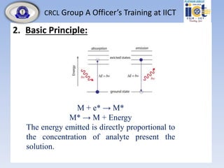
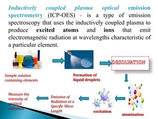
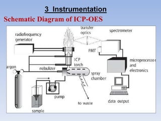
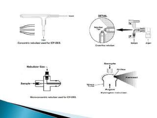
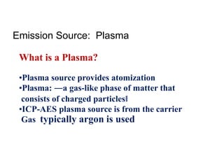
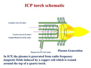
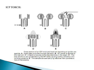
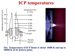
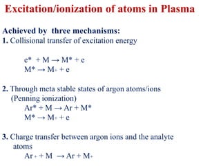
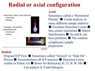
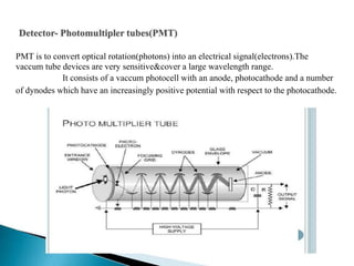
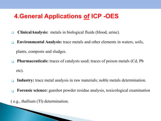
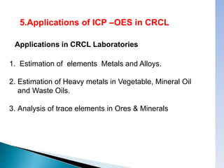
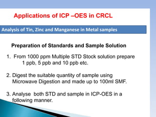
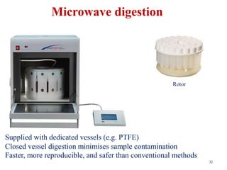
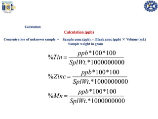

This document summarizes a training presentation on inductively coupled plasma-optical emission spectroscopy (ICP-OES) given to CRCL Group A officers. The presentation covers the basic principles and instrumentation of ICP-OES, including sample introduction using nebulization, plasma generation using a radio frequency coil, excitation of atoms in the plasma, and emission detection using a photomultiplier tube. Applications discussed include clinical, environmental, pharmaceutical and industrial analysis, as well as specific examples analyzing metals in CRCL samples such as estimating elements in alloys and heavy metals in oils and minerals. The document provides details on sample and standard preparation, microwave digestion of samples, and calculations for determining unknown sample concentrations from ICP-O


![FOURIER -TRANSFORM INFRARED SPECTROMETER [FTIR]](https://cdn.slidesharecdn.com/ss_thumbnails/ftir-160604063055-thumbnail.jpg?width=640&height=640&fit=bounds)


