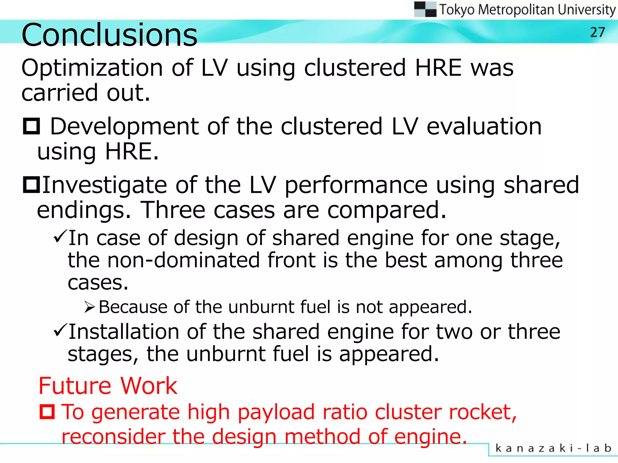
This document summarizes research on the design optimization of a launch vehicle concept using a clustered hybrid rocket engine for future space transportation. The researchers developed a design methodology for a launch vehicle with clustered hybrid rocket engines and investigated combinations of unit engines. Their objectives were to maximize payload to gross weight ratio and minimize gross weight. They defined four design cases and used multi-objective genetic algorithms and data visualization techniques to optimize the design variables. The results showed that a design with optimized engines for each stage performed best by avoiding excess unburnt fuel from shared engines across stages. Future work could further reduce unburnt fuel and improve payload ratio.


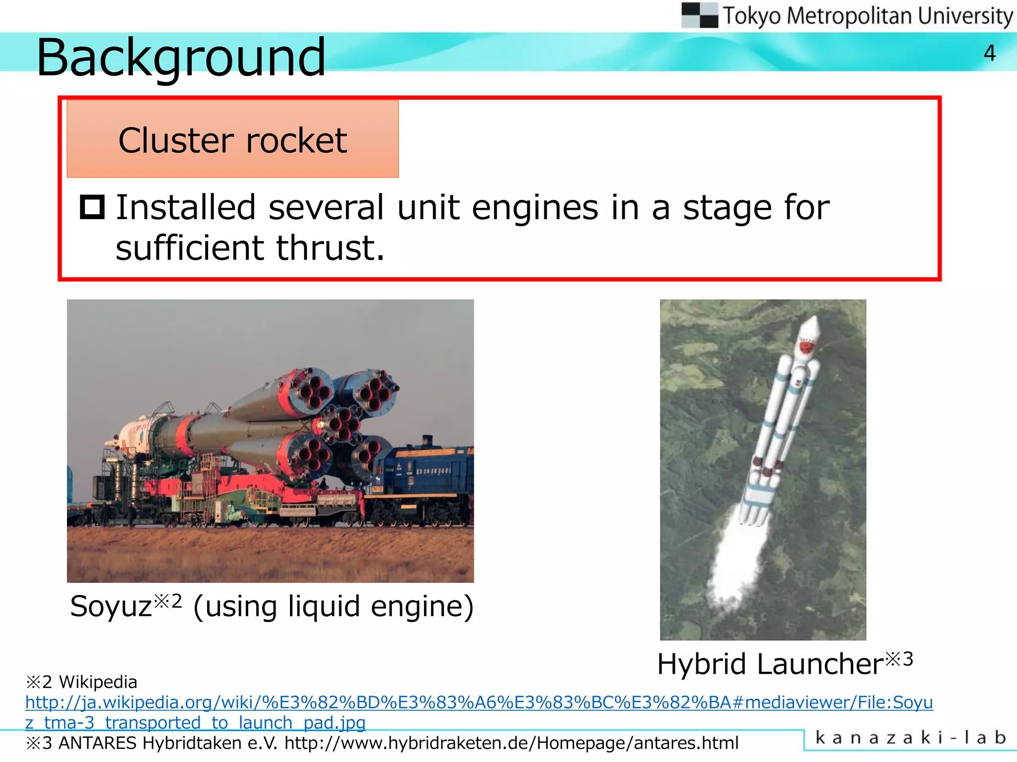
![Background
Advantage of hybrid
rocket engine(HRE)
Higher safety
Lower cost
Lower environmental
impact
Hybrid rocket has possibility
to be next generation
efficient launch vehicle.
Space ship two※1
※1,VirginGalactic http://www.virgingalactic.com/
※2, [1] Y. Kitagawa, K. Kitagawa, M. Nakamiya, M. Kanazaki, T.
Shimada, T JSASS, 55(2012), R4
3
Our previous research※2
Development of multi-
disciplinary design methodology
Optimization for single stage and
three stage launch vehicle](https://image.slidesharecdn.com/141007icfdver6-150616061126-lva1-app6891/75/ICFD2014-3-2048.jpg)

![Fuel Design
Regression rate rport is calculated by
n
tport Gatr ][)( )(0
8
.
.
Radius of fuel is calculated by rport and tb
(tb is design variables) .
G0(t) Oxidizer mass flux
a Fixed number decided by kind of fuel
n
β Simulating fuel circling
.](https://image.slidesharecdn.com/141007icfdver6-150616061126-lva1-app6891/75/ICFD2014-8-2048.jpg)
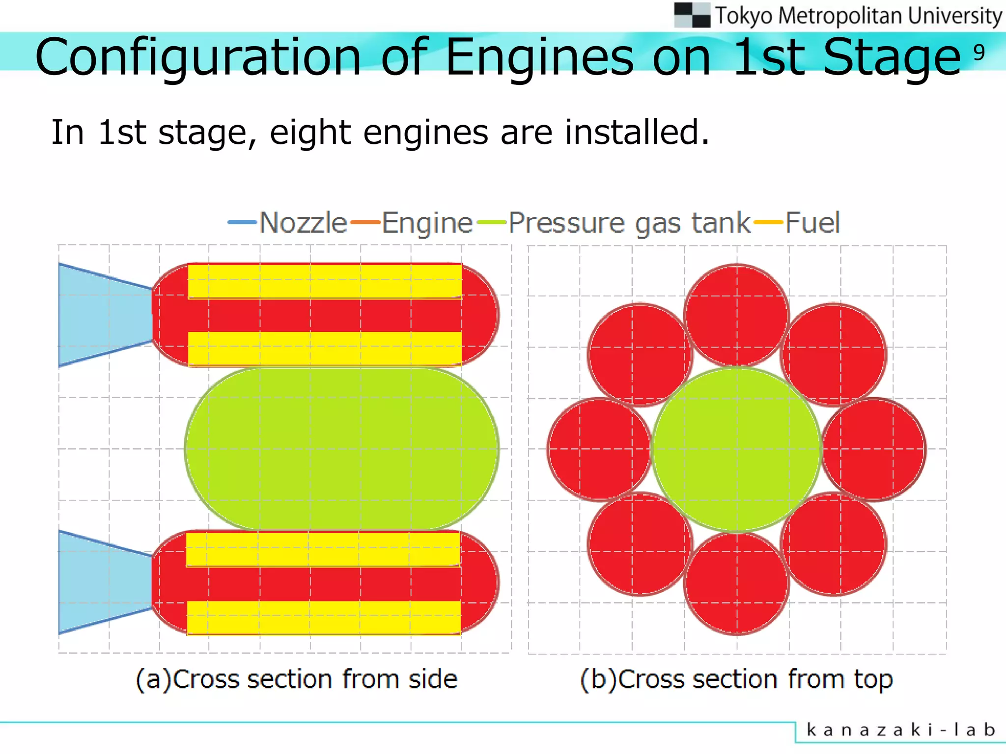

![Cluster Rocket Design Method
Evaluation of rocket radius
Radius of 2nd and 3rd stage exterior wall is equal to
radius of 2nd stage.
Radius of 1st stage is calculated independently.
11
Kind of fuel and oxidizer: Fuel…FT0070 Oxidizer…O2
FT0070
spec
Chemical formula Density[kg/m3] Index n Coefficient a
C35H72 910.0 0.3905 0.1561
n
tport Gatr ][)( )(0](https://image.slidesharecdn.com/141007icfdver6-150616061126-lva1-app6891/75/ICFD2014-11-2048.jpg)


![Result of Design Optimization
0.0
0.2
0.4
0.6
0.8
1.0
1.2
1.4
0.0 2.0 4.0 6.0 8.0 10.0 12.0 14.0 16.0 18.0 20.0 22.0 24.0 26.0 28.0 30.0
Mtot/Mpay[%]
Mtot[ton]
Case1 Case2 Case3 Non-clustered rocket
Trade off can be shown between two objective functions in each case.
Case1 show similar result as non-clustered case.
Case3 which employs same shared engine for each stage achieves
less than half performance compared with Case1.
Unburnt fuel is appeared when one engine design is shared in
two or three stages.
Optimum
Direction
20
Des1 Des0
Des2
Des3
Mpay=100[kg]](https://image.slidesharecdn.com/141007icfdver6-150616061126-lva1-app6891/75/ICFD2014-20-2048.jpg)
![Comparison from Pareto Solutions
Des1 has slender engines.
Des1 and Des2 use small engine in 3rd stage.
↔ Des3 uses largest engine in 3rd stage.
21
Length Radius
18.46[m] 0.60[m]
Length Radius
21.62[m] 0.59[m]
Length Radius(1st) Radius(2nd)
16.64[m] 1.42[m] 0.79[m]
Length Radius(1st) Radius(2nd)
14.83[m] 1.22[m] 0.68[m]
Des0
Des1
Des3
Des2](https://image.slidesharecdn.com/141007icfdver6-150616061126-lva1-app6891/75/ICFD2014-21-2048.jpg)


![Comparison of payload 100kg Rocket(Isp) 24
220
230
240
250
260
270
280
290
300
310
320
0 50 100 150 200 250 300 350 400 450
Isp[s]
Time[s]
While Des3 achieves the highest thrust in all stage, Isp of
3rd stage is the lowest.
Engines of Des3 are not only optimized for 3rd stage.
2nd stage of Des1 achieves the lowest Isp.
The efficiency is limited because the radius of 1st stage is
small.](https://image.slidesharecdn.com/141007icfdver6-150616061126-lva1-app6891/75/ICFD2014-24-2048.jpg)

![Comparison of Payload 100kg Rocket(Numerical Value)
Mtot
[ton]
Mpay/Mtot
[%]
Des1 9.31 1.10
Des2 13.3 0.75
Des3 15.5 0.64
Payload ratio of Des3 is 0.5% less than Des1.
Because of unburnt fuel, total mass of Des3 become heavy.
Fuel Filling Ratio
1st stage 2nd stage 3rd stage
Des1 63[%] 80[%] 93[%]
Des2 86[%] 86[%] 88[%]
Des3 84[%] 84[%] 84[%]
Fuel filling ratio of Des1 is the smallest in 1st stage.
Des1 has slender engines to reduce aerodynamic drag.
Fuel filling ratio of Des2 and Des3 are high.
Because of the appearance of the unburnt fuel, payload
ratio of Des2 and 3 becomes lower than Des1.
It is also required to reduce unburnt fuel.
→(Future work)Addition of objective function objective function:
Minimize unburnt fuel
26
Fuel Filling Ratio=Area of fuel/Area of chamber](https://image.slidesharecdn.com/141007icfdver6-150616061126-lva1-app6891/75/ICFD2014-26-2048.jpg)