1) Researchers developed a small-scale hybrid rocket thruster using hydrogen peroxide as the oxidizer. The thruster was designed to produce 40-50N of thrust.
2) High density polyethylene was selected as the fuel based on its availability and to maintain a steady thrust level over the 10 second planned burn.
3) Initial calculations estimated the thruster would produce 42N of thrust with an initial oxidizer to fuel ratio of 6 using a 5mm port diameter in the polyethylene fuel grain. The design was aimed to demonstrate hydrogen peroxide hybrid rocket technology.
![DEVELOPMENT OF A SMALL-SCALE HYBRID THRUSTER USING
HYDROGEN PEROXIDE AS THE OXIDISER
G.T. Roberts, A.J. Musker*, D. Beechey, N. El-Batal, B. Profir, N. Spencer, N. Tenev, M. Wills
University of Southampton, UK
*
University of Southampton and Managing Director, DELTACAT Ltd, UK
INTRODUCTION
The growing interest, in Europe and elsewhere, of
alternative, non-toxic (“green”) rocket propellants
has been stimulated recently by the placing of
hydrazine on the REACH list of substances that will
be banned for industrial applications in Europe in due
course. One possible alternative propellant that has
been the subject of renewed interest recently is
hydrogen peroxide. Once decomposed
exothermically, high concentration hydrogen
peroxide (often known as high test peroxide, or HTP)
can act as a monopropellant, or as the oxidiser in a
hybrid or bi-propellant thruster.
Previous collaborative work conducted by the
University of Southampton and DELTACAT Ltd
with HTP thrusters has included the successful
development of a 20N-class monopropellant thruster
[1], led by the University of Southampton, and a 150
N monopropellant thruster and 300N bi-propellant
thruster [2], led by DELTACAT Ltd. We have now
embarked upon the development of a small (40-50N)
hybrid thruster utilising HTP as the oxidiser,
primarily as a technology demonstrator. As with
many of the previous collaborative projects
undertaken by these two partners, the active
participation of undergraduate aerospace engineering
students in this work has been encouraged and is
viewed as an invaluable part of their education. This
has been the case this last year, with a group of final-
year Master of Engineering (MEng) students
undertaking the design and construction of the hybrid
engine and the hydrogen peroxide propellant delivery
system (PDS).This paper will describe the progress
that has been made to date.
There is much interest in hybrid rocket engines
currently for both space vehicle and other
applications. The advantage of hybrid engines
compared with monopropellant engines is a much
improved performance in terms of the characteristic
velocity (C*) and hence specific impulse (Isp).
Compared with liquid bi-propellant engines they
offer comparative simplicity – since there is only one
liquid propellant storage and feed system – and safety;
however their performance is usually inferior to that
of liquid bi-propellant engines. Compared with solid
propellant engines their significant advantages are
their throttling and stop-start capability and
comparable – if not slightly better – performance [3].
INITIAL DESIGN CALCULATIONS
At the outset it was decided to take advantage of our
experience in designing and testing the 20 N
monopropellant thruster and to use the same HTP
injector and catalyst bed. This, in effect meant that
the nozzle section of the monopropellant thruster
would be replaced by the combustor chamber and
(re-designed) nozzle for the hybrid engine. The
monopropellant thruster was designed to provide a
catalyst bed exit pressure of approximately 12 bar
with a HTP flow rate of oxm 18 g/s [1]. Experience
in running this thruster with a catalyst bed packed
with ceria rods approximately 1.4 mm diameter and
6.4 mm long and coated with Manganese oxides
(MnOx) indicates that the decomposition
temperatures that can be achieved with 87.5%
concentration HTP are in excess of 600 °C, which
should be sufficient to melt, vaporise and ignite a
suitable solid fuel grain in a hybrid engine.
In order to design the hybrid thruster some further
design decisions had to be taken at the outset. One
was the choice of fuel grain: several hybrid engine
designs utilising HTP as the oxidiser have been
reported in the literature, using paraffin wax [4],
HTPB [5] and low density polyethylene [6] as the
solid fuel. The usual requirement for high thrust
applications is to utilise a propellant combination that
offers a high regression rate, thus achieving a high
fuel mass flow rate. However, a problem with high
regression rate combinations is that the oxidiser:fuel
(O:F) ratio shifts significantly as the burn proceeds,
due to the changing geometry of the fuel grain. This
in turn causes the thrust and the achieved specific
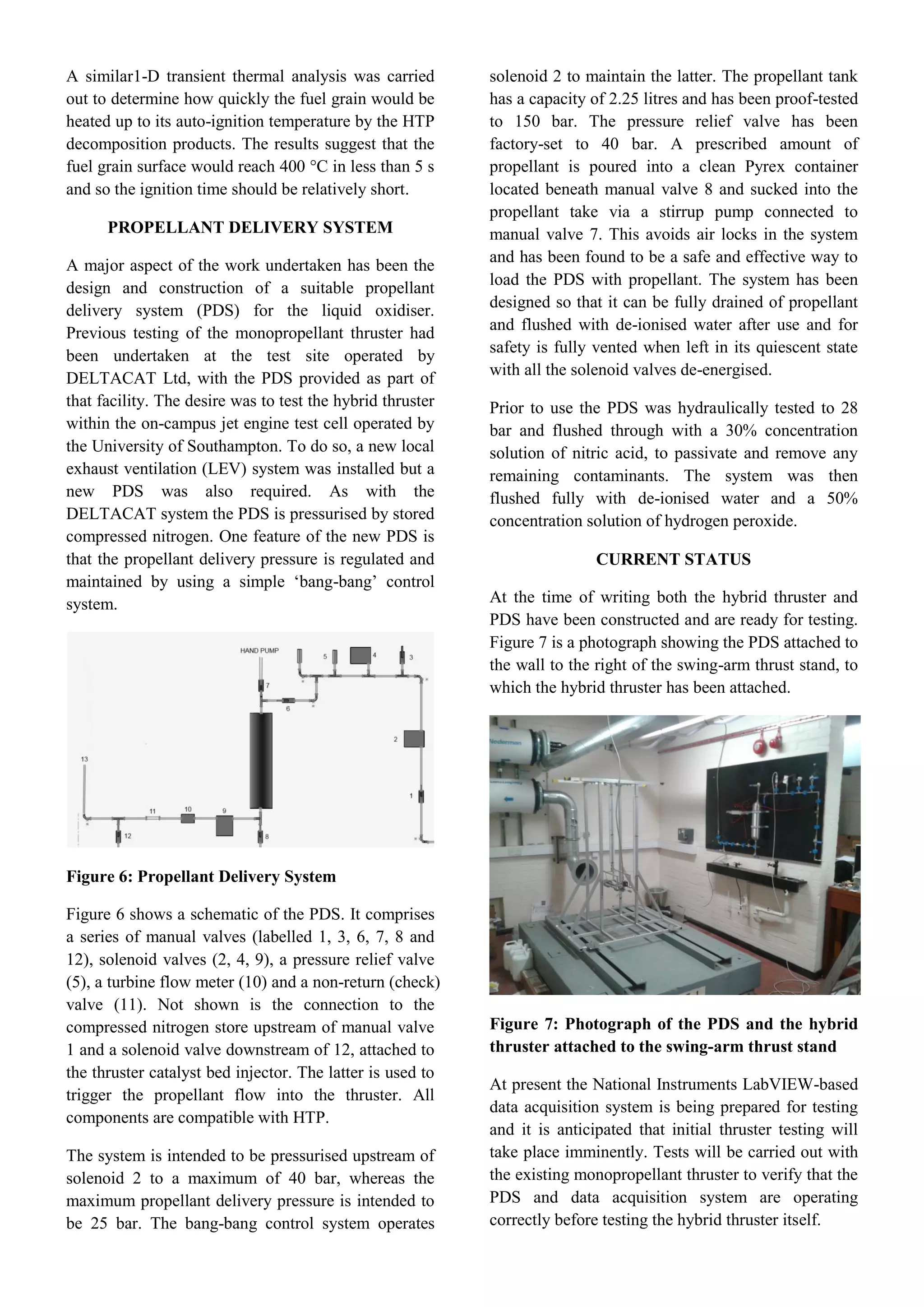
impulse to vary with time.](https://image.slidesharecdn.com/38c56bdb-015d-42c5-b1b8-449b5150c8a3-170224165700/75/Development-of-A-Small-scale-Hybrid-Thruster-Using-Hydrogen-Peroxide-as-the-Oxidiser-SP2014-1-2048.jpg)
![In our current application, we wish to achieve only a
modest thrust level and for the thrust to remain
approximately constant over the burn time. This led
us to select high density polyethylene (HDPE) as the
fuel: it is readily available and relatively cheap
although its regression rate is expected to be lower
than that of LDPE. The auto-ignition temperature of
HDPE (in air) is around 400 °C [7]. Again, for
simplicity in this initial design we have a single
(circular) port configuration for the fuel grain.
Another decision that was taken was to limit the
hybrid burn time to 10s, due to the fact that the
nozzle was to be operated without cooling. The latter
decision was taken to keep the design simple and to
minimise cost. It does, however, mean that we expect
to treat the nozzle as an expendable component that is
likely to experience thermal damage and will
therefore need to be replaced after a few runs. This in
turn meant that the engine had to be modular in
design in order to facilitate replacement of the nozzle
as well as the fuel grain.
Another initial design decision that needed to be
taken was the initial value of the oxidiser:fuel mass
ratio. To facilitate this, the chemical equilibrium code
Cpropep [8] was used. This code is based on the
Chemical Equilibrium with Applications (CEA) code
produced by NASA Glenn Research Centre [9] and
allows the performance of various rocket oxidiser and
fuel combinations to be assessed under given input
conditions. For the present application Cpropep was
run assuming that equilibrium conditions prevail
everywhere and that the combustion takes place at a
pressure of 10 bar with 87.5% HTP/HDPE as the
oxidiser/fuel combination. It is assumed that the
nozzle has been designed for perfect expansion at an
ambient pressure of 1 bar. The effect of varying the
O:F ratio on specific impulse is shown in Fig. 1.
It appears that the peak specific impulse is achieved
at an O:F ratio of approximately 7.5:1 but the
variation is relatively small. Since the fuel regression
rate decreases with time as the combustion port
radius increases, an initial O:F ratio of 6 was chosen,
with the expectation that the option O:F ratio of 7.5
would be achieved about half way through the 10s
run.
Having taken these initial design decisions, a
mathematical model of the thruster design was
constructed, using reference to the literature where
appropriate.
Figure 1: Effect of varying O:F ratio on specific
impulse with H2O2-HDPE
An estimate of the required initial mass flow rate of
fuel to achieve the target initial O:F ratio can be
obtained knowing the oxidiser mass flow rate, and
this is ,f im 3 g/s. This in turn determines the length
of fuel grain required for a given initial port diameter.
This is given by:
,
,2
f i
p i i f
m
L
R r
(1)
where ,f im is the initial fuel mass flow rate, Rp,i is the
initial port radius, ρf is the fuel density and ir is the
initial fuel regression rate. The regression rate is
related to the mass flux of oxidiser (Gox) as follows:
2
n
n ox
ox
p
m
r t aG a
R
(2)
The constant a and the exponent n usually need to be
determined experimentally for a given oxidiser and
fuel combination. The port radius will increase with
time according to:
1
2 1
2 1
,
n n
n ox
p p i
m
R t R a t (3)
The mass flow rate of fuel can be estimated
(assuming the regression is constant along the length
of the fuel grain):
1 2
2
2
f f p
n
nox
f p
m t L rR
m
L a R
(4)
Consequently the regression rate decreases with time,
causing the shift in O:F ratio as noted earlier and is
given by:](https://image.slidesharecdn.com/38c56bdb-015d-42c5-b1b8-449b5150c8a3-170224165700/75/Development-of-A-Small-scale-Hybrid-Thruster-Using-Hydrogen-Peroxide-as-the-Oxidiser-SP2014-2-2048.jpg)
![
1
2 11
2
n
n
ox
p
f
mO
t R t
F a L
(5)
Knowing the O:F ratio from equation (5), the specific
impulse of the engine can be estimated from Fig. 1
and hence the thrust F can be estimated as
0( ) ox f SPF t m m I g (6)
where g0 is the Earth’s gravitational constant. Note
that equation (6) assumes the nozzle flow is perfectly
expanded. From the known oxidiser mass flow rate
and chosen initial O:F ratio equation (6) predicts that
the initial thrust would be approximately 42 N.
As can be seen from equation (4), the O:F shift
depends critically on the values of a and n and, in
particular, if n = 0.5 the shift is zero. For the
propellant combination we are using, workers at the
USAF Academy in Colorado [10] have determined
that 6
7 10
a m3
/kg and n = 0.8 are appropriate.
Because the exponent n is greater than 0.5, according
to equation (4) the O:F ratio will increase with time.
From the above equations it is clear that a critical
design choice is the port initial radius, since this
determines the overall length of fuel grain required,
the regression rate (and hence the required minimum
outer diameter of the fuel grain) and also the O:F
shift. A design spreadsheet incorporating the above
equations was constructed to allow the variation with
port radius to be examined. Some examples of the
output from the spreadsheet are shown in Figs. 2 and
3 below, assuming a hybrid burn time of 10s.
Figure 2 indicates that the regression rate decreases
as the port diameter increases (equations 2 and 3) and
Fig. 3 shows that the change in O:F ratio also
decreases as the port diameter increases (equations 3
and 5). A high regression rate is desirable to
minimise the required length of the fuel grain
(equation 1), favouring a low port radius, but the
consequent shift in O:F ratio would also produce a
shift in the net thrust produced (equations 4 and 6).
Hence a compromise is required. It was decided that
a port radius of 5 mm would result in an acceptable
initial regression rate and the predicted decrease in
thrust over a 10s burn time would be approximately
3%, which was also considered to be acceptable.
Figure 2: Effect of port radius on regression rate
of HDPE with H2O2
Figure 3: Effect of port radius on the O:F ratio
after a 10 s burn with H2O2-HDPE
In summary, we have chosen to operate our hybrid
with HDPE (ρf =950 kg/m3
) as the fuel grain with an
initial port radius of 5mm and at initial O:F ratio of 6;
the predicted initial thrust and specific impulse are
approximately 42 N and 203s respectively and the
required fuel grain length is 186 mm. For a 10 s burn
the increase in port radius is predicted to be
approximately 3.5 mm but to provide a sufficient
factor of safety to prevent burn-through of the fuel
grain, in case our regression rate estimates were
incorrect or (as is quite likely) the regression rate
varies along the length of the fuel grain, an outer
radius of 15 mm was chosen.
THRUSTER DESIGN
As described earlier, the hybrid engine was to be
made modular and had to be compatible with the
existing monopropellant thruster catalyst bed. The
latter had an internal diameter of 21 mm and a mating
flange 50mm in diameter. Figure 4 is a schematic
cross-section of the hybrid section, with parts
labelled 1-8 described below.](https://image.slidesharecdn.com/38c56bdb-015d-42c5-b1b8-449b5150c8a3-170224165700/75/Development-of-A-Small-scale-Hybrid-Thruster-Using-Hydrogen-Peroxide-as-the-Oxidiser-SP2014-3-2048.jpg)
![Figure 4: Hybrid thruster section
Component 1 is the attachment flange section that
connects the hybrid combustion chamber to the
upstream catalyst bed. It is instrumented with a
pressure transducer and also a thermocouple located
on the axis, so that the pressure and temperature
downstream of the catalyst bed can be measured (the
design target values being 10 bar absolute and 600 °C,
respectively). Metal-clad gaskets (item 2 in Fig. 4)
seal the mating surfaces of the combustion chamber
section and the upstream and downstream sections.
The combustion section itself comprises the fuel
grain (6) that is itself encased in a phenolic tube (5)
which slides into the outer casing (4). The outer
casing has mating flanges at either end. At the
upstream end of the combustion chamber an injector
guide ring (3) protects the front face of the fuel grain
from impinging, high temperature oxygen and steam.
Downstream there is a post-combustion chamber (7)
and a nozzle section, with the junction between them
again sealed by a metal-clad gasket (2).
The basic overall dimensions of the combustion
chamber were determined as described in the
previous section. The phenolic tube had an outer
diameter of 32 mm and a wall thickness of 1mm; its
purpose is to provide some degree of thermal
protection for the outer casing should the fuel grain
burn through and also to enable the fuel grain itself to
be removed easily from the outer casing after firing.
The post combustion chamber, also known as the aft
mixing chamber, is intended to ensure that the
combustion process is complete by the time the
combustion products enter the nozzle section. In
effect it provides an extra volume to increase the
characteristic length, L*. The value of L* based on
the initial port volume alone would have been about
0.46 m. Although work carried out by Purdue
University with a similar combination of propellants
indicated that a L* of 0.38 m would be sufficient to
ensure a reasonably high combustion efficiency [11],
we decided to increase the L* to about 1 m (a value
typical for bi-propellant engines [3]) by addition of
the post-combustion chamber, which also acted as a
plenum for the nozzle section. The post-combustion
chamber has a tapping to enable the pressure
downstream of the combustor to be measured.
Since the nozzle section was expected to experience
significant thermal loads, it was designed to be an
expendable item that will need to be replaced after a
few firings. Hence its design was kept relatively
simple, with a 15° half angle conical divergent
section nozzle favoured instead of a contoured profile.
The throat was sized assuming that the initial total
mass flow rate (21 g/s) would be accommodated at a
plenum pressure of 10 bar, with the combustion
products at a temperature of around 2370 °C, as
predicted by Cpropep. This resulted in a throat
diameter of 6.3 mm. The nozzle exit diameter was
determined assuming isentropic and perfectly
expanded flow to ambient pressure (1 bar) and was
9.7 mm (corresponding to an exit Mach number of
approximately 2.2).
Figure 5: Hybrid engine components
A photograph of the hybrid engine components is
shown in Fig. 5. All the materials used had to be
compatible with HTP and its decomposition products.
The upstream attachment flange section and the
combustion chamber outer casing were manufactured
from 316 stainless steel, whereas the post-combustion
chamber and nozzle sections, which experience the
highest thermal loads, were constructed from 321
stainless steel, which has a higher yield and melting
temperature than SS316. A 1-D transient heat transfer
analysis was carried out and suggested that the nozzle
throat surface would remain about 200 °C below the
melting point of the SS321 material (approx..
1500 °C [12]) after a 10 s firing and the post-
combustion chamber surface would reach only about
260 °C in that time.](https://image.slidesharecdn.com/38c56bdb-015d-42c5-b1b8-449b5150c8a3-170224165700/75/Development-of-A-Small-scale-Hybrid-Thruster-Using-Hydrogen-Peroxide-as-the-Oxidiser-SP2014-4-2048.jpg)
![ACKNOWLEDGEMENTS
The authors would like to acknowledge the financial
support of Surrey Satellites Technology Ltd (SSTL)
and also to thank Matt Palmer of SSTL for technical
advice concerning the thruster instrumentation and
data acquisition system. We would also like to
acknowledge the help of the technical staff at the
University in various aspects of this work.
REFERENCES
[1] M.J. Palmer, G.T. Roberts and A.J. Musker
“Design, Build and Test of a 20N Hydrogen Peroxide
Monopropellant Thruster” AIAA paper 2011-5697
presented at 47th
Joint Propulsion Conference, San
Diego, July-Aug 2011.
[2] A.J. Musker “Development of a 200 Newton Bi-
propellant Thruster Using Heterogeneous Catalytic
Reduction of Hydrogen Peroxide” presented at 4th
European Congress of aerospace Sciences
(EUCASS), St. Petersburg, Russia, July 2011.
[3] G.P. Sutton and O.Biblarz “Rocket Propulsion
Elements” 8th
ed. Wiley, 2010. ISBN 978-0-470-
08024-5.
[4] T. Brown and M. Lydon “Testing of Paraffin-
Based Hybrid Rocket Fuel Using Hydrogen Peroxide
Oxidiser, US Air Force Academy report, 2005,
accessed 27/04/2014 via
http://spacegrant.colorado.edu/COSGC_Projects/sym
posium_archive/2005/docs/115.pdf
[5] E. Farbar, J. Louwers, and T.
Kaya. "Investigation of Metallized and
Nonmetallized Hydroxyl Terminated
Polybutadiene/Hydrogen Peroxide Hybrid
Rockets", Journal of Propulsion and Power, Vol.
23, No. 2 (2007), pp. 476-486.
[6] J.Tsohasi, B. Appel, A. Rettenmaier, M. Walker
and S. Heister “Development and Launch of the
Purdue Hybrid Rocket Technology Demonstrator”,
AIAA paper 2009-4842 presented at the 45th
Joint
Propulsion Conference, Denver, Aug. 2009.
[7]
http://www.jgspetrochem.com/Evalene%20Polyethyl
ene%20-%20MSDS.pdf Last accessed 27/04/2014.
[8] Cpropep available for download from
http://rocketworkbench.sourceforge.net/projects.phtm
l Last accessed 27/04/14.
[9] S. Gordon, B.J. McBride “Computer Program for
Calculation of Complex Chemical Equilibrium
Compositions and Applications” NASA RP-1311,
1994.
See also:
http://www.grc.nasa.gov/WWW/CEAWeb/ceaHome.
htm last accessed 27/04/2014.
[10] M.Bettner, R. Humble “Polyethylene and
Hydrogen Peroxide Testing at the USAF Academy”
presented at the 1st
Hydrogen Peroxide Conference,
University of Surrey, UK, 1998. Accessed 27/04/14
via http://www.dtic.mil/docs/citations/ADA367246
[11]E. Wernimont and S. Heister “Combustion
Experiments in Hydrogen Peroxide/Polyethylene
Hybrid Rockets with Catalytic Ignition” J. Propulsion
and Power, 2000, 16(2), 323-324.
[12] Altemp Alloys, 321 Stainless Steel,
http://www.altempalloys.com/321-stainless.html last
accessed 27/04/14.](https://image.slidesharecdn.com/38c56bdb-015d-42c5-b1b8-449b5150c8a3-170224165700/75/Development-of-A-Small-scale-Hybrid-Thruster-Using-Hydrogen-Peroxide-as-the-Oxidiser-SP2014-6-2048.jpg)


