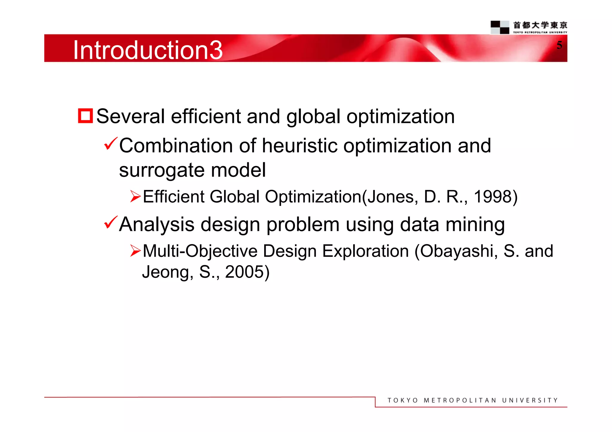
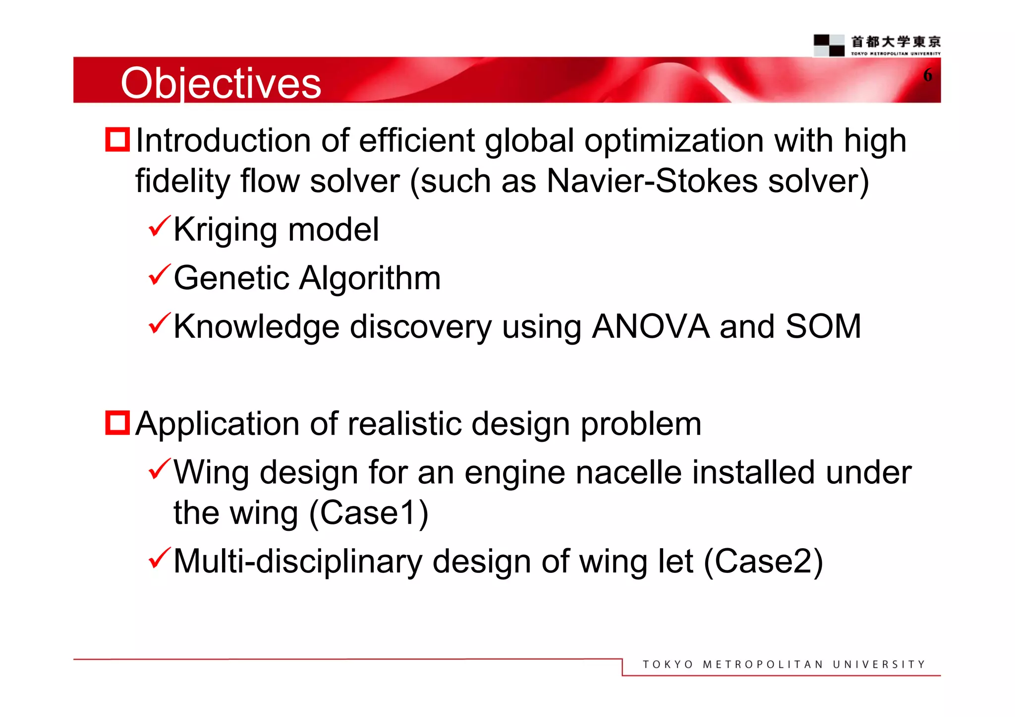
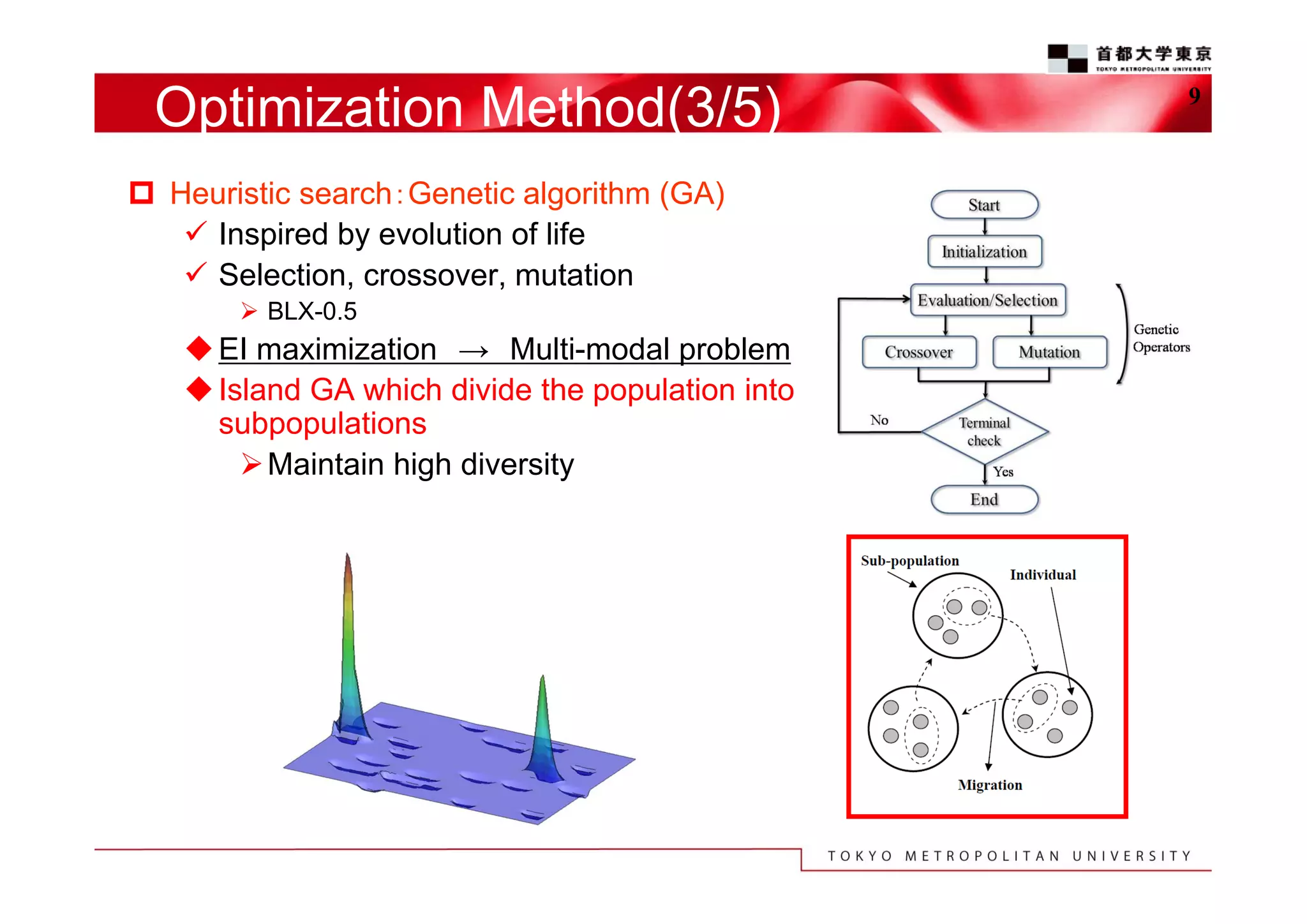
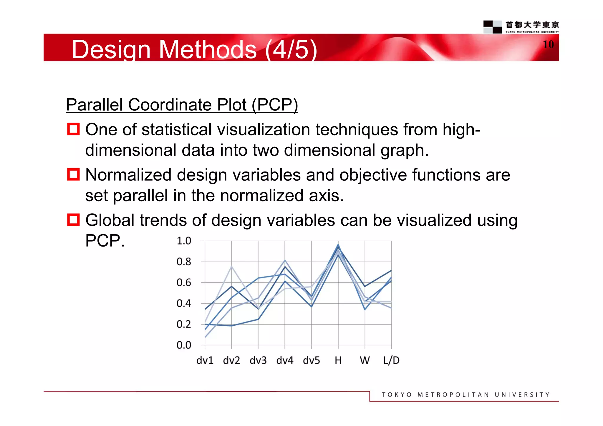
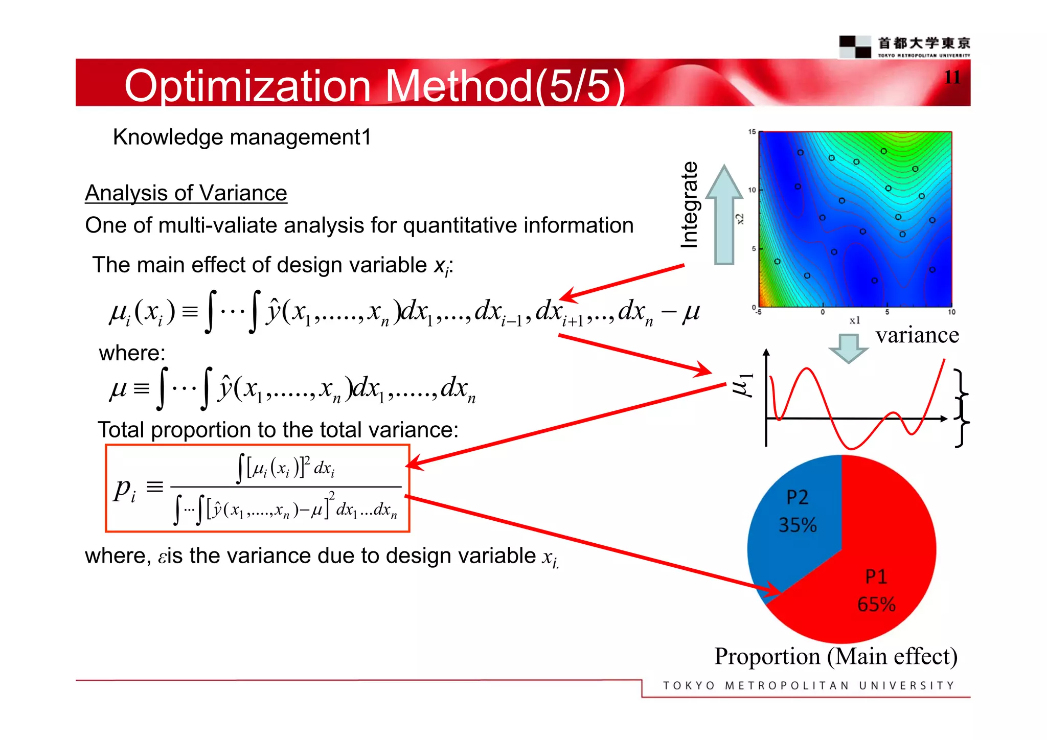
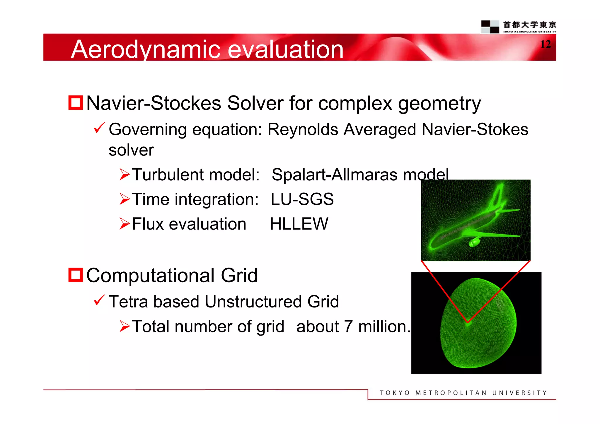
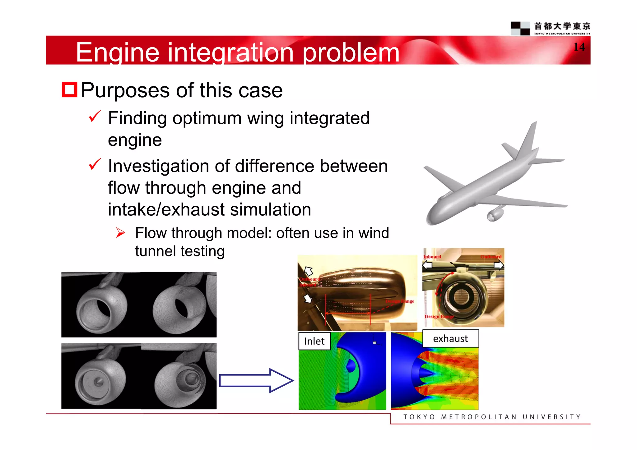
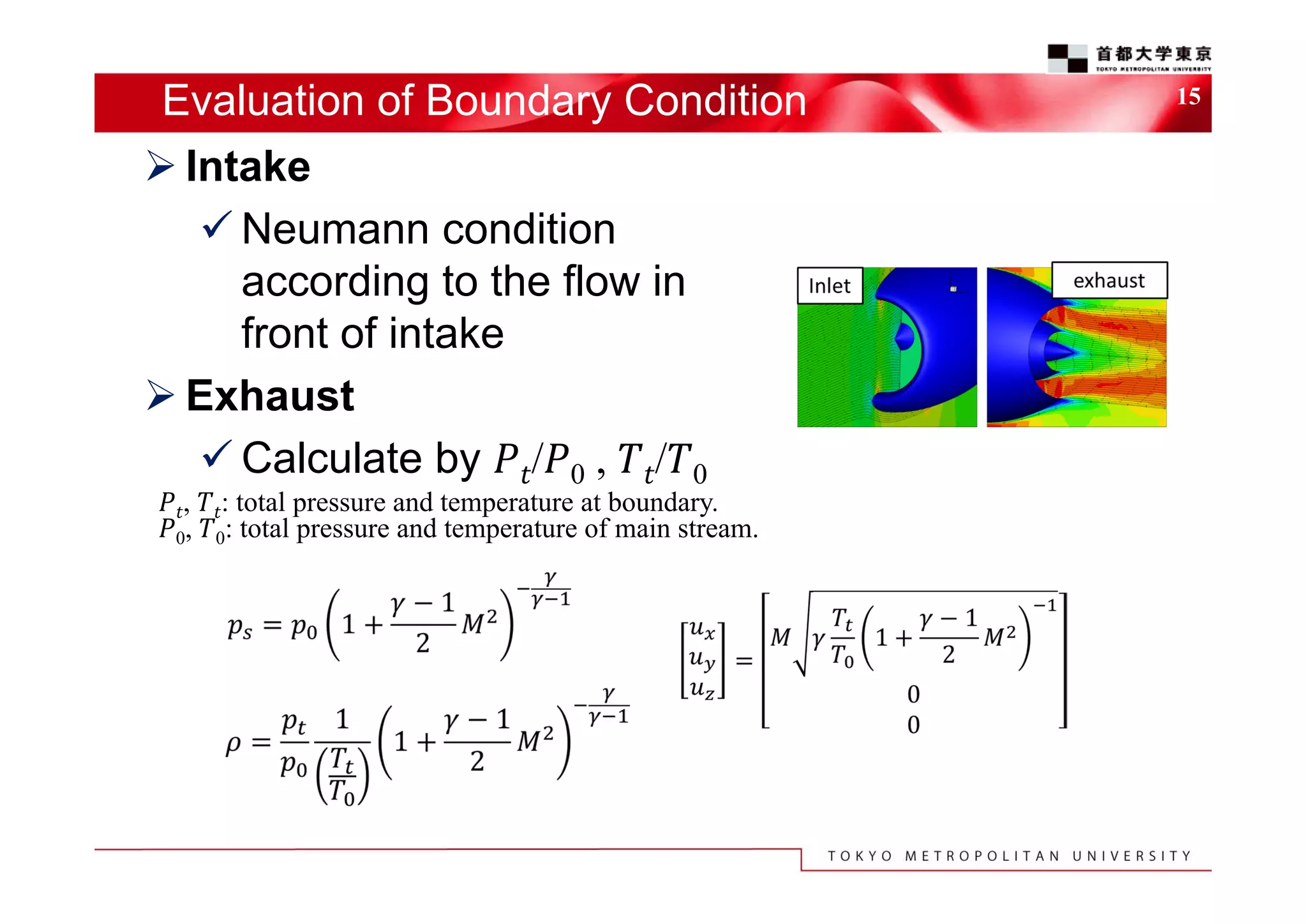
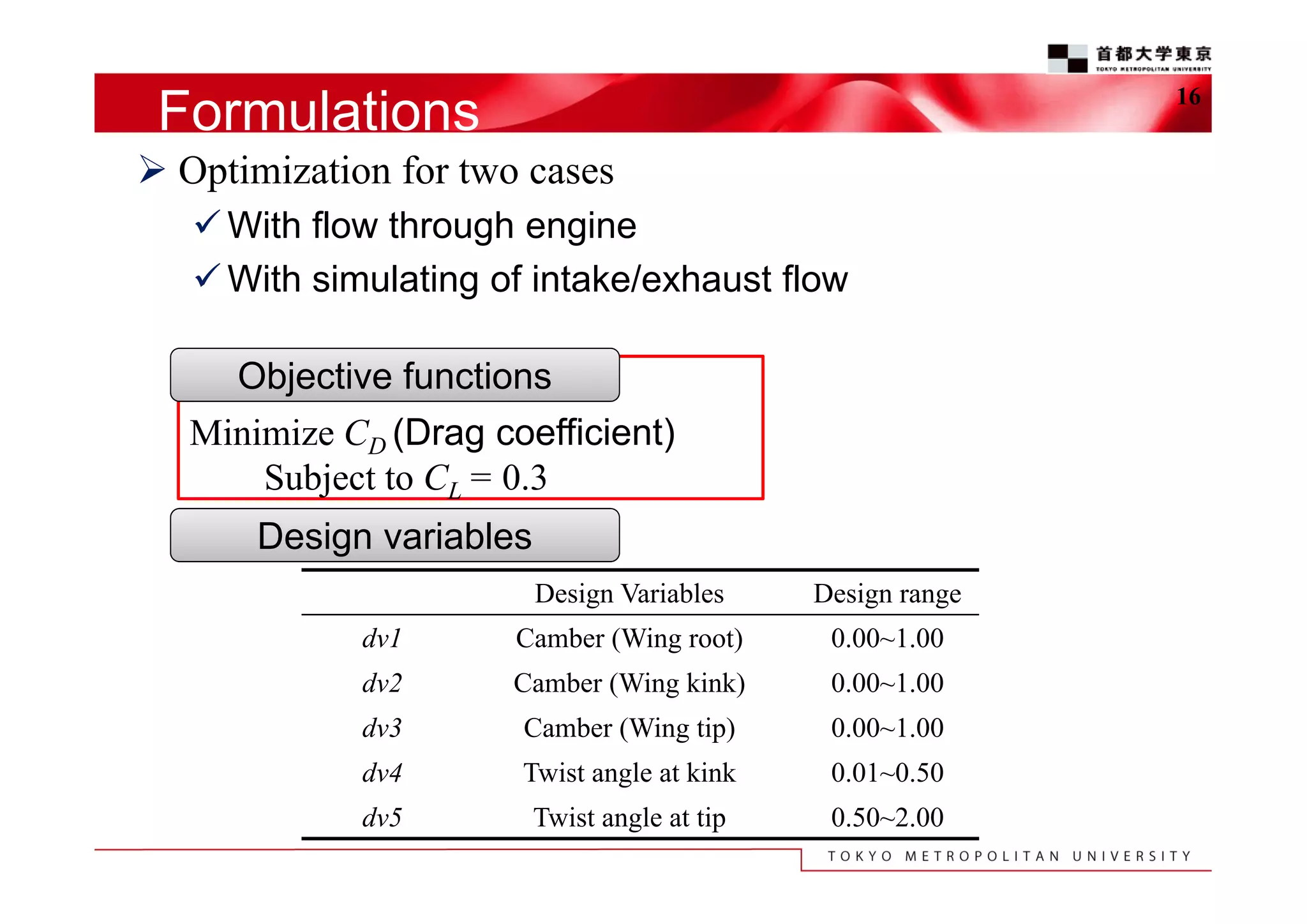
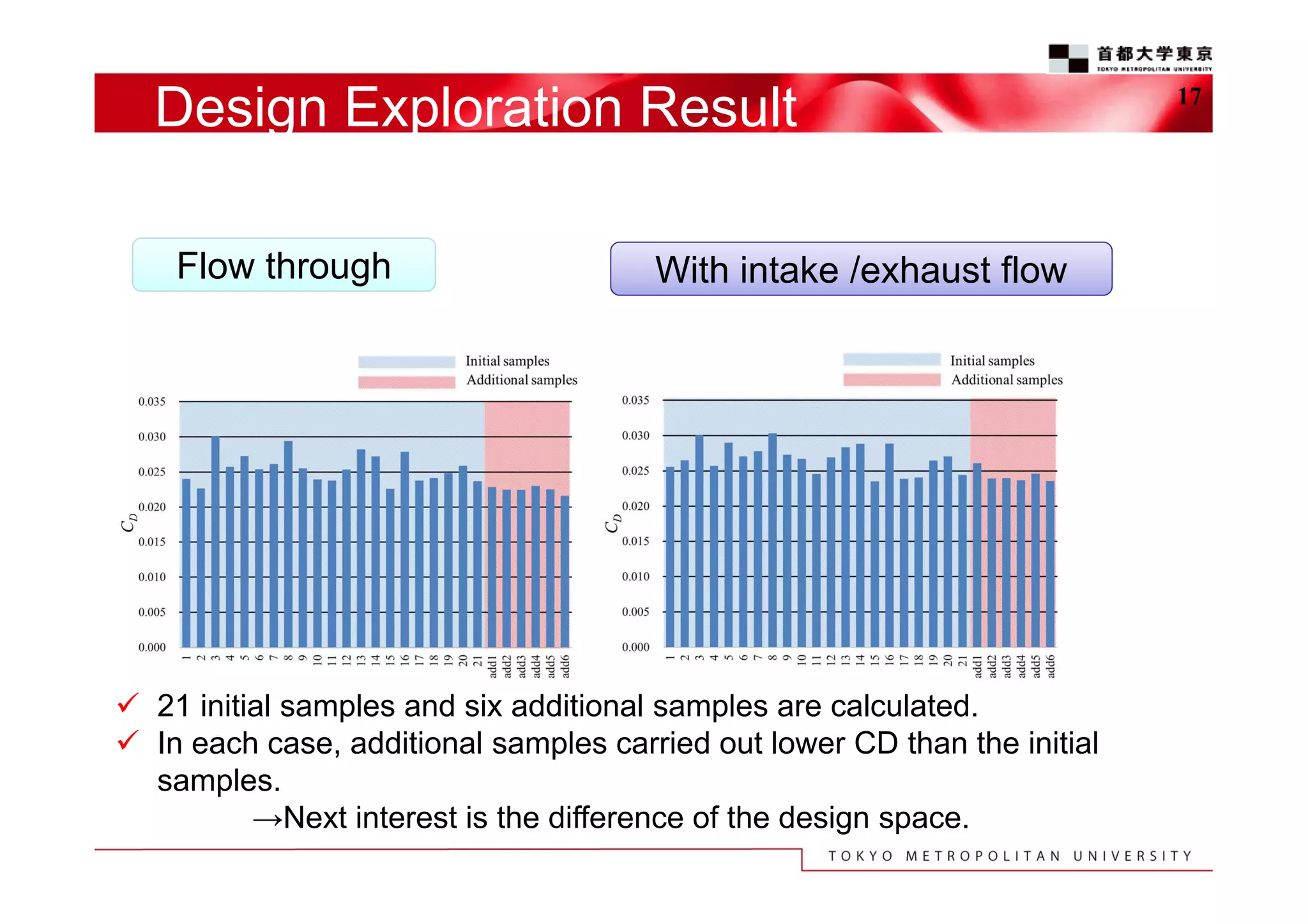
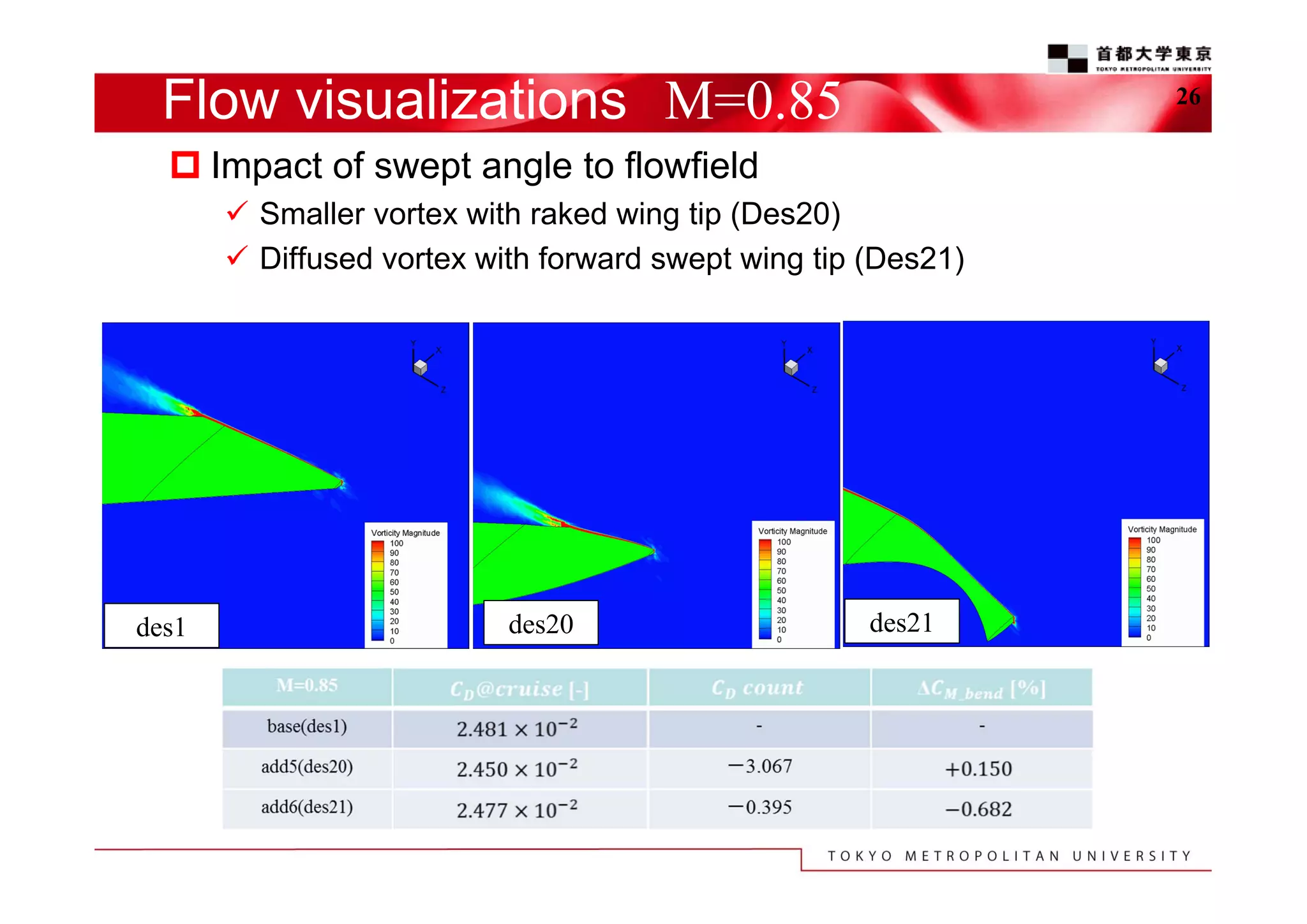
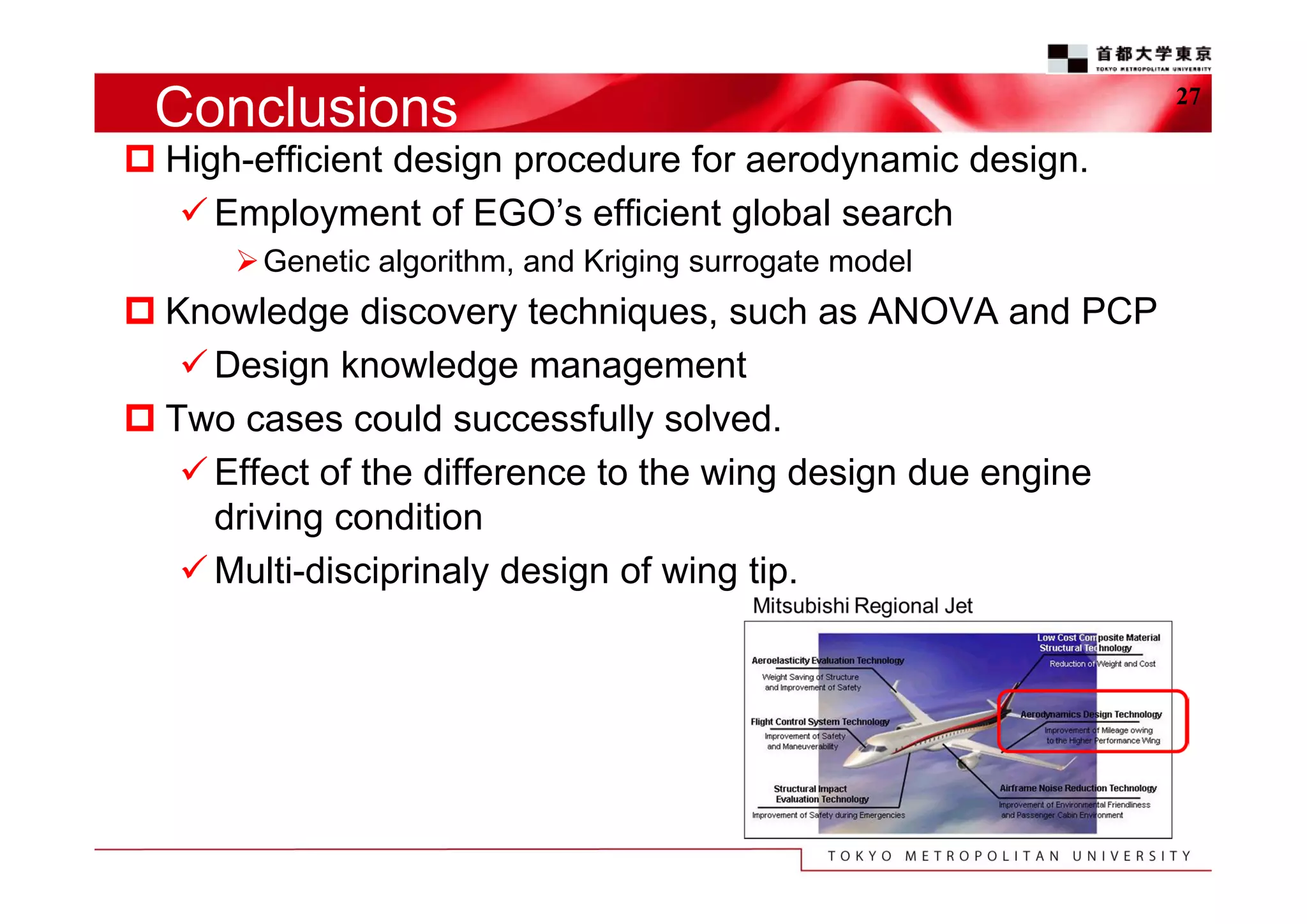
The document discusses the efficient design exploration for civil aircraft using a kriging-based genetic algorithm. It presents two case studies focused on optimizing the aerodynamic design of a wing integrated engine nacelle and multi-disciplinary design of wing tips, employing efficient global optimization methods. The findings emphasize the significance of design variables affecting drag and the importance of integrating knowledge discovery techniques for enhancing design processes.
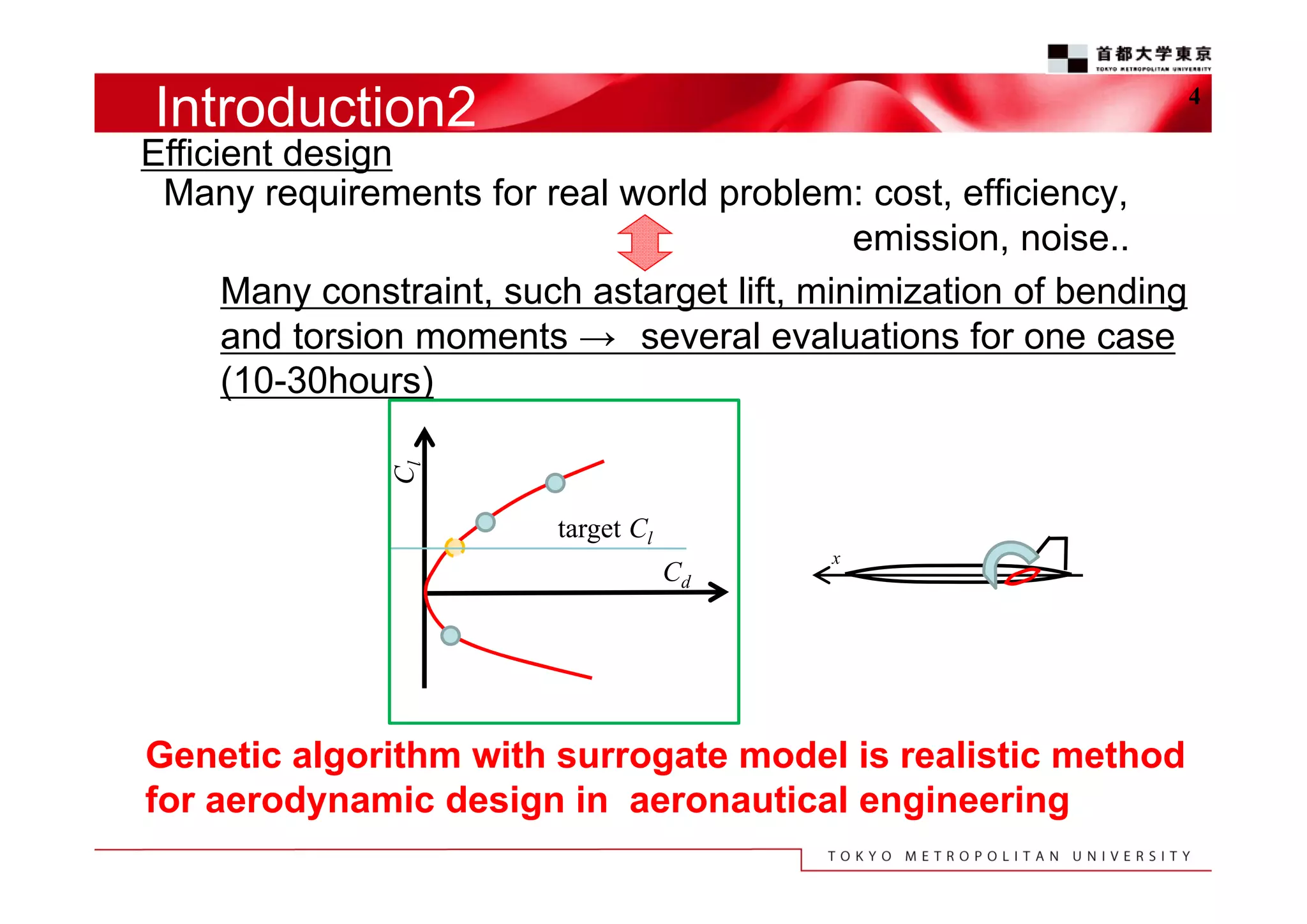
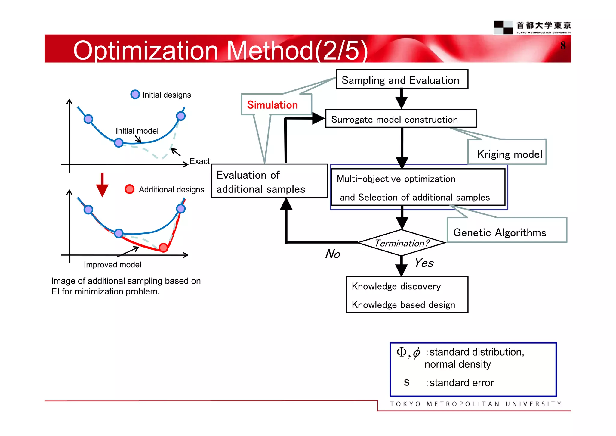
![Optimization Method(1/5)
7
Surrogate model:Kriging model
Interpolation based on sampling data
Standard error estimation (uncertainty)
y (xi ) (xi )
global model
localized deviation
from the global model
EI(Expected Improvement)
The balance between optimality and uncertainty
EI maximum point has possibility to improve the model.
Improvement at a point x is
I=max(fmin-Y,0)
Expected improvement E[I(x))]=E[max(fmin-Y,0)]
To calculate EI,
Jones, D. R., “Efficient Global
Optimization of Expensive BlackBox Functions,” J. Glob. Opt., Vol.
13, pp.455-492 1998.](https://image.slidesharecdn.com/131009ms6beurogen2013-131103224549-phpapp01/75/Efficient-Design-Exploration-for-Civil-Aircraft-Using-a-Kriging-Based-Genetic-Algorithm-7-2048.jpg)


![Soundtoys Mac v5.5.5.0 Crack for MacOS Full Version [Latest] pptx](https://cdn.slidesharecdn.com/ss_thumbnails/softwareoverview-251207193711-91d8ae6b-thumbnail.jpg?width=640&height=640&fit=bounds)
![AnyTrans for iOS 8.9.14.20251127 With Crack for MacOS [Latest] pptx](https://cdn.slidesharecdn.com/ss_thumbnails/softwareoverview-251207190907-2316965f-thumbnail.jpg?width=640&height=640&fit=bounds)


![Driver Easy Pro Key 7.1.0.2641 Full Mac Crack Free Activated Download [2026]....](https://cdn.slidesharecdn.com/ss_thumbnails/software-251207185324-b2fb71b4-thumbnail.jpg?width=640&height=640&fit=bounds)

![Wondershare Filmora 15.0.11 Crack for Mac Key Full Download [Latest] pptx](https://cdn.slidesharecdn.com/ss_thumbnails/software-251207184836-1d16ba16-thumbnail.jpg?width=640&height=640&fit=bounds)
![WinRAR Crack 7.13 Final Mac Keygen 2026 Download [Latest] Software.pptx](https://cdn.slidesharecdn.com/ss_thumbnails/software-251207185858-eb450678-thumbnail.jpg?width=640&height=640&fit=bounds)


