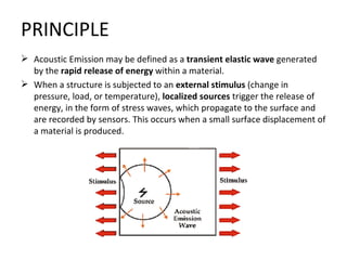
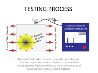
Acoustic Emission (AE) refers to the generation of transient elastic waves produced by a sudden redistribution of stress in a material. When a structure is subjected to an external stimulus (change in pressure, load, or temperature), localized sources trigger the release of energy, in the form of stress waves, which propagate to the surface and are recorded by sensors. With the right equipment and setup, motions on the order of picometers (10 -12 m) can be identified. Sources of AE vary from natural events like earthquakes and rockbursts to the initiation and growth of cracks, slip and dislocation movements, melting, twinning, and phase transformations in metals. In composites, matrix cracking and fiber breakage and debonding contribute to acoustic emissions. AE’s have also been measured and recorded in polymers, wood, and concrete, among other materials.
NON DESTRUCTIVE TESTING TECHNIQUES ARE USEFUL FOR FINDING DEFECTS LIKE CRACKS,POROSITY,FLAWS,BLOWHOLES IN MATERIALS WITHOUT DESTRUCTING COMPONENT. IT IS ALSO USEFUL FOR TAKING DECISIONS RELATED TO QUALITY OF MATERIAL OR PRODUCT. Non destructive testing includes study and testing of components by various methods such as dye penetration test, eddy current test, magnetic particle test, ndt, radiography test, ultrasonic test.
Introduction to NDT and Visual Inspection Hareesh K
This presentation will gives you basic idea about Non destructive testing and brief detail about Visual Inspection Technique.This topic is included in UG level Mechanical Engineering Syllabus by all top Indian Universities
This presentation gives the information about 'vibration measuring instruments' covering syllabus of Unit-5 of Theory of vibrations or mechanical vibrations for BE course under VTU, Belgaum. This presentation is prepared by Hareesha N G, Asst. Prof, Dept of Aerospace, DSCE, B'Lore-78.
International Journal of Engineering Research and Development (IJERD)IJERD Editor
call for paper 2012, hard copy of journal, research paper publishing, where to publish research paper,
journal publishing, how to publish research paper, Call For research paper, international journal, publishing a paper, IJERD, journal of science and technology, how to get a research paper published, publishing a paper, publishing of journal, publishing of research paper, reserach and review articles, IJERD Journal, How to publish your research paper, publish research paper, open access engineering journal, Engineering journal, Mathemetics journal, Physics journal, Chemistry journal, Computer Engineering, Computer Science journal, how to submit your paper, peer reviw journal, indexed journal, reserach and review articles, engineering journal, www.ijerd.com, research journals,
yahoo journals, bing journals, International Journal of Engineering Research and Development, google journals, hard copy of journal
Final strip and sheet steel product is commonly inspected with great scrutiny to qualify material for high-end product requirements. Surface flaws such as slivers, cracks, laps, etc., disqualify these materials from being used in automotive and big box applications. Internal defects such as voids, cracks, laminations, porosity and segregation may remain undetectable with surface inspection methods as they have not yet manifested at the surface. These internal defects often propagate to the surface where ultimately they are detectable in the finished product stage in the form of slivers, blisters, etc., although remaining undetectable in the steel making, hot-rolling, pickling, cold rolling and subsequent finishing operations. Surface flaws are a key cause of down grading of finished product and a significant cost to the steel maker as all value added operations are complete before detection and down grading are possible.
In today’s competitive environment, it is key to maximize utilization of mill assets and to avoid adding value to material which can be known early in the manufacturing process to contain deleterious defects. Using proven methods of volumetric material inspection in two separate case studies, methods have been developed to allow the steel maker to identify poor material early in the process thus avoiding the value added processes on these materials and only processing materials which with a probability of final inspection passage.
While research and development of Electro-Magnetic Acoustic Transducer (EMAT) technology has been active for several decades, hardened production inspection system applications remain limited. Applications remain limited despite the several and distinct advantages and EMAT probe can have over conventional piezoelectric ultrasonic devices.
In addition to being comparable in ultrasonic wave mode generation and sensitivity, under proper design, an EMAT probe offers the following advantages for the production minded engineer: (1) no fluid couplant is required, (2) the test can be non-contact, (3) works on rough, dirty, and hot surfaces, (4) can be operated at very high scan rates, (5) easy to automate, and (6) capable of generating useful waves modes that are difficult to generate with piezoelectric devices. Basic elements of an EMAT system are explained and a comparison to conventional piezoelectric devices is made. By using real application cases, the benefits of EMATs are demonstrated. These real cases include: (1) flash butt-weld inspection, (2) mill roll inspection, (3) automotive laser weld inspection, and (4) tube & pipe inspection.
This paper reviews major research developments over the past few years in application of acoustic emission in numerous engineering fields, including manufacturing, civil, aerospace and material engineering.
Smart Sound Processing for Defect Sizing in Pipelines Using EMAT Actuator Bas...Innerspec Technologies
Pipeline inspection is a topic of particular interest to the companies. Especially important is the defect sizing, which allows them to avoid subsequent costly repairs in their equipment. A solution for this issue is using ultrasonic waves sensed through Electro-Magnetic Acoustic Transducer (EMAT)
actuators. The main advantage of this technology is the absence of the need to have direct contact with the surface of the material under investigation, which must be a conductive one. Specifically interesting is the meander-line-coil based Lamb wave generation, since the directivity of the waves allows a study based in the circumferential wrap-around received signal. However, the variety of defect sizes changes the behavior of the signal when it passes through the pipeline. Because of that, it is necessary to apply advanced techniques based on Smart Sound Processing (SSP). These methods involve extracting useful information from the signals sensed with EMAT at different frequencies to obtain nonlinear estimations of the depth of the defect, and to select the features that better estimate the profile of the pipeline. The proposed technique has been tested using both simulated and real signals in steel pipelines, obtaining good results in terms of Root Mean Square Error (RMSE).
UiPath Test Automation using UiPath Test Suite series, part 3DianaGray10
Welcome to UiPath Test Automation using UiPath Test Suite series part 3. In this session, we will cover desktop automation along with UI automation.
Topics covered:
UI automation Introduction,
UI automation Sample
Desktop automation flow
Pradeep Chinnala, Senior Consultant Automation Developer @WonderBotz and UiPath MVP
Deepak Rai, Automation Practice Lead, Boundaryless Group and UiPath MVP
The Art of the Pitch: WordPress Relationships and SalesLaura Byrne
Clients don’t know what they don’t know. What web solutions are right for them? How does WordPress come into the picture? How do you make sure you understand scope and timeline? What do you do if sometime changes?
All these questions and more will be explored as we talk about matching clients’ needs with what your agency offers without pulling teeth or pulling your hair out. Practical tips, and strategies for successful relationship building that leads to closing the deal.
Smart TV Buyer Insights Survey 2024 by 91mobiles.pdf91mobiles
91mobiles recently conducted a Smart TV Buyer Insights Survey in which we asked over 3,000 respondents about the TV they own, aspects they look at on a new TV, and their TV buying preferences.
Key Trends Shaping the Future of Infrastructure.pdfCheryl Hung
Keynote at DIGIT West Expo, Glasgow on 29 May 2024.
Cheryl Hung, ochery.com
Sr Director, Infrastructure Ecosystem, Arm.
The key trends across hardware, cloud and open-source; exploring how these areas are likely to mature and develop over the short and long-term, and then considering how organisations can position themselves to adapt and thrive.
Essentials of Automations: Optimizing FME Workflows with ParametersSafe Software
Are you looking to streamline your workflows and boost your projects’ efficiency? Do you find yourself searching for ways to add flexibility and control over your FME workflows? If so, you’re in the right place.
Join us for an insightful dive into the world of FME parameters, a critical element in optimizing workflow efficiency. This webinar marks the beginning of our three-part “Essentials of Automation” series. This first webinar is designed to equip you with the knowledge and skills to utilize parameters effectively: enhancing the flexibility, maintainability, and user control of your FME projects.
Here’s what you’ll gain:
- Essentials of FME Parameters: Understand the pivotal role of parameters, including Reader/Writer, Transformer, User, and FME Flow categories. Discover how they are the key to unlocking automation and optimization within your workflows.
- Practical Applications in FME Form: Delve into key user parameter types including choice, connections, and file URLs. Allow users to control how a workflow runs, making your workflows more reusable. Learn to import values and deliver the best user experience for your workflows while enhancing accuracy.
- Optimization Strategies in FME Flow: Explore the creation and strategic deployment of parameters in FME Flow, including the use of deployment and geometry parameters, to maximize workflow efficiency.
- Pro Tips for Success: Gain insights on parameterizing connections and leveraging new features like Conditional Visibility for clarity and simplicity.
We’ll wrap up with a glimpse into future webinars, followed by a Q&A session to address your specific questions surrounding this topic.
Don’t miss this opportunity to elevate your FME expertise and drive your projects to new heights of efficiency.
LF Energy Webinar: Electrical Grid Modelling and Simulation Through PowSyBl -...DanBrown980551
Do you want to learn how to model and simulate an electrical network from scratch in under an hour?
Then welcome to this PowSyBl workshop, hosted by Rte, the French Transmission System Operator (TSO)!
During the webinar, you will discover the PowSyBl ecosystem as well as handle and study an electrical network through an interactive Python notebook.
PowSyBl is an open source project hosted by LF Energy, which offers a comprehensive set of features for electrical grid modelling and simulation. Among other advanced features, PowSyBl provides:
- A fully editable and extendable library for grid component modelling;
- Visualization tools to display your network;
- Grid simulation tools, such as power flows, security analyses (with or without remedial actions) and sensitivity analyses;
The framework is mostly written in Java, with a Python binding so that Python developers can access PowSyBl functionalities as well.
What you will learn during the webinar:
- For beginners: discover PowSyBl's functionalities through a quick general presentation and the notebook, without needing any expert coding skills;
- For advanced developers: master the skills to efficiently apply PowSyBl functionalities to your real-world scenarios.
Software Delivery At the Speed of AI: Inflectra Invests In AI-Powered QualityInflectra
In this insightful webinar, Inflectra explores how artificial intelligence (AI) is transforming software development and testing. Discover how AI-powered tools are revolutionizing every stage of the software development lifecycle (SDLC), from design and prototyping to testing, deployment, and monitoring.
Learn about:
• The Future of Testing: How AI is shifting testing towards verification, analysis, and higher-level skills, while reducing repetitive tasks.
• Test Automation: How AI-powered test case generation, optimization, and self-healing tests are making testing more efficient and effective.
• Visual Testing: Explore the emerging capabilities of AI in visual testing and how it's set to revolutionize UI verification.
• Inflectra's AI Solutions: See demonstrations of Inflectra's cutting-edge AI tools like the ChatGPT plugin and Azure Open AI platform, designed to streamline your testing process.
Whether you're a developer, tester, or QA professional, this webinar will give you valuable insights into how AI is shaping the future of software delivery.
Generating a custom Ruby SDK for your web service or Rails API using Smithyg2nightmarescribd
Have you ever wanted a Ruby client API to communicate with your web service? Smithy is a protocol-agnostic language for defining services and SDKs. Smithy Ruby is an implementation of Smithy that generates a Ruby SDK using a Smithy model. In this talk, we will explore Smithy and Smithy Ruby to learn how to generate custom feature-rich SDKs that can communicate with any web service, such as a Rails JSON API.
UiPath Test Automation using UiPath Test Suite series, part 4DianaGray10
Welcome to UiPath Test Automation using UiPath Test Suite series part 4. In this session, we will cover Test Manager overview along with SAP heatmap.
The UiPath Test Manager overview with SAP heatmap webinar offers a concise yet comprehensive exploration of the role of a Test Manager within SAP environments, coupled with the utilization of heatmaps for effective testing strategies.
Participants will gain insights into the responsibilities, challenges, and best practices associated with test management in SAP projects. Additionally, the webinar delves into the significance of heatmaps as a visual aid for identifying testing priorities, areas of risk, and resource allocation within SAP landscapes. Through this session, attendees can expect to enhance their understanding of test management principles while learning practical approaches to optimize testing processes in SAP environments using heatmap visualization techniques
What will you get from this session?
1. Insights into SAP testing best practices
2. Heatmap utilization for testing
3. Optimization of testing processes
4. Demo
Topics covered:
Execution from the test manager
Orchestrator execution result
Defect reporting
SAP heatmap example with demo
Speaker:
Deepak Rai, Automation Practice Lead, Boundaryless Group and UiPath MVP
2. PRINCIPLE
Acoustic Emission may be defined as a transient elastic wave generated
by the rapid release of energy within a material.
When a structure is subjected to an external stimulus (change in
pressure, load, or temperature), localized sources trigger the release of
energy, in the form of stress waves, which propagate to the surface and
are recorded by sensors. This occurs when a small surface displacement of
a material is produced.
3. HISTORY & FACTS
Probably the first practical use of AE was by pottery makers. As early as
6,500 BC, potters were known to listen for audible sounds during the
cooling of their ceramics, to asses the quality of there products.
Probably the first observation of AE in metal was during twinning of pure
tin as early as 3700 B.C.
The first documented observations of AE appear to have been made in the
8th century by Arabian alchemist Jabir ibn Hayyan. He described the
“harsh sound or crashing noise” emitted from tin. He also describes iron as
“sounding much” during forging.
In 1936, Friedrich Forster and Erich Scheil (Germany) conducted
experiments that measured small voltage and resistance variations caused
by sudden strain movements caused by martensitic transformations.
Today, AE Non-Destructive Testing used practically in all industries around
the world for different types of structures and materials.
4. TESTING PROCESS
Materials "talk" when they are in trouble: with Acoustic
Emission equipment you can "listen" to the sounds of
cracks growing, fibers breaking and many other modes of
active damage in the stressed material.
5. 1. DETECTION OF AE
Sources of AE include many
different mechanisms of
deformations and fracture whilst
the detection process remains the
same.
As a crack grows a number of
emissions are released.
When the AE wave front arrives at
the surface of a test specimen
minute movements of the surface
molecules occur.
The function of AE sensors is to
detect this mechanical movement
and convert it into a useable
electric signal.
6. 2. PROCESSING OF AE
SIGNALS
The small voltage generated by the
sensor is amplified and the raw
radio frequency (RF) signal is
transferred to the computer.
Based on user defined
characteristics, the RF signal is split
into discrete waveforms.
These waveforms are then
prescribed by characteristics such
as amplitude, rise time, absolute
energy based on a user defined
threshold.
7. 3. DISPLAYING AE
SIGNALS
The collected waveforms can then
be displayed in two ways.
One, function of waveform
parameters.
Two, as the collected waveform
itself.
Most AE tests currently only record
the waveform parameters and
ignore the collected waveform,
mainly due to the large amount of
computing memory it uses.
8. 4. LOCATING AE
SIGNALS
The automated source location
capability of AE is perhaps its most
significant attraction as a non-
destructive testing (NDT)
technique.
The predominant method of source
location is based on the
measurement of time difference
between the arrival of individual AE
signals at different sensors in an
array.
9. DIFFERENT FROM OTHER NDT
TECHNIQUES
The first difference pertains to the origin of the signal. Instead of
supplying energy to the object under examination, AET simply listens for
the energy released by the object. AE tests are often performed on
structures while in operation, as this provides adequate loading for
propagating defects and triggering acoustic emissions.
The second difference is that AET deals with dynamic processes, or
changes, in a material. This is particularly meaningful because only active
features (e.g. crack growth) are highlighted. The ability to discern
between developing and stagnant defects is significant. However, it is
possible for flaws to go undetected altogether if the loading is not high
enough to cause an acoustic event. Furthermore, AE testing usually
provides an immediate indication relating to the strength or risk of failure
of a component. Other advantages of AET include fast and complete
volumetric inspection using multiple sensors, permanent sensor
mounting for process control, and no need to disassemble and clean a
specimen.
10. AE SOURCE LOCATION
TECHNIQUES
Locating the source
of significant
acoustic emissions is
often the main goal
of an inspection.
11. 1. MULTIPLE CHANNEL SOURCE
LOCATION TECHNIQUE
AE systems are capable of using multiple
sensors/channels during testing,
allowing them to record a hit from a
single AE event.
As hits are recorded by each
sensor/channel, the source can be
located by knowing the velocity of the
wave in the material and the difference
in hit arrival times among the sensors, as
measured by hardware circuitry or
computer software.
Source location techniques assume that
AE waves travel at a constant velocity in
a material. By properly spacing the
sensors in this manner, it is possible to
inspect an entire structure with
relatively few sensors.
12. 2. LINEAR LOCATION
TECHNIQUE
One of the commonly used
computed-source location
techniques is the linear location
principle
Linear location is often used to
evaluate struts on truss bridges.
When the source is located at the
midpoint, the time of arrival
difference for the wave at the two
sensors is zero.
Whether the location lies to the
right or left of the midpoint is
determined by which sensor first
records the hit. This is a linear
relationship and applies to any
event sources between the sensors.
13. 3. ZONAL LOCATION
TECHNIQUE
As the name implies, zonal location
aims to trace the waves to a specific
zone or region around a sensor.
Zones can be lengths, areas or volumes
depending on the dimensions of the
array.
The source can be assumed to be within
the region and less than halfway
between sensors.
When additional sensors are applied,
arrival times and amplitudes help
pinpoint the source zone.
14. 4. POINT LOCATION
In order for point location to be
justified, signals must be detected in a
minimum number of sensors: two for
linear, three for planar, four for
volumetric.
Accurate arrival times must also be
available.
The velocity of wave propagation and
exact position of the sensors are the
necessary criteria.
Equations can then be derived using
sensor array geometry or more complex
algebra to locate more specific points of
interest.
15. INSTRUMENTATION
Typical AE apparatus consist of the following
components:
Sensors used to detect AE events.
Preamplifiers amplifies initial signal. Typical
amplification gain is 40 or 60 dB.
Cables transfer signals on distances up to 200m to
AE devices. Cables are typically of coaxial type.
Data acquisition device performs filtration, signals’
parameters evaluation, data analysis and charting.
16. SENSOR
AE sensors respond with amazing
sensitivity to motion in the low
ultrasonic frequency range (10 kHz -
2000 kHz). Motions as small as 10-12
inches and less can be detected.
These sensors can hear the
breaking of a single grain in a metal,
a single fiber in a fiber-reinforced
composite, and a tiny gas bubble
from a pinhole leak as it arrives at
the liquid surface.
The transducer element in an AE
sensor is almost always a
piezoelectric crystal, which is
commonly made from a ceramic
such as lead zirconate titanate
(PZT).
17. APPLICATIONS
1. WELD MONITORING
During the welding process,
temperature changes induce
stresses between the weld and
the base metal.
These stresses are often
relieved by heat treating the
weld.
18. 2. BUCKET TRUCK
INTEGRITY
EVALUATION
Accidents, overloads and
fatigue can all occur when
operating bucket trucks or
other aerial equipment.
If a mechanical or structural
defect is ignored, serious
injury or fatality can result.
19. 3. BRIDGES
Bridges contain many welds, joints
and connections, and a combination
of load and environmental factors
heavily influence damage
mechanisms such as fatigue cracking
and metal thinning due to corrosion.
Acoustic Emission is increasingly being
used for bridge monitoring
applications because it can
continuously gather data and detect
changes that may be due to damage
without requiring lane closures or
bridge shutdown.
In fact, traffic flow is commonly used
to load or stress the bridge for the AE
testing.
20. 4. AEROSPACE
STRUCTURES
Most aerospace structures consist
of complex assemblies of
components that have been design
to carry significant loads while
being as light as possible.
AET has been used in laboratory
structural tests, as well as in flight
test applications.
NASA's Wing Leading Edge Impact
Detection System is partially based
on AE technology.
21. OTHER APPLICATIONS
Petrochemical and chemical: storage tanks, reactor vessels,
offshore platforms, drill pipe, pipelines, valves, hydro-treater
etc.
Electric utilities: nuclear reactor vessels, piping, steam
generators, ceramic insulators, transformers, aerial devices.
Fiber-reinforced polymer-matrix composites, in particular
glass-fiber reinforced parts or structures (e.g. fan blades)
Material research (e.g. investigation of material properties,
breakdown mechanisms, and damage behavior)
Real-time leakage test and location within various
components (small valves, steam lines, tank bottoms)
22. ADVANTAGES
High sensitivity.
Early and rapid detection of defects, flaws,
cracks etc.
Real time monitoring
Cost Reduction
Minimization of plant downtime for
inspection, no need for scanning the whole
structural surface.
23. STANDARDS
ASME - American Society of Mechanical Engineers
• Acoustic Emission Examination of Fiber-Reinforced Plastic Vessels, Article 11, Subsection A, Section V, Boiler and
Pressure Vessel Code
• Acoustic Emission Examination of Metallic Vessels During Pressure Testing, Article 12, Subsection A, Section V,
Boiler and Pressure Vessel Code
• Continuous Acoustic Emission Monitoring, Article 13 Section V
ASTM - American Society for Testing and Materials
• E569-97 Standard Practice for Acoustic Emission Monitoring of Structures During Controlled Stimulation
• E650-97 Standard Guide for Mounting Piezoelectric Acoustic Emission Sensors
• E749-96 Standard Practice for Acoustic Emission Monitoring During Continuous Welding
• E750-98 Standard Practice for Characterizing Acoustic Emission Instrumentation
• E976-00 Standard Guide for Determining the Reproducibility of Acoustic Emission Sensor Response
• E1067-96 Standard Practice for Acoustic Emission Examination of Fiberglass Reinforced Plastic Resin (FRP)
Tanks/Vessels
• E1106-86(1997) Standard Method for Primary Calibration of Acoustic Emission Sensors
• E1118-95 Standard Practice for Acoustic Emission Examination of Reinforced Thermosetting Resin Pipe (RTRP)
• E1139-97 Standard Practice for Continuous Monitoring of Acoustic Emission from Metal Pressure Boundaries
• E1211-97 Standard Practice for Leak Detection and Location Using Surface-Mounted Acoustic Emission Sensors
• E1316-00 Standard Terminology for Nondestructive Examinations
• E1419-00 Standard Test Method for Examination of Seamless, Gas-Filled, Pressure Vessels Using Acoustic Emission
• E1781-98 Standard Practice for Secondary Calibration of Acoustic Emission Sensors
• E1932-97 Standard Guide for Acoustic Emission Examination of Small Parts
• E1930-97 Standard Test Method for Examination of Liquid Filled Atmospheric and Low Pressure Metal Storage
Tanks Using Acoustic Emission
• E2075-00 Standard Practice for Verifying the Consistency of AE-Sensor Response Using an Acrylic Rod
• E2076-00 Standard Test Method for Examination of Fiberglass Reinforced Plastic Fan Blades Using Acoustic
Emission
24. ASNT - American Society for Nondestructive Testing
• ANSI/ASNT CP-189, ASNT Standard for Qualification and Certification of Nondestructive Testing Personnel.
• CARP Recommended Practice for Acoustic Emission Testing of Pressurized Highway Tankers Made of
Fiberglass reinforced with Balsa Cores.
• Recommended Practice No. SNT-TC-1A.
Association of American Railroads
• Procedure for Acoustic Emission Evaluation of Tank Cars and IM-101 tanks, Issue 1, and Annex Z thereto, “
Test Methods to Meet FRA Request for Draft Sill Inspection program, docket T79.20-90 (BRW) ,”
Preliminary 2
Compressed Gas Association
• C-1, Methods for Acoustic Emission Requalification of Seamless Steel Compressed Gas Tubes.
European Committee for Standardization
• DIN EN 14584, Non-Destructive Testing – Acoustic Emission – Examination of Metallic Pressure Equipment
during Proof Testing; Planar Location of AE Sources.
• EN 1330-9, Non-Destructive Testing – Terminology – Part 9, Terms Used in Acoustic Emission Testing.
• EN 13477-1, Non-Destructive Testing – Acoustic Emission – Equipment Characterization – Part 1,
Equipment Description.
• EN 13477-2, Non-Destructive Testing – Acoustic Emission – Equipment Characterization – Part 2,
Verification of Operating Characteristics.
• EN 13554, Non-Destructive Testing – Acoustic Emission – General Principles.
Institute of Electrical and Electronics Engineers
• IEEE C57.127, Trial-Use guide for the Detection of Acoustic Emission from Partial Discharges in Oil-
Immersed Power Transformers.