Cathodic protection design involves several key steps:
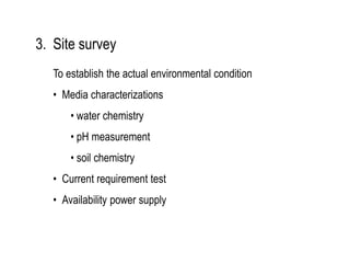
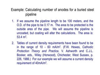
1. Initial considerations including site surveys to determine environmental conditions and structure potentials.
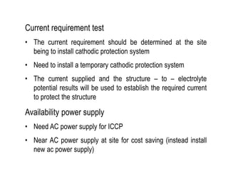
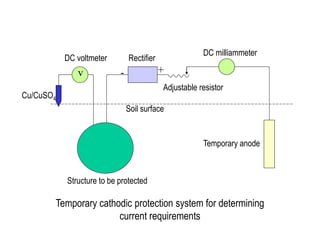
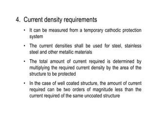
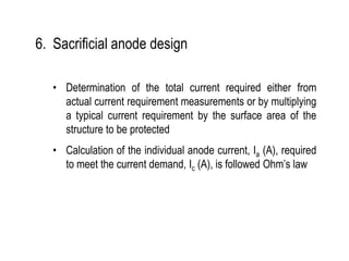
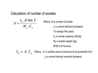
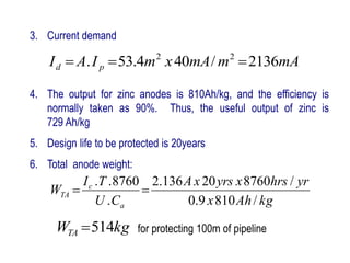
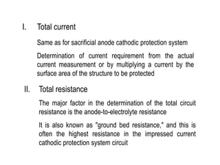
2. Determining current requirements through temporary systems or calculations based on structure area and required current density.
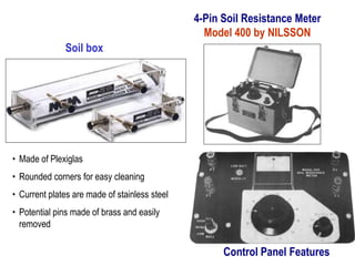
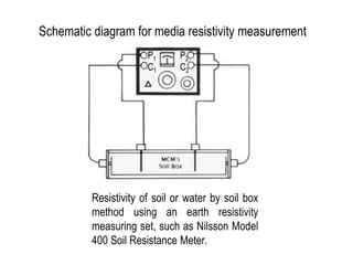
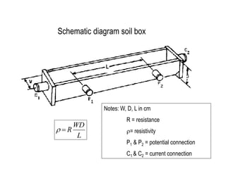
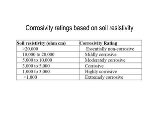
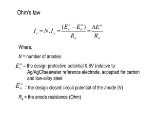
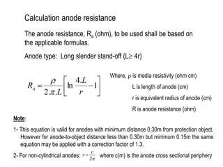
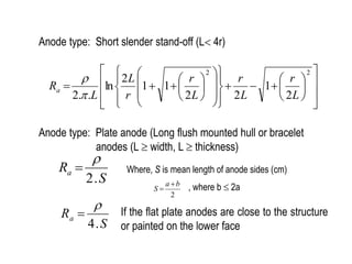
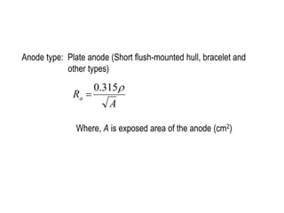
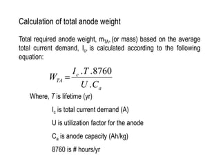
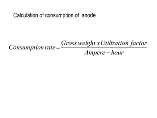
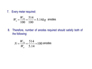
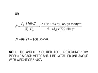
3. Calculations to determine the number, size, and placement of sacrificial anodes needed to meet the current demand based on factors like media resistivity, structure size, and design life.
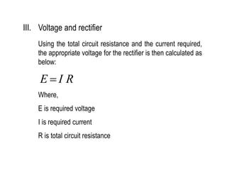
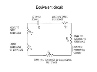
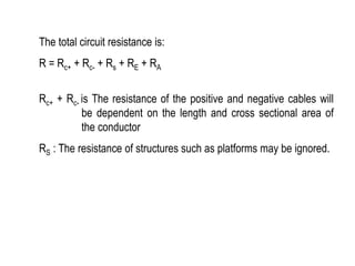
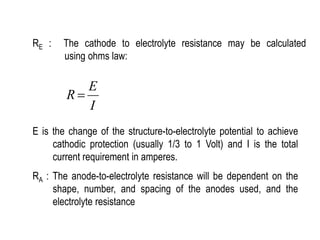
4. For impressed current systems, additional steps are taken to calculate the total system resistance and select a rectifier capable of supplying the required voltage to drive current through the determined resistance.