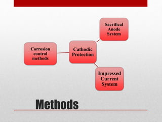
presentation on cathosdic protection......
reference source.....
1. Ashworth V. 4 . 18 Principles of Cathodic Protection. 2010;2:3-10.
2. Zaki Ahmad. • ISBN: 0750659246 • Pub. Date: September 2006 • Publisher: Elsevier Science & Technology Books.; 2006.
3. Baeckmann W von (Walter), Schwenk W (Wilhelm), Prinz W, Baeckmann W von (Walter). Handbook of Cathodic Corrosion Protection : Theory and Practice of Electrochemical Protection Processes. Gulf Pub. Co; 1997.
2. List of Contents
• Definition
• Basis of cathodic protection
• Principle of cathodic protection
• Working of cathodic protection
• Requirements of cathodic protection
• Methods of cathodic protection
• Sacrificial anode system
• Impressed current system
3. Definition
Definition
• Cathodic protection (CP) is a technique used to
control the corrosion of a metal surface by
making it the cathode of an electrochemical cell.
A simple method of protection connects the metal
to be protected to a more easily corroded
"sacrificial metal" to act as the anode.
4. Basis of Cathodic Protection
There must be an anode, a cathode, an electrolyte and a metallic path
for the transfer of electrons.
A source of DC current to supply electrons.
Sufficient direct current should be applied to eliminate the potential
difference between the anode and the cathode.
5. Principle of Cathodic
Protection
• The principle of this method is to force the metal
to behave like a cathode by connecting it to a
powerful anode metal plate.
8. Requirements of Cathodic
Protection
• A voltage of -0.85 V relative to a copper/ saturated copper
sulfate electrode.
• A negative (cathodic) voltage shift of at least 300 mV caused by
the application of cathodic protection current.
• A minimum negative (cathodic) voltage shift of 100 mV
determined by interrupting the current and measuring the
voltage decay.
• A voltage at least as negative (cathodic) as that originally
established at the Tafel segment of the E-log I curve .
• A net protective current from the electrolyte into the surface
9. Methods of Cathodic
Protection
• By coupling a given structure (say Fe) with a more active
metal such as zinc or magnesium. This produces a
galvanic cell in which the active metal works as an anode
and provides a flux of electrons to the structure, which
then becomes the cathode. The cathode is protected and
the anode progressively gets destroyed, and is hence,
called a sacrificial anode.
• The second method involves impressing a direct current
between an inert anode and the structure to be protected.
Since electrons flow to the structure, it is protected from
becoming the source of electrons (anode). In impressed
current systems, the anode is buried and a low voltage DC
current is impressed between the anode and the cathode.
11. Sacrifical Anode System
• The anode is made from a metal alloy with a more
"active" voltage (more negative electrochemical
potential) than the metal of the structure it is
protecting (the cathode). The difference in potential
between the two metals means the sacrificial anode
material corrodes in preference to the structure. This
effectively stops the oxidation reactions on the metal
of the structure being protection.
• Sacrificial anodes generally come in three metals:
magnesium, aluminum, and zinc.
12. Advantage and
Disadvantages
Advantages
• No external power source .
• Easy to install .
• The low voltage and current between the anode and the
surface.
Disadvantages
• Limited current capacity based on the mass of the anode.
• ineffectiveness in high-resistivity environments.
• Increased weight on the protected structure
13. Impressed Current
System
• In this method an impressed current is applied in opposite
direction to nullify the corrosion current and convert the
corroding metal from anode to cathode.
• ICCP systems use anodes connected to a DC source.
• This current is given to insoluble anode like graphite,
stainless steel or scrap iron buried in soil