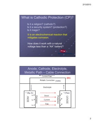
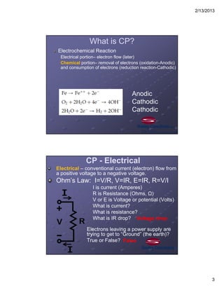
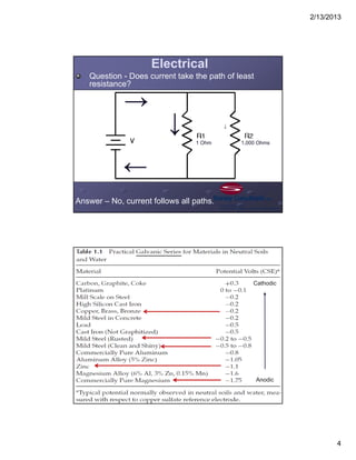
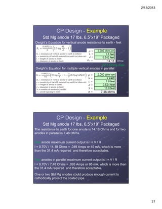
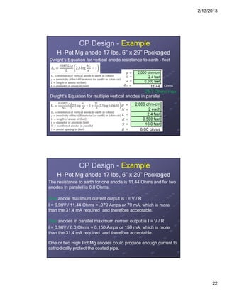
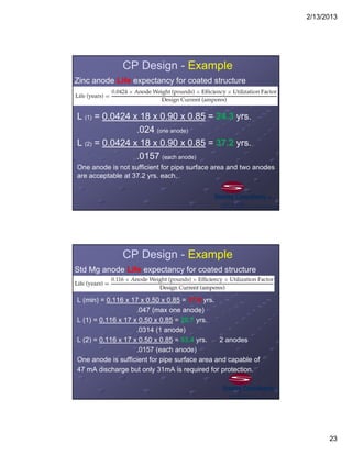
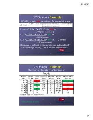
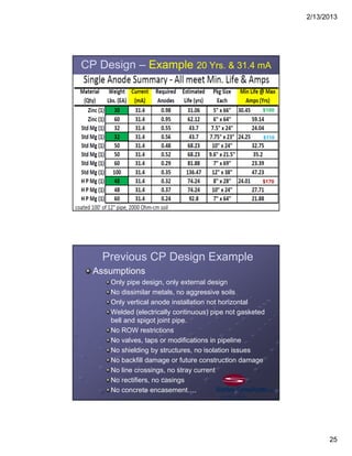
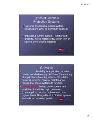
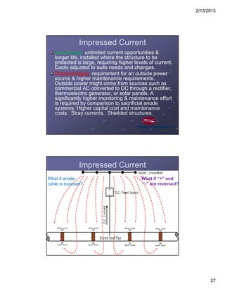
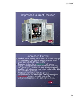
2/13/2013
1
Modern Cathodic
Protection for Piping
Stanley Worcester, P.E.
NACE International Certified Cathodic Protection Specialist
February 20, 2013
worcesterstan@stanleygroup.com
303 925-8307
1.Corrosion Basics
2.Cathodic Protection (CP) Criteria
3.Cathodic Protection Design (galvanic
anodes)
4.Types of Cathodic Protection Systems
5.Protected Structures
6.Structure Isolation
7.Design Considerations
References
Questions
Agenda
2/13/2013
2
Is it a religion? (catholic?)
Is it a security system? (protection?)
Is it magic?
What is Cathodic Protection (CP)?
It is an electrochemical reaction that
mitigates corrosion.
How does it work with a natural
voltage less than a “AA” battery?
Anode, Cathode, Electrolyte,
Metallic Path – Cable Connection
“+”(Pipe)
(Cable)
“-” (Mg, Zn)
Corrosion
Protection
(DC)
2/13/2013
3
What is CP?
Electrochemical Reaction
Electrical portion– electron flow (later)
Chemical portion– removal of electrons (oxidation-Anodic)
and consumption of electrons (reduction reaction-Cathodic)
Anodic
Cathodic
Cathodic
CP - Electrical
Electrical – conventional current (electron) flow from
a positive voltage to a negative voltage.
Ohm’s Law: I=V/R, V=IR, E=IR, R=V/I
I is current (Amperes)
R is Resistance (Ohms, Ω)
V or E is Voltage or potential (Volts)
What is current?
What is resistance?
What is IR drop?
Electrons leaving a power supply are
trying to get to “Ground” (the earth)?
True or False?
Voltage drop
False
2/13/2013
4
Electrical
Question - Does current take the path of least
resistance?
Answer – No, current follows all paths.
1 Ohm 1,000 Ohms
↓ ↓
↓↓
Anodic
Cathodic
2/13/2013
5
New Pipe Corrosion
1. Iron – ductile, soft
2. Carbon - Strong, hard
3. Manganese
4. Silicon
5. Copper
Elements in Carbon Steel Pipe
Corrosion rate of buried steel is approximately 6
mils/yr. or 0.006”/yr. Since 1 mil = 0.001 inches.
Assume pipe will fail when 1/4 of the wall thickness is
gone, a 0.295” pipe wall thickness will fail in 12
years without any cathodic protection.
2/13/2013
6
Galvanic Corrosion
Metallic Path – Dissimilar Metals
Galvanic Corrosion
Metallic Path – Dissimilar Soils
2/13/2013
7
Cathodic Protection (CP)
Cathodic protection is considered to be effective when
active corrosion is transferred from the metal structure
surface to the installed anode. Effectiveness of
transference can be determined by electrical
measurements.
Industry-accepted criteria for effective protection using
these measurements are fully described in various
NACE International publications including the Standard
Practice “SP0169-2007 Control of External Corrosion on
Underground or Submerged Metallic Piping Systems."
Does protection reach
this side of the pipe?
Does Size Matter?
Is one anode
sufficient?
2/13/2013
8
Typical Packaged Galvanic Anode
Backfill Material
50 Ohm-cm
Cathodic Protection (CP)
Anode Shape Difference
Same weight
Low resistance
Large current
Short life
Short &
Wide
L
o
n
g
&
T
h
i
n
Same weight
High resistance
Small current
Long life
2/13/2013
9
Cathodic Protection Criteria
Known as the -0.850 Volt, pipe-to-soil potential
1. This is a measured voltage between the steel structure &
a copper-copper sulfate reference electrode contacting the
electrolyte near the structure. If voltage difference is more
negative than -0.850 Volts, then the structure is considered
protected with consideration of voltage drop. If the value is
more positive than -0.850 Volts, the structure is either
unprotected or only partially protected.
2. A polarized potential with interruption of protection current
(instant off) of -0.850V.
3. 100mV of cathodic polarization. The formation or decay
of polarization is often measured in impressed current
systems.
Underground Permanent
Reference Electrode?
2/13/2013
10
Typical CP Design Questions - Example
What structure do I want to protect?
External surface of underground coated, carbon
steel 12” water pipe, 4’ depth, 100’ long.
What is the surface area?
12” or 1 ft. Diam, 100 Ft long.
PI x D X L = A (Surface Area)
PI (π) = 3.14
D=1 ft.
L=100 ft.
A = 314 square ft.
Typical CP Design Questions - Example
Is the soil corrosive?
Get soil resistivity (ρ)measurement results and
have laboratory chemical analysis performed.
ρ = 2,000 Ohm-cm, Chlorides = 100ppm,
Sulfates = 100ppm, pH = 7.
What else is in the soil?
Know the area, rural, residential, congested, other
structures, rocky, clay, sand, water table, etc…..
What type of CP?
Use galvanic anode design?
2/13/2013
11
Soil Resistivity Measurements
Do I need CP?
Soil
Laboratory
Analysis
Do I need CP?
2/13/2013
12
It’s the Law
Cathodic protection is a mandated
requirement of federal & state regulations
governing underground transmission
pipeline, gas distribution systems,
hazardous liquids & underground
petroleum tanks. These requirements
include installation, monitoring, &
maintenance of cathodic protection
systems*.
*See CFR References
Typical CP Design Questions - Example
How long do I want the anodes to protect
the structure?
Client wants 20 years. (CP System Life)
Which galvanic anode material is best?
Zinc anodes are typically installed in water or soil
with resistivity's less than 2,000 Ohm-cm.
Std Magnesium is typically 1000-5,000 Ohm-cm
Hi-Potential Magnesium is typically 2000 Ohm-cm
and higher.
What is the pipe coating efficiency?
90-98% for field applied coatings
95-99.9% for new factory coatings
2/13/2013
13
Typical CP Design Questions
Does a pipe coating alone provide
enough protection?
Is there a perfect coating?
How long will it last?
Is polyethylene encasement of ductile iron
water pipe enough?
48# Mag Anode
2/13/2013
14
Typical CP Design Questions - Example
Where do I install galvanic anodes?
In permanently moist soil (min 5 ft. deep)
Deeper than bottom of pipe
Protected from future construction
10’ away from pipe
Vertical or horizontal?
How do I connect anodes to pipe?
Exothermic weld lead wire to pipe directly?
Terminate anode lead wire in test station and bond
to pipe lead wire.
2/13/2013
15
Support lead wire and provide slack wire
for settlement
48# Mag Anode
2/13/2013
16
One Galvanic Anode – Direct Connection
What if copper cable is exposed?
Test Station Connection – Anode Bank
2/13/2013
17
Cathodic Protection (CP) Design
Guidelines
Assume a minimum of 1 mA per square
foot required to protect bare structure.
Assume a minimum of 2 mA per square
foot of exposed surface area required to
protect a coated structure.
Current requirements (density) increase
with low soil resistivity, high temperature,
moisture, water flow, dissimilar metals, &
chloride content.
Typical CP Design Questions
What current density do I need?
Reference Army
Technical Manual
TM 5-811-7 1985
2/13/2013
18
CP Design - Example
Current Requirement for coated pipe
95% coated or 5% of 314 sq. ft. of surface area is
bare. Bare surface area is 314 x 0.05 =15.7 sq. ft.
15.7 sq. ft. x 2mA/sq. ft = 31.4 mA.
Driving Potential of anodes
Zinc = -1.10 V – 0.85 (pipe)= 0.25V
Std Mg = -1.55 V – 0.85 (pipe) = 0.70V
Hi-Pot Mg = 1.75 V – 0.85 (pipe) = 0.90V
Maximum anode resistance R=V / I
Zinc = .25/.0314 = 8.0 Ohms
Std Mg = .70/.0314 = 22.3 Ohms
Hi-Pot Mg = .90/.0314 = 28.7 Ohms
CP Design - Example
Find Total Resistance RT of CP system.
Rv = Anode resistance of vertical anode
Rw = Lead wire resistance of 25’ of #12AWG
Rp = Pipe resistance 100’ of 12” diameter
Rc = Coating resistance – Specified by supplier –
(negligible on large structures and this example)
RT = Rv + Rw + Rp + Rc
RT = Rv + 0*
RT = Rv
*Since only the anode resistance is significant in this example.
2/13/2013
19
CP Design - Example
Find lead wire resistance
Lead wire resistance of 25’ of #12AWG, HMWPE
Look up cable table in NEC, Rw = 1.93 Ohms / 1000 ft.
or 0.00193 Ohms per ft. or .0483 Ohms for 25’
(negligible)
Find pipe resistance
Pipe resistance 100’ of 12” diameter
In Peabody Rp = 5.82 microhms / ft. or
0.00000582 Ohms / ft. (negligible)
CP Design - Example
Comparison of 3 anode types
Zinc anode 18 lbs 5”x38” Packaged
Std H-1 Mg 17 lbs 6.5”x19” Packaged
Hi Potential Mg 17 lbs 6”x29” Packaged
Compare these similar weight anodes for
current output and life expectancy.
Do you ever install just one anode?
2/13/2013
20
CP Design - Example
Zinc anode 18 lbs, 5” x 38” Packaged
Dwight’s Equation for vertical anode resistance to earth - feet
Dwight’s Equation for multiple vertical anodes in parallel
Ohms
8.0 Ohms max.
CP Design - Example
Zinc anode 18 lbs, 5” x 38” Packaged
The resistance to earth for one anode is 10.23 Ohms and for two
anodes in parallel is 5.40 Ohms.
One anode maximum current output is I = V / R
I = 0.25V / 10.23 Ohms = .024 Amps or 24 mA, which is less than
the 31.4 mA required.
Two anodes in parallel maximum current output is I = V / R
I = 0.25V / 5.4 Ohms = .046 Amps or 46 mA max or 31.4 / 2 =
15.7 mA each which is acceptable
One zinc anode could not produce enough current to cathodically
protect the coated pipe.
2/13/2013
21
CP Design - Example
Std Mg anode 17 lbs, 6.5”x19” Packaged
Dwight’s Equation for vertical anode resistance to earth - feet
Dwight’s Equation for multiple vertical anodes in parallel
Ohms
22.3 Ohms max.
CP Design - Example
Std Mg anode 17 lbs, 6.5”x19” Packaged
The resistance to earth for one anode is 14.18 Ohms and for two
anodes in parallel is 7.48 Ohms.
One anode maximum current output is I = V / R
I = 0.70V / 14.18 Ohms = .049 Amps or 49 mA, which is more
than the 31.4 mA required and therefore acceptable.
Two anodes in parallel maximum current output is I = V / R
I = 0.70V / 7.48 Ohms = .095 Amps or 95 mA, which is more than
the 31.4 mA required and therefore acceptable.
One or two Std Mg anodes could produce enough current to
cathodically protect the coated pipe.
2/13/2013
22
CP Design - Example
Hi-Pot Mg anode 17 lbs, 6” x 29” Packaged
Dwight’s Equation for vertical anode resistance to earth - feet
Dwight’s Equation for multiple vertical anodes in parallel
Ohms
28.7 Ohms max.
CP Design - Example
Hi-Pot Mg anode 17 lbs, 6” x 29” Packaged
The resistance to earth for one anode is 11.44 Ohms and for two
anodes in parallel is 6.0 Ohms.
One anode maximum current output is I = V / R
I = 0.90V / 11.44 Ohms = .079 Amps or 79 mA, which is more
than the 31.4 mA required and therefore acceptable.
Two anodes in parallel maximum current output is I = V / R
I = 0.90V / 6.0 Ohms = 0.150 Amps or 150 mA, which is more
than the 31.4 mA required and therefore acceptable.
One or two High Pot Mg anodes could produce enough current to
cathodically protect the coated pipe.
2/13/2013
23
CP Design - Example
Zinc anode Life expectancy for coated structure
L (1) = 0.0424 x 18 x 0.90 x 0.85 = 24.3 yrs.
.024 (one anode)
L (2) = 0.0424 x 18 x 0.90 x 0.85 = 37.2 yrs.
.0157 (each anode)
One anode is not sufficient for pipe surface area and two anodes
are acceptable at 37.2 yrs. each.
CP Design - Example
Std Mg anode Life expectancy for coated structure
L (min) = 0.116 x 17 x 0.50 x 0.85 = 17.8 yrs.
.047 (max one anode)
L (1) = 0.116 x 17 x 0.50 x 0.85 = 26.7 yrs.
.0314 (1 anode)
L (2) = 0.116 x 17 x 0.50 x 0.85 = 53.4 yrs. 2 anodes
.0157 (each anode)
One anode is sufficient for pipe surface area and capable of
47 mA discharge but only 31mA is required for protection.
2/13/2013
24
CP Design - Example
Hi-Pot Mg anode Life expectancy for coated structure
L (min) = 0.116 x 17 x 0.50 x 0.85 = 10.6 yrs.
.079 (max one anode)
L (1) = 0.116 x 17 x 0.50 x 0.85 = 26.7 yrs.
.0314 (1 anode)
L (2) = 0.116 x 17 x 0.50 x 0.85 = 53.4 yrs. 2 anodes
.0157 (each anode)
One anode is sufficient for pipe surface area and capable of
79 mA discharge but only 31mA is required for protection.
CP Design - Example
Summary of 3 anode type Comparison
Which Anode is best?
2/13/2013
25
CP Design – Example 20 Yrs. & 31.4 mA
$100
$110
$170
Previous CP Design Example
Assumptions
Only pipe design, only external design
No dissimilar metals, no aggressive soils
Only vertical anode installation not horizontal
Welded (electrically continuous) pipe not gasketed
bell and spigot joint pipe.
No ROW restrictions
No valves, taps or modifications in pipeline
No shielding by structures, no isolation issues
No backfill damage or future construction damage
No line crossings, no stray current
No rectifiers, no casings
No concrete encasement….
2/13/2013
26
Types of Cathodic
Protection Systems
Galvanic or sacrificial anode system.
(magnesium, zinc, or aluminum anodes)
Impressed current system. (rectifier with
graphite, mixed metal oxide, silicon iron or
several other anode materials)
Galvanic
Advantages: flexibility in application, anodes
can be installed (evenly distributed) in a variety
of applications & configurations. No outside
power is required, minimal maintenance
required for these systems to function.
Disadvantages: limited protection current
available, limited life, rapid corrosion
(consumption), require replacement on a
regular basis, Design life of a pipeline system
anode is ten to twenty years.
2/13/2013
27
Impressed Current
Advantages: unlimited current opportunities &
longer life, installed where the structure to be
protected is large, requiring higher levels of current.
Easily adjusted to suite needs and changes.
Disadvantages: requirement for an outside power
source & higher maintenance requirements.
Outside power might come from sources such as
commercial AC converted to DC through a rectifier,
thermoelectric generator, or solar panels. A
significantly higher monitoring & maintenance effort
is required by comparison to sacrificial anode
systems. Higher capital cost and maintenance
costs. Stray currents. Shielded structures.
Impressed Current
What if anode
cable is exposed?
What if “+” and
“-” are reversed?
2/13/2013
28
Impressed Current Rectifier
Impressed Current
External power source that pushes DC current through
long-lasting anodes. Typical source of power is AC
power converted to DC by a rectifier.
Designed for long life at adjustable high current
output. This requires selection of materials with very
low corrosion (consumption) rates, including treated
graphite, high silicon cast iron, mixed metal oxide, & to
a lesser extent, platinum.
Anodes are normally installed in grouped
configurations in the electrolyte. These groupings at
one location (both horizontal & vertical) in
underground application are called groundbeds.
2/13/2013
29
Deep Groundbed
Deep Groundbed Drilling - Rural
2/13/2013
30
Deep Groundbed Drilling - City
2/13/2013
31
High Silicon Cast Iron Anodes
Anode Centralizers
2/13/2013
32
Impressed Current Deep Groundbeds
Advantages: Located in congested areas, less real
estate on small footprint, lower resistance, better
current distribution, reduced shielding and stray
current, less damage caused by construction, no
seasonal variation, anodes can be replaced in
future.
Disadvantages: A higher installation cost, higher
anode inspection or replacement cost, care to
prevent ground water intermixing or contamination.
2/13/2013
33
Structure Junction Box – Rectifier Negative
Anode Junction Box – Rectifier Positive
2/13/2013
34
Cathodically Protected Structures
Underground Pipelines: Both sacrificial & impressed current
systems are used. Federal & state regulations require
cathodic protection for most petroleum or gas pipeline
systems.
Underground Storage Tanks (USTs): required by EPA to
either have functional cathodic protection systems or to be of
a non-corrosive material.
Aboveground Storage Tank (ASTs): bottoms can be
protected from soil-side corrosion with cathodic protection.
Unique problems involved with tank applications include
difficulty of distributing current uniformly over tank bottom &
monitoring effectiveness of systems.
Any metal connected to protected structure. (This requires
additional current).
Above-Ground Storage Tank
2/13/2013
35
Structure Isolation
Protected structures need to be isolated
from other structures by separation,
coatings, or insulated materials.
If isolation is not possible, cathodic
protection anodes can be placed in close
proximity to structure to ensure protection
is achieved.
Insulated Flange Kit
2/13/2013
36
Testing
Design Considerations
Limitations of cathodic protection must be recognized
during the design process. Cathodic protection will be
effective only on metal surfaces in continual contact
with the electrolyte.
Above-ground structures will not be protected.
The distribution of current to desired areas becomes
difficult in congested, shielded or remote areas.
Examples include multiple pipeline right-of-ways,
shorted castings and storage tank bottoms.
2/13/2013
37
Design Considerations
2/13/2013
38
Design Considerations
2/13/2013
39
Stray Current –Parallel Pipelines
Stray Current - Crossing
2/13/2013
40
Testing
Soil resistivity measurements.
Current requirement tests.
Test stations every 500-2000 feet.
Insulated flange kit isolation tests.
Permanent reference electrode tests.
Rectifier voltage adjustments, structure
current resistance, anode currents, current
interruption for instant off readings.
Test Equipment
2/13/2013
41
Portable
Reference
Electrodes
Underground Reference Electrode
2/13/2013
42
Above Ground Test Station
Below Grade Test Station
2/13/2013
43
Below Grade Test Stations
2/13/2013
44
Test Station Terminations
Test Station
2/13/2013
45
Test Station problems
2/13/2013
46
1.Corrosion Basics
2.Cathodic Protection Criteria
3.Cathodic Protection Design (galvanic
anodes)
4.Types of Cathodic Protection Systems
5.Protected Structures
6.Structure Isolation
7.Design Considerations
Summary
References
“Control of Pipeline Corrosion” A.W. Peabody.
NACE Std SP0169-2007 Control of External Corrosion on
Underground or Submerged Metallic Piping Systems.
Code of Federal Regulations CFR 49.192-2012 Transportation
of Natural and other Gas by Pipeline.
Code of Federal Regulations CFR 49.195-2012 Transportation
of Hazardous Liquids by Pipeline.
“Galvanic Corrosion” Harvey P. Hack.
“NACE Corrosion Engineer’s Reference Book” R. S. Treseder.
ASTM G57 Soil resistivity using the Wenner 4-pin method.
2/13/2013
47
References
ARMY Technical Manual TM 5-811-7, 1995 Electrical Design,
Cathodic Protection.
USACE Engineering Manual EM 1110-2-2704, 2004 Cathodic
Protection systems for Civil Works Structures.
NACE Std RP0193-2001 External Cathodic Protection of On-
Grade Carbon Steel Storage Tank Bottoms.
“NACE Std RP0572-2001 Design, Installation, Operation, and
Maintenance of Impressed Current Deep Ground beds.
NFPA 70-2011 National Electric Code (NEC)
IEEE Std 81. IEEE Guide for Measuring Earth Resistivity,
Ground Impedance, and Earth Surface Potentials of a Ground
System.
Questions?

CorrosionCathProtBasicDesignSATX

  • 1.
    2/13/2013 1 Modern Cathodic Protection forPiping Stanley Worcester, P.E. NACE International Certified Cathodic Protection Specialist February 20, 2013 worcesterstan@stanleygroup.com 303 925-8307 1.Corrosion Basics 2.Cathodic Protection (CP) Criteria 3.Cathodic Protection Design (galvanic anodes) 4.Types of Cathodic Protection Systems 5.Protected Structures 6.Structure Isolation 7.Design Considerations References Questions Agenda
  • 2.
    2/13/2013 2 Is it areligion? (catholic?) Is it a security system? (protection?) Is it magic? What is Cathodic Protection (CP)? It is an electrochemical reaction that mitigates corrosion. How does it work with a natural voltage less than a “AA” battery? Anode, Cathode, Electrolyte, Metallic Path – Cable Connection “+”(Pipe) (Cable) “-” (Mg, Zn) Corrosion Protection (DC)
  • 3.
    2/13/2013 3 What is CP? ElectrochemicalReaction Electrical portion– electron flow (later) Chemical portion– removal of electrons (oxidation-Anodic) and consumption of electrons (reduction reaction-Cathodic) Anodic Cathodic Cathodic CP - Electrical Electrical – conventional current (electron) flow from a positive voltage to a negative voltage. Ohm’s Law: I=V/R, V=IR, E=IR, R=V/I I is current (Amperes) R is Resistance (Ohms, Ω) V or E is Voltage or potential (Volts) What is current? What is resistance? What is IR drop? Electrons leaving a power supply are trying to get to “Ground” (the earth)? True or False? Voltage drop False
  • 4.
    2/13/2013 4 Electrical Question - Doescurrent take the path of least resistance? Answer – No, current follows all paths. 1 Ohm 1,000 Ohms ↓ ↓ ↓↓ Anodic Cathodic
  • 5.
    2/13/2013 5 New Pipe Corrosion 1.Iron – ductile, soft 2. Carbon - Strong, hard 3. Manganese 4. Silicon 5. Copper Elements in Carbon Steel Pipe Corrosion rate of buried steel is approximately 6 mils/yr. or 0.006”/yr. Since 1 mil = 0.001 inches. Assume pipe will fail when 1/4 of the wall thickness is gone, a 0.295” pipe wall thickness will fail in 12 years without any cathodic protection.
  • 6.
    2/13/2013 6 Galvanic Corrosion Metallic Path– Dissimilar Metals Galvanic Corrosion Metallic Path – Dissimilar Soils
  • 7.
    2/13/2013 7 Cathodic Protection (CP) Cathodicprotection is considered to be effective when active corrosion is transferred from the metal structure surface to the installed anode. Effectiveness of transference can be determined by electrical measurements. Industry-accepted criteria for effective protection using these measurements are fully described in various NACE International publications including the Standard Practice “SP0169-2007 Control of External Corrosion on Underground or Submerged Metallic Piping Systems." Does protection reach this side of the pipe? Does Size Matter? Is one anode sufficient?
  • 8.
    2/13/2013 8 Typical Packaged GalvanicAnode Backfill Material 50 Ohm-cm Cathodic Protection (CP) Anode Shape Difference Same weight Low resistance Large current Short life Short & Wide L o n g & T h i n Same weight High resistance Small current Long life
  • 9.
    2/13/2013 9 Cathodic Protection Criteria Knownas the -0.850 Volt, pipe-to-soil potential 1. This is a measured voltage between the steel structure & a copper-copper sulfate reference electrode contacting the electrolyte near the structure. If voltage difference is more negative than -0.850 Volts, then the structure is considered protected with consideration of voltage drop. If the value is more positive than -0.850 Volts, the structure is either unprotected or only partially protected. 2. A polarized potential with interruption of protection current (instant off) of -0.850V. 3. 100mV of cathodic polarization. The formation or decay of polarization is often measured in impressed current systems. Underground Permanent Reference Electrode?
  • 10.
    2/13/2013 10 Typical CP DesignQuestions - Example What structure do I want to protect? External surface of underground coated, carbon steel 12” water pipe, 4’ depth, 100’ long. What is the surface area? 12” or 1 ft. Diam, 100 Ft long. PI x D X L = A (Surface Area) PI (π) = 3.14 D=1 ft. L=100 ft. A = 314 square ft. Typical CP Design Questions - Example Is the soil corrosive? Get soil resistivity (ρ)measurement results and have laboratory chemical analysis performed. ρ = 2,000 Ohm-cm, Chlorides = 100ppm, Sulfates = 100ppm, pH = 7. What else is in the soil? Know the area, rural, residential, congested, other structures, rocky, clay, sand, water table, etc….. What type of CP? Use galvanic anode design?
  • 11.
    2/13/2013 11 Soil Resistivity Measurements DoI need CP? Soil Laboratory Analysis Do I need CP?
  • 12.
    2/13/2013 12 It’s the Law Cathodicprotection is a mandated requirement of federal & state regulations governing underground transmission pipeline, gas distribution systems, hazardous liquids & underground petroleum tanks. These requirements include installation, monitoring, & maintenance of cathodic protection systems*. *See CFR References Typical CP Design Questions - Example How long do I want the anodes to protect the structure? Client wants 20 years. (CP System Life) Which galvanic anode material is best? Zinc anodes are typically installed in water or soil with resistivity's less than 2,000 Ohm-cm. Std Magnesium is typically 1000-5,000 Ohm-cm Hi-Potential Magnesium is typically 2000 Ohm-cm and higher. What is the pipe coating efficiency? 90-98% for field applied coatings 95-99.9% for new factory coatings
  • 13.
    2/13/2013 13 Typical CP DesignQuestions Does a pipe coating alone provide enough protection? Is there a perfect coating? How long will it last? Is polyethylene encasement of ductile iron water pipe enough? 48# Mag Anode
  • 14.
    2/13/2013 14 Typical CP DesignQuestions - Example Where do I install galvanic anodes? In permanently moist soil (min 5 ft. deep) Deeper than bottom of pipe Protected from future construction 10’ away from pipe Vertical or horizontal? How do I connect anodes to pipe? Exothermic weld lead wire to pipe directly? Terminate anode lead wire in test station and bond to pipe lead wire.
  • 15.
    2/13/2013 15 Support lead wireand provide slack wire for settlement 48# Mag Anode
  • 16.
    2/13/2013 16 One Galvanic Anode– Direct Connection What if copper cable is exposed? Test Station Connection – Anode Bank
  • 17.
    2/13/2013 17 Cathodic Protection (CP)Design Guidelines Assume a minimum of 1 mA per square foot required to protect bare structure. Assume a minimum of 2 mA per square foot of exposed surface area required to protect a coated structure. Current requirements (density) increase with low soil resistivity, high temperature, moisture, water flow, dissimilar metals, & chloride content. Typical CP Design Questions What current density do I need? Reference Army Technical Manual TM 5-811-7 1985
  • 18.
    2/13/2013 18 CP Design -Example Current Requirement for coated pipe 95% coated or 5% of 314 sq. ft. of surface area is bare. Bare surface area is 314 x 0.05 =15.7 sq. ft. 15.7 sq. ft. x 2mA/sq. ft = 31.4 mA. Driving Potential of anodes Zinc = -1.10 V – 0.85 (pipe)= 0.25V Std Mg = -1.55 V – 0.85 (pipe) = 0.70V Hi-Pot Mg = 1.75 V – 0.85 (pipe) = 0.90V Maximum anode resistance R=V / I Zinc = .25/.0314 = 8.0 Ohms Std Mg = .70/.0314 = 22.3 Ohms Hi-Pot Mg = .90/.0314 = 28.7 Ohms CP Design - Example Find Total Resistance RT of CP system. Rv = Anode resistance of vertical anode Rw = Lead wire resistance of 25’ of #12AWG Rp = Pipe resistance 100’ of 12” diameter Rc = Coating resistance – Specified by supplier – (negligible on large structures and this example) RT = Rv + Rw + Rp + Rc RT = Rv + 0* RT = Rv *Since only the anode resistance is significant in this example.
  • 19.
    2/13/2013 19 CP Design -Example Find lead wire resistance Lead wire resistance of 25’ of #12AWG, HMWPE Look up cable table in NEC, Rw = 1.93 Ohms / 1000 ft. or 0.00193 Ohms per ft. or .0483 Ohms for 25’ (negligible) Find pipe resistance Pipe resistance 100’ of 12” diameter In Peabody Rp = 5.82 microhms / ft. or 0.00000582 Ohms / ft. (negligible) CP Design - Example Comparison of 3 anode types Zinc anode 18 lbs 5”x38” Packaged Std H-1 Mg 17 lbs 6.5”x19” Packaged Hi Potential Mg 17 lbs 6”x29” Packaged Compare these similar weight anodes for current output and life expectancy. Do you ever install just one anode?
  • 20.
    2/13/2013 20 CP Design -Example Zinc anode 18 lbs, 5” x 38” Packaged Dwight’s Equation for vertical anode resistance to earth - feet Dwight’s Equation for multiple vertical anodes in parallel Ohms 8.0 Ohms max. CP Design - Example Zinc anode 18 lbs, 5” x 38” Packaged The resistance to earth for one anode is 10.23 Ohms and for two anodes in parallel is 5.40 Ohms. One anode maximum current output is I = V / R I = 0.25V / 10.23 Ohms = .024 Amps or 24 mA, which is less than the 31.4 mA required. Two anodes in parallel maximum current output is I = V / R I = 0.25V / 5.4 Ohms = .046 Amps or 46 mA max or 31.4 / 2 = 15.7 mA each which is acceptable One zinc anode could not produce enough current to cathodically protect the coated pipe.
  • 21.
    2/13/2013 21 CP Design -Example Std Mg anode 17 lbs, 6.5”x19” Packaged Dwight’s Equation for vertical anode resistance to earth - feet Dwight’s Equation for multiple vertical anodes in parallel Ohms 22.3 Ohms max. CP Design - Example Std Mg anode 17 lbs, 6.5”x19” Packaged The resistance to earth for one anode is 14.18 Ohms and for two anodes in parallel is 7.48 Ohms. One anode maximum current output is I = V / R I = 0.70V / 14.18 Ohms = .049 Amps or 49 mA, which is more than the 31.4 mA required and therefore acceptable. Two anodes in parallel maximum current output is I = V / R I = 0.70V / 7.48 Ohms = .095 Amps or 95 mA, which is more than the 31.4 mA required and therefore acceptable. One or two Std Mg anodes could produce enough current to cathodically protect the coated pipe.
  • 22.
    2/13/2013 22 CP Design -Example Hi-Pot Mg anode 17 lbs, 6” x 29” Packaged Dwight’s Equation for vertical anode resistance to earth - feet Dwight’s Equation for multiple vertical anodes in parallel Ohms 28.7 Ohms max. CP Design - Example Hi-Pot Mg anode 17 lbs, 6” x 29” Packaged The resistance to earth for one anode is 11.44 Ohms and for two anodes in parallel is 6.0 Ohms. One anode maximum current output is I = V / R I = 0.90V / 11.44 Ohms = .079 Amps or 79 mA, which is more than the 31.4 mA required and therefore acceptable. Two anodes in parallel maximum current output is I = V / R I = 0.90V / 6.0 Ohms = 0.150 Amps or 150 mA, which is more than the 31.4 mA required and therefore acceptable. One or two High Pot Mg anodes could produce enough current to cathodically protect the coated pipe.
  • 23.
    2/13/2013 23 CP Design -Example Zinc anode Life expectancy for coated structure L (1) = 0.0424 x 18 x 0.90 x 0.85 = 24.3 yrs. .024 (one anode) L (2) = 0.0424 x 18 x 0.90 x 0.85 = 37.2 yrs. .0157 (each anode) One anode is not sufficient for pipe surface area and two anodes are acceptable at 37.2 yrs. each. CP Design - Example Std Mg anode Life expectancy for coated structure L (min) = 0.116 x 17 x 0.50 x 0.85 = 17.8 yrs. .047 (max one anode) L (1) = 0.116 x 17 x 0.50 x 0.85 = 26.7 yrs. .0314 (1 anode) L (2) = 0.116 x 17 x 0.50 x 0.85 = 53.4 yrs. 2 anodes .0157 (each anode) One anode is sufficient for pipe surface area and capable of 47 mA discharge but only 31mA is required for protection.
  • 24.
    2/13/2013 24 CP Design -Example Hi-Pot Mg anode Life expectancy for coated structure L (min) = 0.116 x 17 x 0.50 x 0.85 = 10.6 yrs. .079 (max one anode) L (1) = 0.116 x 17 x 0.50 x 0.85 = 26.7 yrs. .0314 (1 anode) L (2) = 0.116 x 17 x 0.50 x 0.85 = 53.4 yrs. 2 anodes .0157 (each anode) One anode is sufficient for pipe surface area and capable of 79 mA discharge but only 31mA is required for protection. CP Design - Example Summary of 3 anode type Comparison Which Anode is best?
  • 25.
    2/13/2013 25 CP Design –Example 20 Yrs. & 31.4 mA $100 $110 $170 Previous CP Design Example Assumptions Only pipe design, only external design No dissimilar metals, no aggressive soils Only vertical anode installation not horizontal Welded (electrically continuous) pipe not gasketed bell and spigot joint pipe. No ROW restrictions No valves, taps or modifications in pipeline No shielding by structures, no isolation issues No backfill damage or future construction damage No line crossings, no stray current No rectifiers, no casings No concrete encasement….
  • 26.
    2/13/2013 26 Types of Cathodic ProtectionSystems Galvanic or sacrificial anode system. (magnesium, zinc, or aluminum anodes) Impressed current system. (rectifier with graphite, mixed metal oxide, silicon iron or several other anode materials) Galvanic Advantages: flexibility in application, anodes can be installed (evenly distributed) in a variety of applications & configurations. No outside power is required, minimal maintenance required for these systems to function. Disadvantages: limited protection current available, limited life, rapid corrosion (consumption), require replacement on a regular basis, Design life of a pipeline system anode is ten to twenty years.
  • 27.
    2/13/2013 27 Impressed Current Advantages: unlimitedcurrent opportunities & longer life, installed where the structure to be protected is large, requiring higher levels of current. Easily adjusted to suite needs and changes. Disadvantages: requirement for an outside power source & higher maintenance requirements. Outside power might come from sources such as commercial AC converted to DC through a rectifier, thermoelectric generator, or solar panels. A significantly higher monitoring & maintenance effort is required by comparison to sacrificial anode systems. Higher capital cost and maintenance costs. Stray currents. Shielded structures. Impressed Current What if anode cable is exposed? What if “+” and “-” are reversed?
  • 28.
    2/13/2013 28 Impressed Current Rectifier ImpressedCurrent External power source that pushes DC current through long-lasting anodes. Typical source of power is AC power converted to DC by a rectifier. Designed for long life at adjustable high current output. This requires selection of materials with very low corrosion (consumption) rates, including treated graphite, high silicon cast iron, mixed metal oxide, & to a lesser extent, platinum. Anodes are normally installed in grouped configurations in the electrolyte. These groupings at one location (both horizontal & vertical) in underground application are called groundbeds.
  • 29.
  • 30.
    2/13/2013 30 Deep Groundbed Drilling- City Deep Groundbed Drilling - City
  • 31.
    2/13/2013 31 High Silicon CastIron Anodes Anode Centralizers
  • 32.
    2/13/2013 32 Impressed Current DeepGroundbeds Advantages: Located in congested areas, less real estate on small footprint, lower resistance, better current distribution, reduced shielding and stray current, less damage caused by construction, no seasonal variation, anodes can be replaced in future. Disadvantages: A higher installation cost, higher anode inspection or replacement cost, care to prevent ground water intermixing or contamination.
  • 33.
    2/13/2013 33 Structure Junction Box– Rectifier Negative Anode Junction Box – Rectifier Positive
  • 34.
    2/13/2013 34 Cathodically Protected Structures UndergroundPipelines: Both sacrificial & impressed current systems are used. Federal & state regulations require cathodic protection for most petroleum or gas pipeline systems. Underground Storage Tanks (USTs): required by EPA to either have functional cathodic protection systems or to be of a non-corrosive material. Aboveground Storage Tank (ASTs): bottoms can be protected from soil-side corrosion with cathodic protection. Unique problems involved with tank applications include difficulty of distributing current uniformly over tank bottom & monitoring effectiveness of systems. Any metal connected to protected structure. (This requires additional current). Above-Ground Storage Tank
  • 35.
    2/13/2013 35 Structure Isolation Protected structuresneed to be isolated from other structures by separation, coatings, or insulated materials. If isolation is not possible, cathodic protection anodes can be placed in close proximity to structure to ensure protection is achieved. Insulated Flange Kit
  • 36.
    2/13/2013 36 Testing Design Considerations Limitations ofcathodic protection must be recognized during the design process. Cathodic protection will be effective only on metal surfaces in continual contact with the electrolyte. Above-ground structures will not be protected. The distribution of current to desired areas becomes difficult in congested, shielded or remote areas. Examples include multiple pipeline right-of-ways, shorted castings and storage tank bottoms.
  • 37.
  • 38.
  • 39.
    2/13/2013 39 Stray Current –ParallelPipelines Stray Current - Crossing
  • 40.
    2/13/2013 40 Testing Soil resistivity measurements. Currentrequirement tests. Test stations every 500-2000 feet. Insulated flange kit isolation tests. Permanent reference electrode tests. Rectifier voltage adjustments, structure current resistance, anode currents, current interruption for instant off readings. Test Equipment
  • 41.
  • 42.
    2/13/2013 42 Above Ground TestStation Below Grade Test Station
  • 43.
    2/13/2013 43 Below Grade TestStations Below Grade Test Stations
  • 44.
  • 45.
  • 46.
    2/13/2013 46 1.Corrosion Basics 2.Cathodic ProtectionCriteria 3.Cathodic Protection Design (galvanic anodes) 4.Types of Cathodic Protection Systems 5.Protected Structures 6.Structure Isolation 7.Design Considerations Summary References “Control of Pipeline Corrosion” A.W. Peabody. NACE Std SP0169-2007 Control of External Corrosion on Underground or Submerged Metallic Piping Systems. Code of Federal Regulations CFR 49.192-2012 Transportation of Natural and other Gas by Pipeline. Code of Federal Regulations CFR 49.195-2012 Transportation of Hazardous Liquids by Pipeline. “Galvanic Corrosion” Harvey P. Hack. “NACE Corrosion Engineer’s Reference Book” R. S. Treseder. ASTM G57 Soil resistivity using the Wenner 4-pin method.
  • 47.
    2/13/2013 47 References ARMY Technical ManualTM 5-811-7, 1995 Electrical Design, Cathodic Protection. USACE Engineering Manual EM 1110-2-2704, 2004 Cathodic Protection systems for Civil Works Structures. NACE Std RP0193-2001 External Cathodic Protection of On- Grade Carbon Steel Storage Tank Bottoms. “NACE Std RP0572-2001 Design, Installation, Operation, and Maintenance of Impressed Current Deep Ground beds. NFPA 70-2011 National Electric Code (NEC) IEEE Std 81. IEEE Guide for Measuring Earth Resistivity, Ground Impedance, and Earth Surface Potentials of a Ground System. Questions?