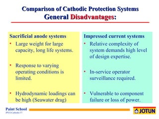
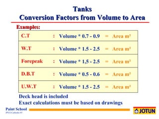
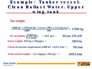
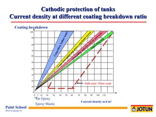
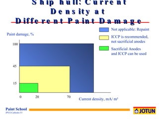
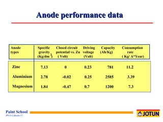
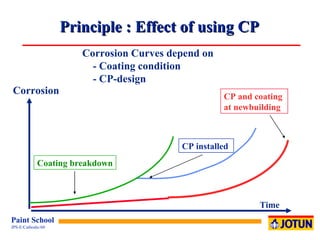
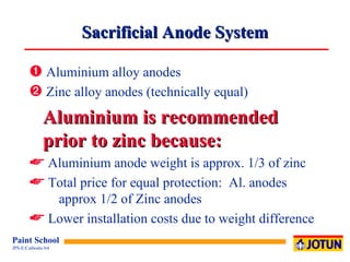
SlideShare a Scribd company logo
1 of 73
Organisation Chart Jotun Cathodic Protection Jotun Cathodic Protection Jotun Decorative ( Scandinavia) Jotun Protective Coatings Jotun Decorative Paints Jotun Marine Coatings Jotun Paints Jotun Powder Coatings Jotun Group
Corrosion of a metal or alloy ,[object Object],[object Object],[object Object],[object Object],2+
What is cathodic protection ? ,[object Object],[object Object],[object Object],[object Object],[object Object]
How to protect a structure ,[object Object],[object Object],[object Object],[object Object],[object Object]
Type of Products ,[object Object],[object Object],[object Object],[object Object]
[object Object],[object Object],[object Object],[object Object],[object Object],[object Object],[object Object],Type of   Sacrificial Anodes
Type of Products ,[object Object],[object Object],[object Object],[object Object],[object Object],[object Object]
Type of Services ,[object Object],[object Object],[object Object],[object Object],[object Object]
Type of Products and Services ,[object Object],[object Object],[object Object],[object Object],[object Object],[object Object],[object Object],[object Object]
[object Object],[object Object],[object Object],[object Object],[object Object],[object Object],[object Object],Type of Products
Type of products ,[object Object],[object Object],[object Object],[object Object]
Type of Products ,[object Object],[object Object],[object Object]
For Norway Objects to be Protected: ,[object Object],[object Object],[object Object],[object Object],[object Object],[object Object],[object Object]
Objects to be Protected: ,[object Object],[object Object],[object Object],[object Object],[object Object]
Marine  Objects to be Protected: ,[object Object],[object Object],[object Object],[object Object],[object Object]
Norwegian Sector. Offshore and Industry Objects to be Protected : ,[object Object],[object Object],[object Object],[object Object],[object Object],[object Object],[object Object],[object Object],[object Object],[object Object],[object Object]
Offshore and Industry Objects to be Protected: ,[object Object],[object Object],[object Object],[object Object],[object Object],[object Object],[object Object],[object Object],[object Object]
[object Object],[object Object],[object Object],[object Object],Energy Corrosion and corrosion protection Time E 1 E 2 Iron ore Refining Rust = Iron ore Corrosion Pure metal  or an Alloy Cathodic protection Energy offered  by Cathodic  protection Coating  reduces corrosion rate
Freely Corroding Steel Cathode 2 e - Anode Cathode Sea water (electrolyte) 2 e - 2 e - 2 e - Steel plate - Fe 2+ ½  O 2  + H 2 O + 2e     2OH  - ½  O 2  + H 2 O + 2e     2OH  - -
Potential, mV vs. Cu/CuSO 4   Zn -580  +500  Freely corroding steel -700  -800 +250   Mixed potential ( Protection potential) -900 -1000 -1080   0  Freely corroding Zinc The Principle of Cathodic Protection Potentials vs. different Reference Electrodes
Cathodic Protection Steel protected by a Sacrificial anode A calcareous deposit is formed on the steel surface 2  e Steel Zinc Zn = Zn  + 2 e O 2 2+  - - ½  O 2  + H 2 O + 2e     2OH  - -
Steel Current Source Current O 2 2  e- Permanent anode Cathodic protection Impressed current system A calcareous deposit is formed on the steel surface Reaction at the cathode ½  O 2  + H 2 O + 2e     2OH  - - Reaction at the anode 2  Cl     ½ Cl 2   + 2e H 2 O     2H  + ½ O  + 2e - - - +
Rapid corrosion General corrosion Some corrosion 100%  Cathodic protection  Overprotection Possible coating damage Corrosion Potentials in Seawater Zinc, Ag/Ag Cl and Cu/CuSO 4  R eference Electrodes Increasing polarisation Ag / Ag Cl Zinc + 0.50 - 0.25 + 0.0 + 0.25 - 0.55 - 1.30 -1.05 - 0.80 Potentials in volt - 0.60 - 1.35 -1.10 - 0.85 Cu / CuSO 4
Full cathodic protection (Steel surface passivated) Free corrosion of steel Corrosion reduction , %  vs  Zn  450   400   350  300   250  mV vs Ag/AgC1  -600   -650   -700  -750  -800  mV  Reduction of corrosion rate of steel by cathodic protection. Moving seawater Negative polarisation, mV 0 50 87,5 0 50  100  150  200 Actual potential  of the steel
Marine Necessary Information to do a CP Design ,[object Object],[object Object],[object Object],[object Object],[object Object],[object Object],[object Object],[object Object],[object Object]
Marine Design Criteria  ,[object Object],[object Object],[object Object],[object Object],[object Object],[object Object],[object Object]
Protective Design criteria ,[object Object],[object Object],[object Object],[object Object],[object Object],[object Object],[object Object],[object Object],[object Object],[object Object]
Current Density Requirement  Depends On: ,[object Object],[object Object],[object Object],[object Object],[object Object],[object Object],[object Object],[object Object],[object Object],[object Object],[object Object]
Sacrificial Anode material selection ,[object Object],[object Object],[object Object],[object Object],[object Object],[object Object],[object Object],[object Object],[object Object],[object Object],[object Object],[object Object],[object Object]
Initial/final design current densities in A/m 2 Tropical (> 20  o C) Sub-Tropical (12-20  o C) Temperate (7 - 12  o C) Arctic (< 7  o C) 0.150 0.090 0.170 0.110 0.200 0.130 0.250 0.170 0.130 0.080 0.150 0.090 0.180 0.110 0.220 0.130 Depth (m) 0  -  30 >  30 Current density requirement  acc. to DNV RP B401 (1993)
Me4an (average)  design current densities in A/m 2 0  -  30 >  30 0.070 0.080 0.100 0.120 1) 0.060 0.070 0.080 0.100 1) Effect of any ice scouring are not included Current density requirement  acc. to DNV RP B401 (1993) Tropical (> 20  o C) Sub-Tropical (12-20  o C) Temperate (7 - 12  o C) Arctic (< 7  o C) Depth ( m)
Coating Categories Acc. to DNV RP B401 (1993) ,[object Object],[object Object],[object Object],[object Object],Category III: One layer of primer coat, plus minimum two layers of intermediate/top coats, minimum 300 microns nominal DFT Category IV: One layer of primer coat, plus minimum three layers of intermediate top coats, minimum 450 microns nominal DFT.
Coating Category Depth (m) I  II  III  IV k 1  = 0.10 k 2 0 - 30  0.10  0.03  0.015  0.012 >  30  0.05  0.02  0.012  0.012 k 1  = 0.05 k 2 k 1  = 0.02 k 2 k 1  = 0.02 k 2 where fc   = coating break down factor t   = coating lifetime k 1  and k 2  = constants dependent on coating properties f c  =  k 1 + k 2  t Coating Break Down Factor Acc. to DNV RP B401 (1993)
Protective Design Sacrificial Anode System ,[object Object],[object Object],[object Object],[object Object],[object Object],[object Object],[object Object],[object Object],[object Object],[object Object],[object Object],[object Object],[object Object],[object Object],[object Object],[object Object],[object Object],[object Object],[object Object],[object Object]
Jotun Anode Alloys ,[object Object],[object Object],[object Object],[object Object],[object Object],[object Object],[object Object],[object Object],[object Object],[object Object],[object Object],[object Object],[object Object],[object Object],[object Object],[object Object],[object Object]
Comparison of Cathodic Protection Systems  General  Advantages : ,[object Object],[object Object],[object Object],[object Object],[object Object],[object Object],[object Object],[object Object],[object Object]
Comparison of Cathodic Protection Systems General  Disadvantages : ,[object Object],[object Object],[object Object],[object Object],[object Object],[object Object],[object Object],[object Object]
Why Choose an ICCP System on Hull ,[object Object],[object Object],[object Object],[object Object],[object Object],[object Object],[object Object]
Why Choose a SACP System on Hull ,[object Object],[object Object],[object Object],[object Object]
Lifecycle Cost of CP Systems 13000 DWT Car Carrier 0 10,000 20,000 30,000 40,000 50,000 60,000 70,000 80,000 90,000 USD ICCP Al Zn 0  1  2  3  4  5  6  7  8  9  10  11  12  13  14  15  Years  Indicates Dry-docking Replacement of an ICCP component Anodes and Reference electrodes can be replaced whilst in service. Normally, this is carried out at the dry-docking
Life Cycle Cost of CP Systems Panamax Bulkcarrier 0 20,000 40,000 60,000 80,000 100,000 120,000 140,000 160,000 USD ICCP Al Zn 0  1  2  3  4  5  6  7  8  9  10  11  12  13  14  15  Years  Indicates Dry-docking Replacement of an ICCP component Anodes and Reference electrodes can be replaced whilst in service. Normally, this is carried out at the dry-docking
Cathodic Protection of  Ballast Water Tanks ,[object Object],[object Object],[object Object],[object Object]
Tanks:  Lloyd's register  DNV Segregated ballast  108  100  - 110  Dirty ballast  86  40  -  60 Washed cargo  108  80  -  90 Top wing  120  120 Coated (epoxy)  5  5 - 10 Soft Coats  20 - 40 Current density criteria mA/m 2 Current density Design Criteria
Example:  Tanker vessel.  Clean ballast water. Upper wing tank ,[object Object],[object Object],[object Object],[object Object],[object Object],[object Object],[object Object],[object Object],[object Object],[object Object],[object Object]
Tanks Conversion Factors from Volume to Area C.T : W.T : Forepeak : D.B.T : U.W.T : Volume * 0.7 - 0.9 Volume * 1.5 - 2.5 Volume * 1,5 - 2.5 Volume * 0.5 - 0.6 Volume * 1.5 - 2.5 =  Area m²  =  Area m² =  Area m² =  Area m² =  Area m² Examples: Deck head is included Exact calculations must be based on drawings
Net weight: 6400  m 2   x 120 mA/m 2   x 4 yrs x 50% x 11,2 kg/A.yr ------------------------------------------------------  =  17203  kg 1000  100 17203  kg. No. of anodes : ---------------  =  812  pcs :  812  pcs  ZTL-230 21,2  kg/pc Gross weight :  812 kg x 23kg/pcs  =  18676  kg Check  of current requirement: 6400 m 2   x 0,12 A/m 2   =  768  Amp Total current output   : 1,3 Amp/pc x 812 pcs  =  1055,6  Amp Example:  Tanker vessel.  Clean Ballast Water. Upper wing tank
[object Object],[object Object],[object Object],[object Object],Design of Sacrificial Anode System  Double Bottom and Other Narrow Tanks
[object Object],[object Object],[object Object],[object Object],[object Object],[object Object],Design of Sacrificial Anode System  Double Bottom and Other Narrow Tanks Number of compartments (pc)
Example:  Tanker vessel.  Clean ballast water. Double Bottom Tank ,[object Object],[object Object],[object Object],[object Object],[object Object],[object Object],[object Object],[object Object],[object Object],[object Object],[object Object]
Net weight: 6400  m 2   x 120 mA/m 2   x 4 yrs x 50% x 11,2 kg/A.yr ------------------------------------------------------  =  17203  kg 1000  100 17203  kg. No. of anodes : ---------------  =  812  pcs :  812  pcs  ZTL-230 21,2  kg/pc Gross weight :  812 kg x 23kg/pcs  =  18676  kg Check  of current requirement: 6400 m 2   x 0,12 A/m 2   =  768  Amp Total current output   : 1,3 Amp/pc x 812 pcs  =  1055,6  Amp Example:  Tanker vessel.  Clean Ballast Water. Double Bottom Tank
ICCP - Log report Readings Current Output Development With Time 100  - 80  - 60  - 40  - 20  - |  |  |  |  |  |  1  2  3  4  5  6  System capacity Amp. Years 1.  docking 2..  docking 3.  docking Grounding (Loss of coating) Example
Cathodic protection of tanks Current density at different coating breakdown ratio Current density mA/m² 70 60 50 40 30 20 10 2 80 90 Tar Epoxy  Epoxy Mastic Upper Wing tank 0  5  10  20  30  40  50  60  70  80  90  100  110  120 100 Cargo/dirty ballast tanks Clean ballast tanks fore-and aft. peak tanks Cargo/clean ballast tank slower wing/double bottom Soft coat / Flow coat Coating breakdown
Ship hull: Current Density at  Different Paint Damage Current density, mA/ m² Paint damage, % 100 45 15 0  20  70 Not applicable: Repaint ICCP is recommended, not sacrificial anodes Sacrificial Anodes  and ICCP can be used
*)  Potential in seawater measured versus a copper/coppersulphate reference electrode Galvanic Series in Sea Water Corrosion Potentials vs. 3 Reference Electrodes Graphite + 0.25 + 1.28 + 0.17 Titanium     0 + 1.03 - 0.08 Stainless steel (Passive)  - 0.50 + 0.98 - 0.13 Copper-Nickel (90/10) - 0.23 + 0.80 - 0.31 Copper - 0.33 + 0.70 - 0.41 Brass  - 0.34 + 0.69 - 0.42 Stainless steel (Corroding)  - 0.35 + 0.68 - 0.43 Mild steel - 0.66 + 0.37 - 0.69 Aluminium - 0.80 + 0.23 - 0.88 Zinc - 1.03   0 - 1.11 Magnesium - 1.60 - 0.57 - 1.68 Metal / Alloy Ag / AgCl   Zn   Cu/Cu SO 4
Corrosion Secondary structure Pipeline Anode +_ Interference
2 Type Anode current density in seawater ( A/m ) Consumption rate ( kg/A year) 500 - 1000 < 1  x  10  500 - 1000 1000 - 5000 6  x  10 1  x  10  160 - 220 160 - 220 0,05 - 0,2 0,03 - 0,06 10 - 40 0,2 - 0,5 10 - 40 0,2 - 0,5 - 7 - 9  -6 -6 -5 2 MIXED METALOXYDE PLATINIUM - Disc - Thread LEAD-SILVER Pb - 6% Sb - 1% Ag Pb - 6% Sb - 1% Ag GRAPHITE IRON-SILISIUM Fe - 14,5% Si - 4,5% Cr SCRAP IRON Impressed current system anodes
Anode performance data Anode  Specific  Closed circuit   Driving  Capacity    Consumption  types   gravity  potential vs. Zn  voltage  (Ah/Kg)  rate (Kg/dm  )  ( Volt)  (Volt)   ( Kg/ A*Year) 3 Zinc Aluminium Magnesium 7.13   0   0.23   781   11.2 2.78   -0.02   0.25   2585   3.39 1.84   -0.47  0.7   1200   7.3
Aluminium Anodes Small vessels This guide is based on a 3 year (36 month) replacement period (dry-docking interval). Vessel Type Surface  Anode Type  Current Density - mA/m 2     Number of   Total  Area    (% coating breakdown)   Anodes  Weight          Kgs Tug / Small Vessels   500   A  - 50 25  (15 %)   32   160 Supply Vessel   2000   A  - 80 20  (10 - 15 %)     60   480 Reefer / Container   4000   A  -130 15  (5 - 10 %)     58   754 Tanker / Bulker   18000   A - 180 10  (2-5 %)     120   2160 This design is for the hull only and does not allow for the seachests, thruster tunnels etc..  The calculation is the same, but with specific current densities.
This guide is based on a 3 year (36 month) replacement period (dry-docking interval). Vessel Type Surface  Area Anode Type  Current Density Number of pieces Total -  mA/m 2 Gross (%  coating breakdown) Weight - Kgs Tug / Small Vessels 500 Z-85 25 (15 %) 54 459 Supply Vessel 2000 Z-160 20 (10 - 15 %) 92 1472 Reefer / Container 4000 Z-270 15 (5 - 10 %) 80 2160 Tanker / Bulker 18000 Z-200  10 (2-5 %) 316 6320 This design is for the hull only and does not allow for the seachests, thruster tunnels etc..  The calculation is the same, but with specific current Densities Zinc Anodes
Principle : Effect of using CP  Corrosion Curves depend on - Coating condition  - CP-design Coating breakdown CP installed  CP and coating  at newbuilding Time Corrosion
Steel passivation by sacrificial anodes Paint Steel Rust Without Cathodic Protection Paint Steel With Cathodic Protection Anode Anode current Seawater Seawater Calcareous layer
Ships hull:  Current density as function of coating breakdown ,[object Object],[object Object],[object Object],[object Object],[object Object],[object Object],[object Object]
Location  Current density  Seachests Thruster tunnel Propeller nozzle Rudder Rudder flaps Anti-suction tunnels Propeller (Uncoated)  Azimuth propeller    40  mA/m 2 150 mA/m 2 150 mA/m 2 100 mA/m 2 150 mA/m 2 100 mA/m 2 500 mA/m 2 150 mA/m 2 CP of ships: Additional Areas Requiring Protection.
Sacrificial Anode System ,[object Object],[object Object],[object Object],[object Object],[object Object],[object Object]
Cathodic Protection ,[object Object],[object Object],[object Object],[object Object],[object Object],[object Object]
Sacrificial Anode System Disadvantages ,[object Object],[object Object],[object Object]
Cathodic protection Sacrificial Anodes or Impressed Current ,[object Object],[object Object],[object Object],[object Object],[object Object]
Location of Pitguard Anodes Web Frame Web Frame
Type of products  Grounding Equipment ,[object Object],[object Object],[object Object]
Slipring Arrangement Shaft Silver Graphite Brush Steel Slipring Earth to Hull mV meter Silver Inlay
Slip Ring Arrangement ,[object Object],[object Object],[object Object],[object Object],[object Object],[object Object]
Slip Ring Arrangement ,[object Object],[object Object],[object Object]
[object Object]

More Related Content

What's hot

Impressed Current Cathodic Protection System Design ICCP
Impressed Current Cathodic Protection System Design ICCPImpressed Current Cathodic Protection System Design ICCP
Impressed Current Cathodic Protection System Design ICCPTauseef bin Abdul Rashid
 
CATHODIC PROTECTION SYSTEM PRESENTATION
CATHODIC PROTECTION SYSTEM PRESENTATIONCATHODIC PROTECTION SYSTEM PRESENTATION
CATHODIC PROTECTION SYSTEM PRESENTATIONDerrick Okyere, MGhIE
 
Cathodic protection
Cathodic protectionCathodic protection
Cathodic protectionfizza iqbal
 
CATHODIC PROTECTION LEC ((3)).pdf
CATHODIC PROTECTION LEC ((3)).pdfCATHODIC PROTECTION LEC ((3)).pdf
CATHODIC PROTECTION LEC ((3)).pdfMuhamed Dadoura
 
Cathodic Protection for Above Ground Storage Tanks (AGSTs)
Cathodic Protection for Above Ground Storage Tanks (AGSTs) Cathodic Protection for Above Ground Storage Tanks (AGSTs)
Cathodic Protection for Above Ground Storage Tanks (AGSTs) Audubon Engineering Company
 
Static equipment in oil and gas industry
Static equipment in oil and gas industryStatic equipment in oil and gas industry
Static equipment in oil and gas industryBaher El-Shaikh, CRE
 
Advanced Cathodic Protection - CP Series - Eric Langelund
Advanced Cathodic Protection - CP Series - Eric LangelundAdvanced Cathodic Protection - CP Series - Eric Langelund
Advanced Cathodic Protection - CP Series - Eric Langelundnacetwincities
 
Asme pcc 2 repair leaks
Asme pcc 2 repair leaksAsme pcc 2 repair leaks
Asme pcc 2 repair leaksGreg Kilaton
 
20392769 design-calculation-cathodic-protection-impressed-cureent-system
20392769 design-calculation-cathodic-protection-impressed-cureent-system20392769 design-calculation-cathodic-protection-impressed-cureent-system
20392769 design-calculation-cathodic-protection-impressed-cureent-systemAdeoye Okunoye
 
Online Pressure Vessel Training.pdf
Online Pressure Vessel Training.pdfOnline Pressure Vessel Training.pdf
Online Pressure Vessel Training.pdfDharmeshBhati2
 
IMPRESSED CURRENT CATHODIC PROTECTION
IMPRESSED CURRENT CATHODIC PROTECTIONIMPRESSED CURRENT CATHODIC PROTECTION
IMPRESSED CURRENT CATHODIC PROTECTIONSHAILESH SHUKLA
 
Nace mr-0175-Brief guide
Nace mr-0175-Brief guideNace mr-0175-Brief guide
Nace mr-0175-Brief guideBehrouz Naeimi
 
Cathodic protection fundamentals
Cathodic protection fundamentalsCathodic protection fundamentals
Cathodic protection fundamentalsAbinash Padhy
 
Duplex Stainless Steel - Presentation Oct.16, 2013 Conference
Duplex Stainless Steel - Presentation Oct.16, 2013 ConferenceDuplex Stainless Steel - Presentation Oct.16, 2013 Conference
Duplex Stainless Steel - Presentation Oct.16, 2013 ConferenceRamesh Bapat CMfgE PE
 
Loss of corrosion and prevention of corrosion
Loss of corrosion and prevention of corrosionLoss of corrosion and prevention of corrosion
Loss of corrosion and prevention of corrosionAl Fahad
 
Storage tanks basic training (rev 2)
Storage tanks basic training (rev 2)Storage tanks basic training (rev 2)
Storage tanks basic training (rev 2)ledzung
 

What's hot (20)

Impressed Current Cathodic Protection System Design ICCP
Impressed Current Cathodic Protection System Design ICCPImpressed Current Cathodic Protection System Design ICCP
Impressed Current Cathodic Protection System Design ICCP
 
CATHODIC PROTECTION SYSTEM PRESENTATION
CATHODIC PROTECTION SYSTEM PRESENTATIONCATHODIC PROTECTION SYSTEM PRESENTATION
CATHODIC PROTECTION SYSTEM PRESENTATION
 
Corrosion
CorrosionCorrosion
Corrosion
 
Cathodic protection
Cathodic protectionCathodic protection
Cathodic protection
 
Cathodic protection
Cathodic protectionCathodic protection
Cathodic protection
 
CATHODIC PROTECTION LEC ((3)).pdf
CATHODIC PROTECTION LEC ((3)).pdfCATHODIC PROTECTION LEC ((3)).pdf
CATHODIC PROTECTION LEC ((3)).pdf
 
Cathodic Protection for Above Ground Storage Tanks (AGSTs)
Cathodic Protection for Above Ground Storage Tanks (AGSTs) Cathodic Protection for Above Ground Storage Tanks (AGSTs)
Cathodic Protection for Above Ground Storage Tanks (AGSTs)
 
Cathodic and anodic protection
Cathodic and anodic protectionCathodic and anodic protection
Cathodic and anodic protection
 
CORROSIVE DAMAGE IN METALS AND ITS PREVENTION
CORROSIVE DAMAGE IN METALS AND ITS PREVENTIONCORROSIVE DAMAGE IN METALS AND ITS PREVENTION
CORROSIVE DAMAGE IN METALS AND ITS PREVENTION
 
Static equipment in oil and gas industry
Static equipment in oil and gas industryStatic equipment in oil and gas industry
Static equipment in oil and gas industry
 
Advanced Cathodic Protection - CP Series - Eric Langelund
Advanced Cathodic Protection - CP Series - Eric LangelundAdvanced Cathodic Protection - CP Series - Eric Langelund
Advanced Cathodic Protection - CP Series - Eric Langelund
 
Asme pcc 2 repair leaks
Asme pcc 2 repair leaksAsme pcc 2 repair leaks
Asme pcc 2 repair leaks
 
20392769 design-calculation-cathodic-protection-impressed-cureent-system
20392769 design-calculation-cathodic-protection-impressed-cureent-system20392769 design-calculation-cathodic-protection-impressed-cureent-system
20392769 design-calculation-cathodic-protection-impressed-cureent-system
 
Online Pressure Vessel Training.pdf
Online Pressure Vessel Training.pdfOnline Pressure Vessel Training.pdf
Online Pressure Vessel Training.pdf
 
IMPRESSED CURRENT CATHODIC PROTECTION
IMPRESSED CURRENT CATHODIC PROTECTIONIMPRESSED CURRENT CATHODIC PROTECTION
IMPRESSED CURRENT CATHODIC PROTECTION
 
Nace mr-0175-Brief guide
Nace mr-0175-Brief guideNace mr-0175-Brief guide
Nace mr-0175-Brief guide
 
Cathodic protection fundamentals
Cathodic protection fundamentalsCathodic protection fundamentals
Cathodic protection fundamentals
 
Duplex Stainless Steel - Presentation Oct.16, 2013 Conference
Duplex Stainless Steel - Presentation Oct.16, 2013 ConferenceDuplex Stainless Steel - Presentation Oct.16, 2013 Conference
Duplex Stainless Steel - Presentation Oct.16, 2013 Conference
 
Loss of corrosion and prevention of corrosion
Loss of corrosion and prevention of corrosionLoss of corrosion and prevention of corrosion
Loss of corrosion and prevention of corrosion
 
Storage tanks basic training (rev 2)
Storage tanks basic training (rev 2)Storage tanks basic training (rev 2)
Storage tanks basic training (rev 2)
 

Similar to 13 Cathodic Protection

cathodic protection and maintenance requred 3.pptx
cathodic protection and maintenance requred 3.pptxcathodic protection and maintenance requred 3.pptx
cathodic protection and maintenance requred 3.pptxMAHMOUDMOHAMED431205
 
protection protection presentation plus image 5.ppt
protection protection presentation plus image 5.pptprotection protection presentation plus image 5.ppt
protection protection presentation plus image 5.pptBadi36
 
Cathodic protection of reinforced concrete structures
Cathodic protection of reinforced concrete structuresCathodic protection of reinforced concrete structures
Cathodic protection of reinforced concrete structuresRavi Kumar
 
Corrosion and Degradation of Materials-chapter 16
Corrosion and Degradation of Materials-chapter 16Corrosion and Degradation of Materials-chapter 16
Corrosion and Degradation of Materials-chapter 16ssuser2fec01
 
Edo ppp-coe-cor-int-xxx-014-208-236-rev-a-tml lisco cathodic protection system
Edo ppp-coe-cor-int-xxx-014-208-236-rev-a-tml lisco cathodic protection systemEdo ppp-coe-cor-int-xxx-014-208-236-rev-a-tml lisco cathodic protection system
Edo ppp-coe-cor-int-xxx-014-208-236-rev-a-tml lisco cathodic protection systemErol DAG
 
Cathodic protection in_practise
Cathodic protection in_practiseCathodic protection in_practise
Cathodic protection in_practiseabdallahbeca
 
C part iii- corrosion fractures [autosaved]
C  part iii- corrosion fractures [autosaved]C  part iii- corrosion fractures [autosaved]
C part iii- corrosion fractures [autosaved]mostafa El-Gammal
 
Corrosion Sl Part One
Corrosion Sl Part OneCorrosion Sl Part One
Corrosion Sl Part OneSteve1954
 
CORROSION CHEMISTRY.pptx
CORROSION CHEMISTRY.pptxCORROSION CHEMISTRY.pptx
CORROSION CHEMISTRY.pptxVedaT7
 
Corrosion prevention
Corrosion preventionCorrosion prevention
Corrosion preventionHarish Chopra
 
Corrosion prevention
Corrosion preventionCorrosion prevention
Corrosion preventionHarish Chopra
 
Concrete Cathodic Protection De Nora
Concrete Cathodic Protection De Nora Concrete Cathodic Protection De Nora
Concrete Cathodic Protection De Nora winstonmosby
 
Basic Cathodic Protection - CP Series - Eric Langelund
Basic Cathodic Protection - CP Series - Eric LangelundBasic Cathodic Protection - CP Series - Eric Langelund
Basic Cathodic Protection - CP Series - Eric Langelundnacetwincities
 
ProCoat Catalogue
ProCoat CatalogueProCoat Catalogue
ProCoat CatalogueRajiv Patel
 
Corrosion Process and Control
Corrosion Process and ControlCorrosion Process and Control
Corrosion Process and ControlAnsar Lawi
 
Alumlytictrain6020
Alumlytictrain6020Alumlytictrain6020
Alumlytictrain6020Fahe Em
 
Reinforcement corrosion part2
Reinforcement corrosion part2Reinforcement corrosion part2
Reinforcement corrosion part2Adriana de Araujo
 
Jmv Presentation Airport and JMV LPS LTD
Jmv Presentation Airport and JMV LPS LTDJmv Presentation Airport and JMV LPS LTD
Jmv Presentation Airport and JMV LPS LTDMahesh Chandra Manav
 
Edo ppp-coe-cor-int-xxx-014-208-236-rev-a-tml lisco cathodic protection system
Edo ppp-coe-cor-int-xxx-014-208-236-rev-a-tml lisco cathodic protection systemEdo ppp-coe-cor-int-xxx-014-208-236-rev-a-tml lisco cathodic protection system
Edo ppp-coe-cor-int-xxx-014-208-236-rev-a-tml lisco cathodic protection systemErol DAG
 

Similar to 13 Cathodic Protection (20)

cathodic protection and maintenance requred 3.pptx
cathodic protection and maintenance requred 3.pptxcathodic protection and maintenance requred 3.pptx
cathodic protection and maintenance requred 3.pptx
 
protection protection presentation plus image 5.ppt
protection protection presentation plus image 5.pptprotection protection presentation plus image 5.ppt
protection protection presentation plus image 5.ppt
 
Cathodic protection of reinforced concrete structures
Cathodic protection of reinforced concrete structuresCathodic protection of reinforced concrete structures
Cathodic protection of reinforced concrete structures
 
Corrosion and Degradation of Materials-chapter 16
Corrosion and Degradation of Materials-chapter 16Corrosion and Degradation of Materials-chapter 16
Corrosion and Degradation of Materials-chapter 16
 
Edo ppp-coe-cor-int-xxx-014-208-236-rev-a-tml lisco cathodic protection system
Edo ppp-coe-cor-int-xxx-014-208-236-rev-a-tml lisco cathodic protection systemEdo ppp-coe-cor-int-xxx-014-208-236-rev-a-tml lisco cathodic protection system
Edo ppp-coe-cor-int-xxx-014-208-236-rev-a-tml lisco cathodic protection system
 
Cathodic protection in_practise
Cathodic protection in_practiseCathodic protection in_practise
Cathodic protection in_practise
 
C part iii- corrosion fractures [autosaved]
C  part iii- corrosion fractures [autosaved]C  part iii- corrosion fractures [autosaved]
C part iii- corrosion fractures [autosaved]
 
Corrosion Sl Part One
Corrosion Sl Part OneCorrosion Sl Part One
Corrosion Sl Part One
 
CORROSION CHEMISTRY.pptx
CORROSION CHEMISTRY.pptxCORROSION CHEMISTRY.pptx
CORROSION CHEMISTRY.pptx
 
Corrosion prevention
Corrosion preventionCorrosion prevention
Corrosion prevention
 
Corrosion prevention
Corrosion preventionCorrosion prevention
Corrosion prevention
 
Concrete Cathodic Protection De Nora
Concrete Cathodic Protection De Nora Concrete Cathodic Protection De Nora
Concrete Cathodic Protection De Nora
 
Basic Cathodic Protection - CP Series - Eric Langelund
Basic Cathodic Protection - CP Series - Eric LangelundBasic Cathodic Protection - CP Series - Eric Langelund
Basic Cathodic Protection - CP Series - Eric Langelund
 
ProCoat Catalogue
ProCoat CatalogueProCoat Catalogue
ProCoat Catalogue
 
Corrosion Process and Control
Corrosion Process and ControlCorrosion Process and Control
Corrosion Process and Control
 
Alumlytictrain6020
Alumlytictrain6020Alumlytictrain6020
Alumlytictrain6020
 
Smaw
SmawSmaw
Smaw
 
Reinforcement corrosion part2
Reinforcement corrosion part2Reinforcement corrosion part2
Reinforcement corrosion part2
 
Jmv Presentation Airport and JMV LPS LTD
Jmv Presentation Airport and JMV LPS LTDJmv Presentation Airport and JMV LPS LTD
Jmv Presentation Airport and JMV LPS LTD
 
Edo ppp-coe-cor-int-xxx-014-208-236-rev-a-tml lisco cathodic protection system
Edo ppp-coe-cor-int-xxx-014-208-236-rev-a-tml lisco cathodic protection systemEdo ppp-coe-cor-int-xxx-014-208-236-rev-a-tml lisco cathodic protection system
Edo ppp-coe-cor-int-xxx-014-208-236-rev-a-tml lisco cathodic protection system
 

13 Cathodic Protection

  • 1. Organisation Chart Jotun Cathodic Protection Jotun Cathodic Protection Jotun Decorative ( Scandinavia) Jotun Protective Coatings Jotun Decorative Paints Jotun Marine Coatings Jotun Paints Jotun Powder Coatings Jotun Group
  • 2.
  • 3.
  • 4.
  • 5.
  • 6.
  • 7.
  • 8.
  • 9.
  • 10.
  • 11.
  • 12.
  • 13.
  • 14.
  • 15.
  • 16.
  • 17.
  • 18.
  • 19. Freely Corroding Steel Cathode 2 e - Anode Cathode Sea water (electrolyte) 2 e - 2 e - 2 e - Steel plate - Fe 2+ ½ O 2 + H 2 O + 2e  2OH - ½ O 2 + H 2 O + 2e  2OH - -
  • 20. Potential, mV vs. Cu/CuSO 4 Zn -580 +500 Freely corroding steel -700 -800 +250 Mixed potential ( Protection potential) -900 -1000 -1080 0 Freely corroding Zinc The Principle of Cathodic Protection Potentials vs. different Reference Electrodes
  • 21. Cathodic Protection Steel protected by a Sacrificial anode A calcareous deposit is formed on the steel surface 2 e Steel Zinc Zn = Zn + 2 e O 2 2+ - - ½ O 2 + H 2 O + 2e  2OH - -
  • 22. Steel Current Source Current O 2 2 e- Permanent anode Cathodic protection Impressed current system A calcareous deposit is formed on the steel surface Reaction at the cathode ½ O 2 + H 2 O + 2e  2OH - - Reaction at the anode 2 Cl  ½ Cl 2 + 2e H 2 O  2H + ½ O + 2e - - - +
  • 23. Rapid corrosion General corrosion Some corrosion 100% Cathodic protection Overprotection Possible coating damage Corrosion Potentials in Seawater Zinc, Ag/Ag Cl and Cu/CuSO 4 R eference Electrodes Increasing polarisation Ag / Ag Cl Zinc + 0.50 - 0.25 + 0.0 + 0.25 - 0.55 - 1.30 -1.05 - 0.80 Potentials in volt - 0.60 - 1.35 -1.10 - 0.85 Cu / CuSO 4
  • 24. Full cathodic protection (Steel surface passivated) Free corrosion of steel Corrosion reduction , % vs Zn 450 400 350 300 250 mV vs Ag/AgC1 -600 -650 -700 -750 -800 mV Reduction of corrosion rate of steel by cathodic protection. Moving seawater Negative polarisation, mV 0 50 87,5 0 50 100 150 200 Actual potential of the steel
  • 25.
  • 26.
  • 27.
  • 28.
  • 29.
  • 30. Initial/final design current densities in A/m 2 Tropical (> 20 o C) Sub-Tropical (12-20 o C) Temperate (7 - 12 o C) Arctic (< 7 o C) 0.150 0.090 0.170 0.110 0.200 0.130 0.250 0.170 0.130 0.080 0.150 0.090 0.180 0.110 0.220 0.130 Depth (m) 0 - 30 > 30 Current density requirement acc. to DNV RP B401 (1993)
  • 31. Me4an (average) design current densities in A/m 2 0 - 30 > 30 0.070 0.080 0.100 0.120 1) 0.060 0.070 0.080 0.100 1) Effect of any ice scouring are not included Current density requirement acc. to DNV RP B401 (1993) Tropical (> 20 o C) Sub-Tropical (12-20 o C) Temperate (7 - 12 o C) Arctic (< 7 o C) Depth ( m)
  • 32.
  • 33. Coating Category Depth (m) I II III IV k 1 = 0.10 k 2 0 - 30 0.10 0.03 0.015 0.012 > 30 0.05 0.02 0.012 0.012 k 1 = 0.05 k 2 k 1 = 0.02 k 2 k 1 = 0.02 k 2 where fc = coating break down factor t = coating lifetime k 1 and k 2 = constants dependent on coating properties f c = k 1 + k 2 t Coating Break Down Factor Acc. to DNV RP B401 (1993)
  • 34.
  • 35.
  • 36.
  • 37.
  • 38.
  • 39.
  • 40. Lifecycle Cost of CP Systems 13000 DWT Car Carrier 0 10,000 20,000 30,000 40,000 50,000 60,000 70,000 80,000 90,000 USD ICCP Al Zn 0 1 2 3 4 5 6 7 8 9 10 11 12 13 14 15 Years Indicates Dry-docking Replacement of an ICCP component Anodes and Reference electrodes can be replaced whilst in service. Normally, this is carried out at the dry-docking
  • 41. Life Cycle Cost of CP Systems Panamax Bulkcarrier 0 20,000 40,000 60,000 80,000 100,000 120,000 140,000 160,000 USD ICCP Al Zn 0 1 2 3 4 5 6 7 8 9 10 11 12 13 14 15 Years Indicates Dry-docking Replacement of an ICCP component Anodes and Reference electrodes can be replaced whilst in service. Normally, this is carried out at the dry-docking
  • 42.
  • 43. Tanks: Lloyd's register DNV Segregated ballast 108 100 - 110 Dirty ballast 86 40 - 60 Washed cargo 108 80 - 90 Top wing 120 120 Coated (epoxy) 5 5 - 10 Soft Coats 20 - 40 Current density criteria mA/m 2 Current density Design Criteria
  • 44.
  • 45. Tanks Conversion Factors from Volume to Area C.T : W.T : Forepeak : D.B.T : U.W.T : Volume * 0.7 - 0.9 Volume * 1.5 - 2.5 Volume * 1,5 - 2.5 Volume * 0.5 - 0.6 Volume * 1.5 - 2.5 = Area m² = Area m² = Area m² = Area m² = Area m² Examples: Deck head is included Exact calculations must be based on drawings
  • 46. Net weight: 6400 m 2 x 120 mA/m 2 x 4 yrs x 50% x 11,2 kg/A.yr ------------------------------------------------------ = 17203 kg 1000 100 17203 kg. No. of anodes : --------------- = 812 pcs : 812 pcs ZTL-230 21,2 kg/pc Gross weight : 812 kg x 23kg/pcs = 18676 kg Check of current requirement: 6400 m 2 x 0,12 A/m 2 = 768 Amp Total current output : 1,3 Amp/pc x 812 pcs = 1055,6 Amp Example: Tanker vessel. Clean Ballast Water. Upper wing tank
  • 47.
  • 48.
  • 49.
  • 50. Net weight: 6400 m 2 x 120 mA/m 2 x 4 yrs x 50% x 11,2 kg/A.yr ------------------------------------------------------ = 17203 kg 1000 100 17203 kg. No. of anodes : --------------- = 812 pcs : 812 pcs ZTL-230 21,2 kg/pc Gross weight : 812 kg x 23kg/pcs = 18676 kg Check of current requirement: 6400 m 2 x 0,12 A/m 2 = 768 Amp Total current output : 1,3 Amp/pc x 812 pcs = 1055,6 Amp Example: Tanker vessel. Clean Ballast Water. Double Bottom Tank
  • 51. ICCP - Log report Readings Current Output Development With Time 100 - 80 - 60 - 40 - 20 - | | | | | | 1 2 3 4 5 6 System capacity Amp. Years 1. docking 2.. docking 3. docking Grounding (Loss of coating) Example
  • 52. Cathodic protection of tanks Current density at different coating breakdown ratio Current density mA/m² 70 60 50 40 30 20 10 2 80 90 Tar Epoxy Epoxy Mastic Upper Wing tank 0 5 10 20 30 40 50 60 70 80 90 100 110 120 100 Cargo/dirty ballast tanks Clean ballast tanks fore-and aft. peak tanks Cargo/clean ballast tank slower wing/double bottom Soft coat / Flow coat Coating breakdown
  • 53. Ship hull: Current Density at Different Paint Damage Current density, mA/ m² Paint damage, % 100 45 15 0 20 70 Not applicable: Repaint ICCP is recommended, not sacrificial anodes Sacrificial Anodes and ICCP can be used
  • 54. *) Potential in seawater measured versus a copper/coppersulphate reference electrode Galvanic Series in Sea Water Corrosion Potentials vs. 3 Reference Electrodes Graphite + 0.25 + 1.28 + 0.17 Titanium 0 + 1.03 - 0.08 Stainless steel (Passive) - 0.50 + 0.98 - 0.13 Copper-Nickel (90/10) - 0.23 + 0.80 - 0.31 Copper - 0.33 + 0.70 - 0.41 Brass - 0.34 + 0.69 - 0.42 Stainless steel (Corroding) - 0.35 + 0.68 - 0.43 Mild steel - 0.66 + 0.37 - 0.69 Aluminium - 0.80 + 0.23 - 0.88 Zinc - 1.03 0 - 1.11 Magnesium - 1.60 - 0.57 - 1.68 Metal / Alloy Ag / AgCl Zn Cu/Cu SO 4
  • 55. Corrosion Secondary structure Pipeline Anode +_ Interference
  • 56. 2 Type Anode current density in seawater ( A/m ) Consumption rate ( kg/A year) 500 - 1000 < 1 x 10 500 - 1000 1000 - 5000 6 x 10 1 x 10 160 - 220 160 - 220 0,05 - 0,2 0,03 - 0,06 10 - 40 0,2 - 0,5 10 - 40 0,2 - 0,5 - 7 - 9 -6 -6 -5 2 MIXED METALOXYDE PLATINIUM - Disc - Thread LEAD-SILVER Pb - 6% Sb - 1% Ag Pb - 6% Sb - 1% Ag GRAPHITE IRON-SILISIUM Fe - 14,5% Si - 4,5% Cr SCRAP IRON Impressed current system anodes
  • 57. Anode performance data Anode Specific Closed circuit Driving Capacity Consumption types gravity potential vs. Zn voltage (Ah/Kg) rate (Kg/dm ) ( Volt) (Volt) ( Kg/ A*Year) 3 Zinc Aluminium Magnesium 7.13 0 0.23 781 11.2 2.78 -0.02 0.25 2585 3.39 1.84 -0.47 0.7 1200 7.3
  • 58. Aluminium Anodes Small vessels This guide is based on a 3 year (36 month) replacement period (dry-docking interval). Vessel Type Surface Anode Type Current Density - mA/m 2 Number of Total Area (% coating breakdown) Anodes Weight Kgs Tug / Small Vessels 500 A - 50 25 (15 %) 32 160 Supply Vessel 2000 A - 80 20 (10 - 15 %) 60 480 Reefer / Container 4000 A -130 15 (5 - 10 %) 58 754 Tanker / Bulker 18000 A - 180 10 (2-5 %) 120 2160 This design is for the hull only and does not allow for the seachests, thruster tunnels etc.. The calculation is the same, but with specific current densities.
  • 59. This guide is based on a 3 year (36 month) replacement period (dry-docking interval). Vessel Type Surface Area Anode Type Current Density Number of pieces Total - mA/m 2 Gross (% coating breakdown) Weight - Kgs Tug / Small Vessels 500 Z-85 25 (15 %) 54 459 Supply Vessel 2000 Z-160 20 (10 - 15 %) 92 1472 Reefer / Container 4000 Z-270 15 (5 - 10 %) 80 2160 Tanker / Bulker 18000 Z-200 10 (2-5 %) 316 6320 This design is for the hull only and does not allow for the seachests, thruster tunnels etc.. The calculation is the same, but with specific current Densities Zinc Anodes
  • 60. Principle : Effect of using CP Corrosion Curves depend on - Coating condition - CP-design Coating breakdown CP installed CP and coating at newbuilding Time Corrosion
  • 61. Steel passivation by sacrificial anodes Paint Steel Rust Without Cathodic Protection Paint Steel With Cathodic Protection Anode Anode current Seawater Seawater Calcareous layer
  • 62.
  • 63. Location Current density Seachests Thruster tunnel Propeller nozzle Rudder Rudder flaps Anti-suction tunnels Propeller (Uncoated) Azimuth propeller 40 mA/m 2 150 mA/m 2 150 mA/m 2 100 mA/m 2 150 mA/m 2 100 mA/m 2 500 mA/m 2 150 mA/m 2 CP of ships: Additional Areas Requiring Protection.
  • 64.
  • 65.
  • 66.
  • 67.
  • 68. Location of Pitguard Anodes Web Frame Web Frame
  • 69.
  • 70. Slipring Arrangement Shaft Silver Graphite Brush Steel Slipring Earth to Hull mV meter Silver Inlay
  • 71.
  • 72.
  • 73.

Editor's Notes

  1. As anodes, aluminium or zinc is used. They are technically equal, but aluminium has some advantages compared to zinc: The consumption rate for zinc is 11,2 kg/A/year, while for aluminium it is only 3,37. This means that for the same protection the requirement for aluminium is only 1/3 of the weight of zinc. The marketprice for zinc and aluminium varies from day to day, but as a rough rule of the thumb the total price for a aluminium system is approximately 1/2 of the zinc price With less weight and therefore less number of anodes, the installation cost for aluminium is lower than for zinc.
  2. We have now given you a comprehensive set of tools you can use to fight the competition. There is, however, one product line no other paint company has, which put Jotun in a unique position. It has briefly been discussed earlier, but we have decided to include some of the products in this presentation. We are talking about cathodic protection, of course. So far this is probably the most underrated productline in Jotuns’ assortment. We believe that the reason why cathodic protection has not yet been the success we expected, are the following. To the owners this is a simple commodity product. They need it, but prefer not to spend time on it. For many of our salespeople, unfortunately, cathodic protection is still considered some kind of a complicated technology you need a specialist for. It is easy to see that when this salesman and the customer meet, they are on different planets talking about the same subject. There is, however, no doubt that we can use cathodic protection as an added value and help Jotun secure more paint business. We will go through 3 products which all can give you the upper hand:- READ OVERHEAD
  3. Being fitted externally onto the hull, it increases the frictional resistance. The faster the speed, the more severe impact. A reefer vessel, is a typical example of a vessel most severly affected. To avoid this, and have the same protection, ICCP systems are recommended. These are, however, mostly installed at newbuilding stage and seldom during a drydocking. In an ICCP system the anodes are recessed into the hull. For a vessel of approx 40,000dwt a typical requirement for sacrificial anodes can be 1,6 tons. The impact the weight has on the vessel increases with increasing size. Being nominal compared to the ship, you should keep it in the back of your mind. Our toughest competitor in many cases, apart from ourselves, is often the yard. They have their own arrangements, and are able to supply a package of anodes and installation. In many cases, when the yard is not getting this order, increase the price of the installation to such an extent that it is cheaper for the owner to order everything from the yard. This is rubbish, my friends, and you should tell that to the owner if you are faced with the same scenario. Jotun supply top quality anodes, and our customers can rely on it. What the yards sometimes supply is something completely different.
  4. Being fitted externally onto the hull, it increases the frictional resistance. The faster the speed, the more severe impact. A reefer vessel, is a typical example of a vessel most severly affected. To avoid this, and have the same protection, ICCP systems are recommended. These are, however, mostly installed at newbuilding stage and seldom during a drydocking. In an ICCP system the anodes are recessed into the hull. For a vessel of approx 40,000dwt a typical requirement for sacrificial anodes can be 1,6 tons. The impact the weight has on the vessel increases with increasing size. Being nominal compared to the ship, you should keep it in the back of your mind. Our toughest competitor in many cases, apart from ourselves, is often the yard. They have their own arrangements, and are able to supply a package of anodes and installation. In many cases, when the yard is not getting this order, increase the price of the installation to such an extent that it is cheaper for the owner to order everything from the yard. This is rubbish, my friends, and you should tell that to the owner if you are faced with the same scenario. Jotun supply top quality anodes, and our customers can rely on it. What the yards sometimes supply is something completely different.
  5. The most important use of the slipring is to prevent spark corrosion of the main engine bearings, which occurs when earthing happens across those bearings in the engine. If spark corrosion occurs, it will require out of service repairs at a very high cost. Of course, as you would expect use of the slipring extends the service life of the propeller even though it may not totally stop the corrosion. An average slipring system cost USD2,700, but the savings for the owner can be tremendous. Instead of giving discount on the paint, why not give him a slipring system instead f.o.c.?
  6. A slipring system is designed to earth the propeller and its shaft to the vessels hull. It is easily installed at any time and should be used in all cases regardless if cathodic protection is in use or not