SlideShare a Scribd company logo
1 of 18
BASICS OF IC ENGINE
MECHANICAL ENGINEERING
NANDESHWOR CHAUDHARY
STUDENT AT NATIONAL INSTITUTE OF TECHNOLOGY,
KURUKSHETRA, HARYANA
IC Engines - Introduction
IC Engines Introduction. The engines in which the combustion of fuel takes place
insidethe engine cylinder are called internalcombustion engines (briefly written as
IC engines). The working pressure and temperature inside the cylinder of an IC
engine is very high. The efficiency of IC engines is about 35-40 percent.
Two Stroke vs Four Stroke Engines
Two Strokevs Four StrokeEngines - Advantages and Disadvantages of Two Stroke
over Four StrokeCycle Engines.
In a two strokeengine, the working cycle is completed in two strokes of the piston
or one revolution of the crankshaft. In a four strokeengine, the working cycleis
completed in four strokes of the piston or two revolutions of the crankshaft.
The following are the advantages and disadvantages of two strokeover four
strokecycle engines:
Advantages
1. A two strokecycle engine gives twice the number of power strokes
than the four strokecycle engine at the same engine speed. Theoretically, a
two strokecycle engine should develop twice the power as that of a four
strokecycle engine.
2. For the samepower developed, a two strokecycle engine is lighter,
less bulky and occupies less floor area.
3. A two strokecycle engine has a lighter flywheel and gives higher
mechanical efficiency than a tour strokecycle engine.
Disadvantages
1. The thermal efficiency of a two strokecycle engine is less than that of
a four strokecycle engine, because a two strokeengine has less
compression ratio than that of a four strokecycle engine.
2. The overall efficiency of a two strokecycle engine is also less than
that of a four strokecycleengine.
3. The consumption of lubricating oil is large in a two strokecycle
engine becauseof high operating temperature.
Sequence of Operations in IC Engine
Each strokein ICengines forms a sequenceof operations in one cycle of IC
Engines i.e. suction stroke, compression stroke, expansion stroke, and exhaust
stroke.
Strictly speaking, when an engine is working continuously, wemay consider a
cycle starting from any stroke. We know that when the engine returns back to the
strokewhereit started, we say that one cycle has completed. The following
sequence of operation in a cycle is widely used.
1. Suction stroke. In this stroke, the fuel vapor in correctproportion, is
supplied to the engine cylinder.
2. Compression stroke. In this stroke, the fuel vapor is compressed in
the engine cylinder.
3. Expansion or working stroke. In this stroke, the fuel vapor is fired just
before the compression is complete. Itresults in the sudden riseof
pressure, dueto expansion of the combustion products in the engine
cylinder. This sudden rise of pressurepushes the piston with a great force
and rotates the crankshaft. Thecrankshaft, in turn, drives the machine
connected to it.
4. Exhaust stroke. In this stroke, the burntgases (or combustion
products) areexhausted fromthe engine cylinder, so as to make space
available for the fresh fuel vapor.
Valve Timing Diagram of Petrol Engine
Valve Timing Diagramfor a Four StrokeCycle Petrol Engine - The petrol engines
are also known as spark ignition engines. The valve timing diagramfor a four
strokecycle petrol engine is shown in Figure below:
The following particulars are importantfor a four strokecycle petrol engine
regarding valve timing diagram :
(a) The inlet valve opens (IVO) at10° — 20° beforetop dead center (TDC) and
closes 30° — 40°after bottom dead center (BDC).
(b) The compression of chargestarts at 30° — 40°after BDC and ends at 20° —
30°before TDC.
(c) The ignition (IGN) of charge takes place at 20°— 30°before TDC.
(d) The expansion starts at 20° — 30° beforeTDC and ends at 30° — 50° before
BDC.
(e) The exhaust valve opens (EVO) at 30° — 50°before BDC and closes at 10° —
15°after TDC.
Notes:
(i) The inlet valve of a four strokeI. C. engine remains open for 230°.
(ii) The chargeis compressed when both the valves (i.e. inlet valve and exhaust
valve) are closed.
(iii) The chargeis ignited with the help of a spark plug.
(iv) The pressureinsidethe engine cylinder is above the atmospheric pressure
during the exhaust stroke.
Valve Timing Diagram of Diesel Engine
Valve Timing Diagramfor a Four StrokeCycle Diesel Engine - The diesel engines
are also known as compression ignition engines. The valve timing diagram for a
four strokecycle diesel engine is shown in Figurebelow:
The following particulars are importantfor a four strokecycle diesel engine
regarding valve timing diagram:
(a) The inlet valve opens at 10° — 20°before TDC and closes at 25° — 40°after
BDC.
(b) The fuel valve opens at 10° — 15° beforeTDC and closes at 15°— 20°after
TDC.
(c) The compression starts at25° — 40°after BDC and ends at 10°—15° before
TDC.
(d) The expansion starts at 10° — 15° after TDC and ends at 30° — 50° before
BDC.
(e) The exhaust valve opens at 30° — 50°before BDC and closes at 10° —15°after
TDC.
Note:In diesel engines, the fuel is injected in the formof very fine spray into the
engine cylinder, which gets ignited due to high temperature of the compressed
air.
Comparison ofPetrol and Diesel Engines
Petrol vs Diesel engines: A comparison - Basic difference between a petrol engine
and a diesel engine based on working, pressures, combustion, compression ratios,
speed, efficiency, maintenance, and running costs. The following points are
important for the comparison of petrol and diesel engines:
SN Petrol Engines Diesel Engines
1. A petrol engine draws a mixture of petrol
and air during suction stroke.
A diesel engine draws only air during
suction stroke.
2. The carburetor is employed to mix air and
petrol in the required proportion and to
supply it to the engine during suction
stroke.
The injector or atomiser is employed to
inject the fuel at the end of compression
stroke.
3. The pressure at the end of compression is
about 10 bar.
The pressure at the end of compression is
about 35 bar.
4. The charge (i.e. petrol and air mixture) is
ignited with the help of a spark plug.
The fuel is injected in the form of fine
spray. The temperature of the compressed
air (about 600° C at a pressure of about 35
bar) is sufficiently high to ignite the fuel.
5. The combustion of fuel takes place
approximately at constant volume. In
other words, it works on Otto cycle.
The combustion of fuel takes place
approximately at constant pressure. In
other words, it works on Diesel cycle.
6. A petrol engine has compression ratio
approximately from 6 to 10.
A diesel engine has compression ratio
approximately from 15 to 25.
7. The starting is easy due to low
compression ratio.
The starting is little difficult due to high
compression ratio.
8. As the compression ratio is low, the
petrol engines are lighter and cheaper.
As the compression ratio is high, the diesel
engines are heavier and costlier.
9. The running cost of petrol engines is high
because of higher cost of petrol.
The running cost of diesel engines is low
because of the lower cost of diesel.
10. The maintenance cost is less. The maintenance cost is more.
11. The thermal efficiency is upto about 26%. The thermal efficiency is upto about 40%.
12. Overheating trouble is more due to low
thermal efficiency.
Overheating trouble is less due to high
thermal efficiency.
13. These are high speed engines. These are relatively low speed engines.
14. The petrol engines are generally
employed in light duty vehicles such as
scooters, motorcycles, cars. These are
also used in aero planes.
The diesel engines are generally employed
in heavy duty vehicles such as buses, trucks
and earth moving machines etc.
Scavenging of IC Engines
The scavenging, in an internal combustion engine (ICEngine), is the process of
removing the burntgases fromthe combustion chamber of the engine cylinder.
Though there are many types of scavenging, yet the following are important from
the subjectpoint of view:
1. Crossflow scavenging. In this method, the transfer port(or inlet portfor the
engine cylinder) and exhaustport are situated on the oppositesides of the engine
cylinder (as in the caseof two strokecycle engines).
2. Back flow or loop scavenging. In this method, the inlet and outlet ports are
situated on the sameside of the engine cylinder.
3. Uniflow scavenging. In this method, the fresh charge, while entering fromone
side (or sometimes two sides) of the engine cylinder pushes outthe gases through
the exit valvesituated on the top of the cylinder.
Note:The scavenging efficiency of a four strokecycle diesel engine is between 95
and 100 percent.
Ignition System of Petrol Engines
The ignition in a petrol engine takes place by means of a spark plug at the end of
the compression stroke. Thevoltage required to producea spark across thegap
between the sparking points of a plug is 6000 to 10000 volts. Thefollowing two
ignition systems of petrol engines are important:
1. Coil ignition system(also known as battery ignition system); and
2. Magneto ignition system.
The coil ignitionsystem has an induction coil, which consists of two coils known
as primary and secondary coils wound on a softiron core, as shown in figure
above. One end of the primary coil is connected to the ignition switch, ammeter
and battery generally of 6 volts. The other end of the primary coil is connected to
a condenser and a contact breaker. A condenser is connected across thecontact
breaker for the following two reasons:
(a) It prevents sparking across thegap between the points,
(b) It causes a more rapid break of the primary current, giving a higher voltage in
the secondary circuit.
The secondary coil is connected to a distributor (in a multi-cylinder engine) with
the central terminal of the sparking plugs. Theouter terminals of the sparking
plugs are earthed together and connected to the body of the engine.
The coil ignition systemis employed in medium and heavy spark ignition engines
such as in cars.
The magnetoignitionsystem has the sameprinciple of working as that of coil
ignition system, except that no battery is required, as the magneto acts as its own
generator. This type of ignition systemis generally employed in small spark
ignition engines such as scooters, motor cycles and small motor boat engines.
Superchargingof IC Engines
Supercharging of ICEngines - Itis the process of increasing the mass (or in other
words density) of the air fuel mixture (in spark ignition engines) or air (in
compression ignition engines) induced into the engine cylinder. This is usually
done with the help of a compressor or blower known as supercharger. Ithas been
experimentally found that the supercharging increases thepower developed by
the engine. Itis widely used in aircraft engines, as the mass of air sucked in the
engine cylinder decreases at very high altitudes. This happens, because
atmospheric pressuredecreases with the increasein altitude.
Following are the objects of supercharging the engines:
1. To reduce mass of the engine per brake power (as required in aircraft
engines).
2. To maintain power of air craft engines at high altitudes whereless
oxygen is available for combustion.
3. To reduce spaceoccupied by the engine (as required in marine
engines).
4. To reduce Consumption of lubricating oil (as required is all types of
engines).
5. To increase the power output of an engine when greater power is
required (as required in racing cars and other engines).
Lubrication of IC Engines
The lubrication of ICengines is required to reducetear, vibrations, over heating,
and cleaning. The lubrication of ICengines has the following advantages:
1. Itreduces wear and tear of the moving parts.
2. Itdamps down the vibrations of the engine.
3. Itdissipates the heat generated from the- moving parts due to
friction.
4. Itcleans the moving parts.
5. Itmakes the piston gas-tight.
Governing of IC Engines
The process of providing any arrangement, which will keep the engine speed
constant(according to the changing load conditions) is known as governing of I.C.
engines. Though there are many methods for the governing of I.C. engines, yet
the following are important:
1. Hit and miss governing. In this systemof governing, whenever the engine
starts running at higher speed (due to decreased load), someexplosions are
omitted or missed. This is done with the help of a centrifugal governor. This
method of governing is widely used for I. C. engines of smaller capacity or gas
engines.
2. Qualitative governing. In this systemof governing, a control valve is fitted in
the fuel delivery pipe, which controls the quantity of fuel to be mixed in the
charge. The movement of control valve is regulated by the centrifugal governor
through rack and pinion arrangement.
3. Quantitative governing. In this systemof goverliing, the quality of charge (i.e.
air-fuel ratio of the mixture) is kept constant. But the quantity of mixture supplied
to the engine cylinder is varied by means of a throttle valve which is regulated by
the centrifugalgovernor through rack and pinion arrangement.
4. Combinationsystemof governing. In this systemof governing, the qualitative
and quantitative methods of governing arecombined together.
Carburetorof an IC Engine
The carburetor is a device for atomising and vaporising the fuel and mixing it with
the air in the varying proportions to suit the changing operating conditions of the
engine. The process of breaking up and mixing the fuel with the air is called
carburetion.
* Atomisation is the mechanical breaking up of the liquid fuel into small particles
so that every minute particle of the fuel is surrounded by air.
** Vaporization is a changeof state of fuel from a liquid to vapour
Spark Plug in IC Engines
A spark plug in ICengines is a device used to producespark for igniting the charge
of petrol engines. Itis always screwed into the cylinder head. Itis, usually,
designed to withstand a pressureupto 35 bar and operate under a current of 10
000 to 30 000 volts. The spark plug gap is kept from0.3 mm to 0.7 mm.
Detonation or Knocking in IC Engines
Detonation or knocking in I.C. Engines - The loud pulsating noise heard within the
engine cylinder of an I.C. engine is known as detonation (also called knocking or
inking). Itis caused due to the propagation of a high speed pressurewavecreated
by the auto-ignition of end portion of unburntfuel. The blow of this pressure
wavemay be of sufficientstrength to break the piston. Thus, the detonation is
harmfulto the engine and must be avoided. The following are certain factors
which causes detonation:
1. The shape of the combustion chamber,
2. The relative position of the sparking plugs in caseof petrol engines,
3. The chemical nature of the fuel,
4. The initial temperature and pressureof the fuel, and
5. The rate of combustion of that portion of the fuel which is the firstto
ignite. This portion of the fuel in heating up, compresses theremaining
unburntfuel, thus producing the conditions for auto-ignition to occur.
The detonation in petrol engines can be suppressed or reduced by the addition of
a small amount of lead ethide or ethyl fluid to the fuel. This is called doping.
The following are the chief effects due to detonation:
1. A loud pulsating noisewhich may be accompanied by a vibration of
the engine.
2. An increasein the heat lost to the surfaceof the combustion
chamber.
3. An increasein carbon deposits.
Octane Number - Rating of S.I. Engine Fuels
What is OctaneNumber? How rating of SI Engines (Spark ignition engines) is done
using an octane number?
The hydrocarbon fuels used in spark ignition (S.I.) enginehave a tendency to
causeengine knock when the engine operating conditions become severe. The
knocking tendency of a fuel in S. I. engines is generally expressed by its octane
number. The percentage, by volume, of iso-octanein a mixture of iso-octane and
normal heptane, which exactly matches the knocking intensity of a given fuel, in a
standard engine, under given standard operating conditions, is termed as the
octane number rating of that fuel. Thus, if a mixture of 50 percent iso-octane and
50 percent normal heptane matches the fuel under test, then this fuel is assigned
an octane number rating of 50. If a fuel matches in knocking intensity a mixture of
75 percent iso-octane and 25 percent normalheptane, then this fuel would be
assigned an octane number rating of 75. This octane number rating is an
expression which indicates the ability of a fuel to resistknock in a spark ignition
engine.
Since iso-octane is a very good anti-knock fuel, thereforeit is assigned a rating of
100 octane number. On the other hand, normal heptane has a very poor anti-
knock qualities, therefore, it is given a rating of zero octane number. These two
fuels, i.e., iso-octane and normal heptane are known as primary reference fuels. It
may be noted that higher the octane number rating of a fuel, the greater will be
its resistanceto knock and higher will be the compression ratio. Since the power
output and specific fuel consumption are functions of compression ratio,
therefore we may say that these are also functions of octane number rating. This
fact indicates the extreme importanceof the octane number rating in fuels for S.
I. engines.
Note:The octane number of petrol, generally available, is 80 to 100.
Cetane Number - Rating of CI Engine Fuels
What is Cetane Number? How rating of fuels used in C. I. Engines (Compression
Ignition Engines) is done using Cetane number and other parameters?
The knocking tendency is also found in compression ignition (C. I.) engines with an
effect similar to that of S. I. engines, but it is due to a different phenomenon. The
knock in C. I. engines is due to sudden ignition and abnormally rapid combustion
of accumulated fuel in the combustion chamber. Such a situation occurs because
of an ignition lag in the combustion of the fuel between the time of injection and
the actual burning.
The property of ignition lag is generally measured in terms of cetane number. Itis
defined as the percentage, by volume, of cetane in a mixture of cetane and alpha-
methyl-naphthalene that produces the sameignition lag as the fuel being tested,
in the same engine and under the same operating conditions. For example, a fuel
of cetane number 50 has the same ignition quality as a mixture of 50 percent
cetane and 50 percent alpha-methyl-naphthalene.
The cetane which is a straightchain paraffin with good ignition quality is assigned
a cetane number of 100 and alpha methyl-naphthalene which is a hydrocarbon
with poor ignition quality, is assigned a zero cetane number.
Notes:
1. The knocking in C. I. engines may be controlled by decreasing ignition
lag. The shorter the ignition lag, the lesser is the tendency to knock.
2. The cetane number of diesel oil, generally available, is 40 to 55
Testing of IC Engines
Testing of ICEngines - why is it done? The purposeof testing an internal
combustion engine (ICEngine) are
(a) To determine the information which cannot be obtained by calculations.
(b) To conformthe data used in design, the validity of which is doubtful.
(c) To satisfy the customer regarding the performanceof the engine.
An internal combustion engine (ICEngine) is put to thermodynamic tests, so as to
determine efficiency and performanceindicators
ThermodynamicTests for I.C. Engines
Why thermodynamic tests are done on ICEngines? An internal combustion
engine (ICEngine) is put to thermodynamic tests, so as to determine the following
quantities:
Indicated mean effective pressure
Indicated power of an ICEngine
Brake power of IC Engine
Efficiency of an ICEngine
Indicated mean effective pressure
The indicated mean effective pressureof an ICengine is obtained fromthe
indicator diagramdrawn with the help of an engine indicator. Mathematically,
mean effective pressure(in bar)
Itmay be noted that the mean effective pressurecalculated on the basis of
theoretical indicator diagram, is known as theoretical mean effective pressure. If
it is based on the actual indicator diagram, then it is called actual mean effective
pressure.
Indicated power of an IC Engine
The indicated power of an ICengine (briefly written as I.P.) is the power actually
developed by the engine cylinder. Mathematically,
Where
K = Number of cylinders,
pm = Actual mean effective pressurein bar (1 bar = 100 kN/m2),
L = Length of strokein meters,
A = Area of the piston in m2,
n = Number of working strokes per minute
= Speed of the engine for two strokecycle engine
= Half the speed of the engine for four strokecycle engine.
Note: The I.P. of a multi-cylinder of spark ignition engineis determined by Morse test.
Brake power of IC Engine
The brake power (briefly written as B.P.) of an ICEngine is the power available at
the crankshaft. Thebrakepower of an I.C. engine is, usually, measured by means
of a brakemechanism (prony brakeor ropebrake).
In caseof prony brake, brakepower of the engine,
Where
W = Brake load in newtons,
l = Length of arm in metres, and
N = Speed of the engine in r.p.m.
In caseof rope brake, brakepower of the engine,
Where
W = Dead load in newtons,
S = Spring balance reading in newtons,
D = Diameter of the brakedrumin metres,
d = Diameter of the rope in metres, and
N = Speed of the engine in r.p.m.
Note: The brakepower (B.P.) of an engine is always less than the indicated power
(I.P.) of an engine, because somepower is lost in overcoming the engine friction
(known as frictional power). Mathematically,
Frictional power, F.P. = I.P. —B.P.
Efficiency of an IC Engine
The efficiency of an ICengine (InternalCombustion Engine) is defined as the ratio
of work doneto the energy supplied to an engine. The following efficiencies of an
1.C. engine are important:
(a) Mechanical efficiency. Itis theratio of brake power (B.P.) to the indicated
power (I.P.).
Mathematically, mechanical efficiency,
Since B. P. is always less than I.P., thereforemechanicalefficiency is always less
than unity (i.e. 100%).
(b) Overall efficiency. Itis the ratio of the work obtained at the crankshaftin a
given time to the energy supplied by the fuel during the same time.
Mathematically, overall efficiency,
Where
B.P. = Brake power in kW,
mf = Mass of fuel consumed in kg per hour, and
C = Calorific valveof fuel in kJ / kg of fuel.
(c) Indicatedthermal efficiency. Itis the ratio of the heat equivalent to one kW
hour to the heat in the fuel per I.P. hour, mathematically, indicated thermal
efficiency,
Note: The following ratio is known as specific fuel consumption per I.P. hour:
(d) Brake thermal efficiency. Itis the ratio of the heat equivalent to one kW hour
to the heat in the fuel per B.P. hour. Mathematically, brake thermal efficiency,
Note: The following ratio is known as specific fuel consumption per B. P. hour:
(e) Air standardefficiency. Thegeneral expression for the air standard efficiency
is given as
(For petrol engines)
(For diesel engines)
(f) Relative efficiency. Itis also known as efficiency ratio. The relative efficiency of
an I. C. engine is the ratio of the indicated thermal efficiency to the air standard
efficiency.
(g) Volumetric efficiency. Itis the ratio of the actual volumeof charge admitted
during the suction strokeat N.T.P to the sweptvolume of the piston.

More Related Content

What's hot

Internal combustion engine
Internal combustion engineInternal combustion engine
Internal combustion engineGaurav Bhati
 
Automobile Engineering ppt
Automobile Engineering  pptAutomobile Engineering  ppt
Automobile Engineering pptmahesh kumar
 
air standard, fuel air and actual cycles
air standard, fuel air and actual cyclesair standard, fuel air and actual cycles
air standard, fuel air and actual cyclesmp poonia
 
Clutches for automobile
Clutches for automobile Clutches for automobile
Clutches for automobile sgrsoni45
 
Fuel Injection Systems
Fuel Injection SystemsFuel Injection Systems
Fuel Injection SystemsRajat Seth
 
Cooling System - IC Engines : Unit-III
Cooling System - IC Engines : Unit-IIICooling System - IC Engines : Unit-III
Cooling System - IC Engines : Unit-IIIS.Vijaya Bhaskar
 
Lubrication system
Lubrication systemLubrication system
Lubrication systemAriful Hasan
 
IC Engine components and functions
IC Engine components and functions IC Engine components and functions
IC Engine components and functions Ram Pranav
 
Combustion SI Engines - Unit-III
Combustion SI Engines - Unit-IIICombustion SI Engines - Unit-III
Combustion SI Engines - Unit-IIIS.Vijaya Bhaskar
 
Propeller shaft & universal joint
Propeller shaft & universal jointPropeller shaft & universal joint
Propeller shaft & universal jointdeep388
 
Internal Combustion Engines - Construction and Working (All you need to know,...
Internal Combustion Engines - Construction and Working (All you need to know,...Internal Combustion Engines - Construction and Working (All you need to know,...
Internal Combustion Engines - Construction and Working (All you need to know,...Mihir Pai
 
Automobile engines
Automobile enginesAutomobile engines
Automobile engineskgmahesh123
 
Performance testing of IC engine
Performance testing of IC enginePerformance testing of IC engine
Performance testing of IC engineINDRAKUMAR PADWANI
 
INTERNAL COMBUSTION ENGINE
INTERNAL COMBUSTION ENGINEINTERNAL COMBUSTION ENGINE
INTERNAL COMBUSTION ENGINESharath S
 
Abnormal combustion in si engines ppt ic engine
Abnormal combustion in si engines ppt ic engineAbnormal combustion in si engines ppt ic engine
Abnormal combustion in si engines ppt ic engineAnurag Ratan Shakya
 

What's hot (20)

Internal combustion engine
Internal combustion engineInternal combustion engine
Internal combustion engine
 
Automobile Engineering ppt
Automobile Engineering  pptAutomobile Engineering  ppt
Automobile Engineering ppt
 
air standard, fuel air and actual cycles
air standard, fuel air and actual cyclesair standard, fuel air and actual cycles
air standard, fuel air and actual cycles
 
Clutch
ClutchClutch
Clutch
 
Braking system
Braking systemBraking system
Braking system
 
Clutches for automobile
Clutches for automobile Clutches for automobile
Clutches for automobile
 
Fuel Injection Systems
Fuel Injection SystemsFuel Injection Systems
Fuel Injection Systems
 
Cooling System - IC Engines : Unit-III
Cooling System - IC Engines : Unit-IIICooling System - IC Engines : Unit-III
Cooling System - IC Engines : Unit-III
 
Lubrication system
Lubrication systemLubrication system
Lubrication system
 
IC Engine components and functions
IC Engine components and functions IC Engine components and functions
IC Engine components and functions
 
Combustion SI Engines - Unit-III
Combustion SI Engines - Unit-IIICombustion SI Engines - Unit-III
Combustion SI Engines - Unit-III
 
Propeller shaft & universal joint
Propeller shaft & universal jointPropeller shaft & universal joint
Propeller shaft & universal joint
 
Internal Combustion Engines - Construction and Working (All you need to know,...
Internal Combustion Engines - Construction and Working (All you need to know,...Internal Combustion Engines - Construction and Working (All you need to know,...
Internal Combustion Engines - Construction and Working (All you need to know,...
 
IC engine ppt
IC engine  pptIC engine  ppt
IC engine ppt
 
Automobile engines
Automobile enginesAutomobile engines
Automobile engines
 
Performance testing of IC engine
Performance testing of IC enginePerformance testing of IC engine
Performance testing of IC engine
 
INTERNAL COMBUSTION ENGINE
INTERNAL COMBUSTION ENGINEINTERNAL COMBUSTION ENGINE
INTERNAL COMBUSTION ENGINE
 
Clutch ppt
Clutch pptClutch ppt
Clutch ppt
 
Propeller shaft
Propeller shaftPropeller shaft
Propeller shaft
 
Abnormal combustion in si engines ppt ic engine
Abnormal combustion in si engines ppt ic engineAbnormal combustion in si engines ppt ic engine
Abnormal combustion in si engines ppt ic engine
 

Viewers also liked

Ic engine and its types,applications
Ic engine and its types,applicationsIc engine and its types,applications
Ic engine and its types,applicationsYuvaraja MM
 
Internal Combustion Engine (IC ENGINE)
Internal Combustion Engine (IC ENGINE)Internal Combustion Engine (IC ENGINE)
Internal Combustion Engine (IC ENGINE)Ruchit Pandya
 
sibi seminar part 4
sibi seminar part 4sibi seminar part 4
sibi seminar part 4sibi abraham
 
Coal Handling Plant
Coal Handling PlantCoal Handling Plant
Coal Handling PlantAshrant Dass
 
Production Management with it's objectives and functions
Production Management with it's objectives and functionsProduction Management with it's objectives and functions
Production Management with it's objectives and functionsPrerak Trivedi
 
Transonic novel fuel injection system engine.pdf
Transonic novel fuel injection system engine.pdfTransonic novel fuel injection system engine.pdf
Transonic novel fuel injection system engine.pdfCSA Welfare
 
Traveling across India ( with sounds)
Traveling across India ( with sounds)Traveling across India ( with sounds)
Traveling across India ( with sounds)Nikkitta M
 
A Day In The Life Of A Monk
A Day In The Life Of A MonkA Day In The Life Of A Monk
A Day In The Life Of A MonkRobbo132615
 
Ic engine ies gate ias 20 years question and answers
Ic engine ies gate ias 20 years question and answersIc engine ies gate ias 20 years question and answers
Ic engine ies gate ias 20 years question and answersRamnarayan Meena
 
Manufacturing technology
Manufacturing technologyManufacturing technology
Manufacturing technologymichalewskio
 
laser ignition by comburtion engine
laser ignition by comburtion enginelaser ignition by comburtion engine
laser ignition by comburtion engineRamesh Biradar
 
Paris & Parisians (Part 2)
Paris & Parisians (Part 2)Paris & Parisians (Part 2)
Paris & Parisians (Part 2)Nikkitta M
 
Paris & Parisians (Part 3)
Paris & Parisians (Part 3)Paris & Parisians (Part 3)
Paris & Parisians (Part 3)Nikkitta M
 
Spy Cheating Playing Cards in Bangalore
Spy Cheating Playing Cards in  BangaloreSpy Cheating Playing Cards in  Bangalore
Spy Cheating Playing Cards in Bangalorespycardsindia
 

Viewers also liked (17)

Ic engine and its types,applications
Ic engine and its types,applicationsIc engine and its types,applications
Ic engine and its types,applications
 
Cy 241-assignment03
Cy 241-assignment03Cy 241-assignment03
Cy 241-assignment03
 
Internal Combustion Engine (IC ENGINE)
Internal Combustion Engine (IC ENGINE)Internal Combustion Engine (IC ENGINE)
Internal Combustion Engine (IC ENGINE)
 
Ic engine
Ic engineIc engine
Ic engine
 
sibi seminar part 4
sibi seminar part 4sibi seminar part 4
sibi seminar part 4
 
Coal Handling Plant
Coal Handling PlantCoal Handling Plant
Coal Handling Plant
 
Production Management with it's objectives and functions
Production Management with it's objectives and functionsProduction Management with it's objectives and functions
Production Management with it's objectives and functions
 
Transonic novel fuel injection system engine.pdf
Transonic novel fuel injection system engine.pdfTransonic novel fuel injection system engine.pdf
Transonic novel fuel injection system engine.pdf
 
Traveling across India ( with sounds)
Traveling across India ( with sounds)Traveling across India ( with sounds)
Traveling across India ( with sounds)
 
A Day In The Life Of A Monk
A Day In The Life Of A MonkA Day In The Life Of A Monk
A Day In The Life Of A Monk
 
Ic engine ies gate ias 20 years question and answers
Ic engine ies gate ias 20 years question and answersIc engine ies gate ias 20 years question and answers
Ic engine ies gate ias 20 years question and answers
 
Manufacturing technology
Manufacturing technologyManufacturing technology
Manufacturing technology
 
Heat transfer questions
Heat transfer questionsHeat transfer questions
Heat transfer questions
 
laser ignition by comburtion engine
laser ignition by comburtion enginelaser ignition by comburtion engine
laser ignition by comburtion engine
 
Paris & Parisians (Part 2)
Paris & Parisians (Part 2)Paris & Parisians (Part 2)
Paris & Parisians (Part 2)
 
Paris & Parisians (Part 3)
Paris & Parisians (Part 3)Paris & Parisians (Part 3)
Paris & Parisians (Part 3)
 
Spy Cheating Playing Cards in Bangalore
Spy Cheating Playing Cards in  BangaloreSpy Cheating Playing Cards in  Bangalore
Spy Cheating Playing Cards in Bangalore
 

Similar to Basics of ic engine

Mechanical technology lab report
Mechanical technology lab reportMechanical technology lab report
Mechanical technology lab reportMuhammad Bilal
 
4 stroke petrol engine
4 stroke petrol engine4 stroke petrol engine
4 stroke petrol engineHarisRiaz25
 
IC Engine Final lab report
IC Engine Final lab reportIC Engine Final lab report
IC Engine Final lab reportMuhammad Tahir
 
Basics of Internal Combustion Engines by Indranil Mandal
Basics of Internal Combustion Engines by Indranil MandalBasics of Internal Combustion Engines by Indranil Mandal
Basics of Internal Combustion Engines by Indranil MandalIndranilMandal
 
IC Engines- 2 stroke and 4 stroke
IC Engines- 2 stroke and 4 strokeIC Engines- 2 stroke and 4 stroke
IC Engines- 2 stroke and 4 strokeShivam Kumar
 
Ic mid exam n solutn
Ic mid exam n solutnIc mid exam n solutn
Ic mid exam n solutnFasilMelese
 
ic Engine and reciprocating machine ch1.pdf
ic Engine and reciprocating machine ch1.pdfic Engine and reciprocating machine ch1.pdf
ic Engine and reciprocating machine ch1.pdfTsegayePaulos1
 
Module 5 _TE_ Introduction.pptx
Module 5 _TE_ Introduction.pptxModule 5 _TE_ Introduction.pptx
Module 5 _TE_ Introduction.pptxPrabhatHambire
 
Training report on Diesel Engine's component Engine head
Training report on Diesel Engine's component Engine headTraining report on Diesel Engine's component Engine head
Training report on Diesel Engine's component Engine headAbhishek Jakhar
 
2-stroke cycle gasoline engine
2-stroke cycle gasoline engine2-stroke cycle gasoline engine
2-stroke cycle gasoline engineMaureen Vela
 
Vikash Kr Mahato9(sharda university) Presentation on ic engine
Vikash Kr Mahato9(sharda university) Presentation on ic engineVikash Kr Mahato9(sharda university) Presentation on ic engine
Vikash Kr Mahato9(sharda university) Presentation on ic engineDude I'm still student
 
ENGINE POWER PETROL REPORT-AE 215-SOURCES OF FARM POWER
ENGINE POWER PETROL REPORT-AE 215-SOURCES OF FARM POWERENGINE POWER PETROL REPORT-AE 215-SOURCES OF FARM POWER
ENGINE POWER PETROL REPORT-AE 215-SOURCES OF FARM POWERmusadoto
 
internal compustion.pptx
internal compustion.pptxinternal compustion.pptx
internal compustion.pptxASGAMING22
 
ICE CH1 2022-2023.pptx
ICE CH1 2022-2023.pptxICE CH1 2022-2023.pptx
ICE CH1 2022-2023.pptxASGAMING22
 
Diesel Engine Power Plant - Syed Anser Hussain Naqvi
Diesel Engine Power Plant - Syed Anser Hussain NaqviDiesel Engine Power Plant - Syed Anser Hussain Naqvi
Diesel Engine Power Plant - Syed Anser Hussain NaqviProtagonistsoldier
 
Thermal engineering 2 marks
Thermal engineering 2 marks Thermal engineering 2 marks
Thermal engineering 2 marks Shivendu Anand
 

Similar to Basics of ic engine (20)

Mechanical technology lab report
Mechanical technology lab reportMechanical technology lab report
Mechanical technology lab report
 
IC Engine.pptx
IC Engine.pptxIC Engine.pptx
IC Engine.pptx
 
I c engines a study
I c engines a studyI c engines a study
I c engines a study
 
I.c. engines
I.c. enginesI.c. engines
I.c. engines
 
4 stroke petrol engine
4 stroke petrol engine4 stroke petrol engine
4 stroke petrol engine
 
IC Engine Final lab report
IC Engine Final lab reportIC Engine Final lab report
IC Engine Final lab report
 
Basics of Internal Combustion Engines by Indranil Mandal
Basics of Internal Combustion Engines by Indranil MandalBasics of Internal Combustion Engines by Indranil Mandal
Basics of Internal Combustion Engines by Indranil Mandal
 
IC Engines- 2 stroke and 4 stroke
IC Engines- 2 stroke and 4 strokeIC Engines- 2 stroke and 4 stroke
IC Engines- 2 stroke and 4 stroke
 
Ic mid exam n solutn
Ic mid exam n solutnIc mid exam n solutn
Ic mid exam n solutn
 
ic Engine and reciprocating machine ch1.pdf
ic Engine and reciprocating machine ch1.pdfic Engine and reciprocating machine ch1.pdf
ic Engine and reciprocating machine ch1.pdf
 
Module 5 _TE_ Introduction.pptx
Module 5 _TE_ Introduction.pptxModule 5 _TE_ Introduction.pptx
Module 5 _TE_ Introduction.pptx
 
Training report on Diesel Engine's component Engine head
Training report on Diesel Engine's component Engine headTraining report on Diesel Engine's component Engine head
Training report on Diesel Engine's component Engine head
 
2-stroke cycle gasoline engine
2-stroke cycle gasoline engine2-stroke cycle gasoline engine
2-stroke cycle gasoline engine
 
Vikash Kr Mahato9(sharda university) Presentation on ic engine
Vikash Kr Mahato9(sharda university) Presentation on ic engineVikash Kr Mahato9(sharda university) Presentation on ic engine
Vikash Kr Mahato9(sharda university) Presentation on ic engine
 
Introduction to i c engine
Introduction to i c engineIntroduction to i c engine
Introduction to i c engine
 
ENGINE POWER PETROL REPORT-AE 215-SOURCES OF FARM POWER
ENGINE POWER PETROL REPORT-AE 215-SOURCES OF FARM POWERENGINE POWER PETROL REPORT-AE 215-SOURCES OF FARM POWER
ENGINE POWER PETROL REPORT-AE 215-SOURCES OF FARM POWER
 
internal compustion.pptx
internal compustion.pptxinternal compustion.pptx
internal compustion.pptx
 
ICE CH1 2022-2023.pptx
ICE CH1 2022-2023.pptxICE CH1 2022-2023.pptx
ICE CH1 2022-2023.pptx
 
Diesel Engine Power Plant - Syed Anser Hussain Naqvi
Diesel Engine Power Plant - Syed Anser Hussain NaqviDiesel Engine Power Plant - Syed Anser Hussain Naqvi
Diesel Engine Power Plant - Syed Anser Hussain Naqvi
 
Thermal engineering 2 marks
Thermal engineering 2 marks Thermal engineering 2 marks
Thermal engineering 2 marks
 

Recently uploaded

GDSC ASEB Gen AI study jams presentation
GDSC ASEB Gen AI study jams presentationGDSC ASEB Gen AI study jams presentation
GDSC ASEB Gen AI study jams presentationGDSCAESB
 
Introduction-To-Agricultural-Surveillance-Rover.pptx
Introduction-To-Agricultural-Surveillance-Rover.pptxIntroduction-To-Agricultural-Surveillance-Rover.pptx
Introduction-To-Agricultural-Surveillance-Rover.pptxk795866
 
main PPT.pptx of girls hostel security using rfid
main PPT.pptx of girls hostel security using rfidmain PPT.pptx of girls hostel security using rfid
main PPT.pptx of girls hostel security using rfidNikhilNagaraju
 
HARMONY IN THE NATURE AND EXISTENCE - Unit-IV
HARMONY IN THE NATURE AND EXISTENCE - Unit-IVHARMONY IN THE NATURE AND EXISTENCE - Unit-IV
HARMONY IN THE NATURE AND EXISTENCE - Unit-IVRajaP95
 
VICTOR MAESTRE RAMIREZ - Planetary Defender on NASA's Double Asteroid Redirec...
VICTOR MAESTRE RAMIREZ - Planetary Defender on NASA's Double Asteroid Redirec...VICTOR MAESTRE RAMIREZ - Planetary Defender on NASA's Double Asteroid Redirec...
VICTOR MAESTRE RAMIREZ - Planetary Defender on NASA's Double Asteroid Redirec...VICTOR MAESTRE RAMIREZ
 
Biology for Computer Engineers Course Handout.pptx
Biology for Computer Engineers Course Handout.pptxBiology for Computer Engineers Course Handout.pptx
Biology for Computer Engineers Course Handout.pptxDeepakSakkari2
 
Call Us ≽ 8377877756 ≼ Call Girls In Shastri Nagar (Delhi)
Call Us ≽ 8377877756 ≼ Call Girls In Shastri Nagar (Delhi)Call Us ≽ 8377877756 ≼ Call Girls In Shastri Nagar (Delhi)
Call Us ≽ 8377877756 ≼ Call Girls In Shastri Nagar (Delhi)dollysharma2066
 
Decoding Kotlin - Your guide to solving the mysterious in Kotlin.pptx
Decoding Kotlin - Your guide to solving the mysterious in Kotlin.pptxDecoding Kotlin - Your guide to solving the mysterious in Kotlin.pptx
Decoding Kotlin - Your guide to solving the mysterious in Kotlin.pptxJoão Esperancinha
 
Internship report on mechanical engineering
Internship report on mechanical engineeringInternship report on mechanical engineering
Internship report on mechanical engineeringmalavadedarshan25
 
IVE Industry Focused Event - Defence Sector 2024
IVE Industry Focused Event - Defence Sector 2024IVE Industry Focused Event - Defence Sector 2024
IVE Industry Focused Event - Defence Sector 2024Mark Billinghurst
 
Gurgaon ✡️9711147426✨Call In girls Gurgaon Sector 51 escort service
Gurgaon ✡️9711147426✨Call In girls Gurgaon Sector 51 escort serviceGurgaon ✡️9711147426✨Call In girls Gurgaon Sector 51 escort service
Gurgaon ✡️9711147426✨Call In girls Gurgaon Sector 51 escort servicejennyeacort
 
complete construction, environmental and economics information of biomass com...
complete construction, environmental and economics information of biomass com...complete construction, environmental and economics information of biomass com...
complete construction, environmental and economics information of biomass com...asadnawaz62
 
SPICE PARK APR2024 ( 6,793 SPICE Models )
SPICE PARK APR2024 ( 6,793 SPICE Models )SPICE PARK APR2024 ( 6,793 SPICE Models )
SPICE PARK APR2024 ( 6,793 SPICE Models )Tsuyoshi Horigome
 
Sachpazis Costas: Geotechnical Engineering: A student's Perspective Introduction
Sachpazis Costas: Geotechnical Engineering: A student's Perspective IntroductionSachpazis Costas: Geotechnical Engineering: A student's Perspective Introduction
Sachpazis Costas: Geotechnical Engineering: A student's Perspective IntroductionDr.Costas Sachpazis
 
Oxy acetylene welding presentation note.
Oxy acetylene welding presentation note.Oxy acetylene welding presentation note.
Oxy acetylene welding presentation note.eptoze12
 

Recently uploaded (20)

GDSC ASEB Gen AI study jams presentation
GDSC ASEB Gen AI study jams presentationGDSC ASEB Gen AI study jams presentation
GDSC ASEB Gen AI study jams presentation
 
Call Us -/9953056974- Call Girls In Vikaspuri-/- Delhi NCR
Call Us -/9953056974- Call Girls In Vikaspuri-/- Delhi NCRCall Us -/9953056974- Call Girls In Vikaspuri-/- Delhi NCR
Call Us -/9953056974- Call Girls In Vikaspuri-/- Delhi NCR
 
Introduction-To-Agricultural-Surveillance-Rover.pptx
Introduction-To-Agricultural-Surveillance-Rover.pptxIntroduction-To-Agricultural-Surveillance-Rover.pptx
Introduction-To-Agricultural-Surveillance-Rover.pptx
 
main PPT.pptx of girls hostel security using rfid
main PPT.pptx of girls hostel security using rfidmain PPT.pptx of girls hostel security using rfid
main PPT.pptx of girls hostel security using rfid
 
HARMONY IN THE NATURE AND EXISTENCE - Unit-IV
HARMONY IN THE NATURE AND EXISTENCE - Unit-IVHARMONY IN THE NATURE AND EXISTENCE - Unit-IV
HARMONY IN THE NATURE AND EXISTENCE - Unit-IV
 
★ CALL US 9953330565 ( HOT Young Call Girls In Badarpur delhi NCR
★ CALL US 9953330565 ( HOT Young Call Girls In Badarpur delhi NCR★ CALL US 9953330565 ( HOT Young Call Girls In Badarpur delhi NCR
★ CALL US 9953330565 ( HOT Young Call Girls In Badarpur delhi NCR
 
VICTOR MAESTRE RAMIREZ - Planetary Defender on NASA's Double Asteroid Redirec...
VICTOR MAESTRE RAMIREZ - Planetary Defender on NASA's Double Asteroid Redirec...VICTOR MAESTRE RAMIREZ - Planetary Defender on NASA's Double Asteroid Redirec...
VICTOR MAESTRE RAMIREZ - Planetary Defender on NASA's Double Asteroid Redirec...
 
young call girls in Rajiv Chowk🔝 9953056974 🔝 Delhi escort Service
young call girls in Rajiv Chowk🔝 9953056974 🔝 Delhi escort Serviceyoung call girls in Rajiv Chowk🔝 9953056974 🔝 Delhi escort Service
young call girls in Rajiv Chowk🔝 9953056974 🔝 Delhi escort Service
 
Biology for Computer Engineers Course Handout.pptx
Biology for Computer Engineers Course Handout.pptxBiology for Computer Engineers Course Handout.pptx
Biology for Computer Engineers Course Handout.pptx
 
Call Us ≽ 8377877756 ≼ Call Girls In Shastri Nagar (Delhi)
Call Us ≽ 8377877756 ≼ Call Girls In Shastri Nagar (Delhi)Call Us ≽ 8377877756 ≼ Call Girls In Shastri Nagar (Delhi)
Call Us ≽ 8377877756 ≼ Call Girls In Shastri Nagar (Delhi)
 
Decoding Kotlin - Your guide to solving the mysterious in Kotlin.pptx
Decoding Kotlin - Your guide to solving the mysterious in Kotlin.pptxDecoding Kotlin - Your guide to solving the mysterious in Kotlin.pptx
Decoding Kotlin - Your guide to solving the mysterious in Kotlin.pptx
 
young call girls in Green Park🔝 9953056974 🔝 escort Service
young call girls in Green Park🔝 9953056974 🔝 escort Serviceyoung call girls in Green Park🔝 9953056974 🔝 escort Service
young call girls in Green Park🔝 9953056974 🔝 escort Service
 
Internship report on mechanical engineering
Internship report on mechanical engineeringInternship report on mechanical engineering
Internship report on mechanical engineering
 
IVE Industry Focused Event - Defence Sector 2024
IVE Industry Focused Event - Defence Sector 2024IVE Industry Focused Event - Defence Sector 2024
IVE Industry Focused Event - Defence Sector 2024
 
Design and analysis of solar grass cutter.pdf
Design and analysis of solar grass cutter.pdfDesign and analysis of solar grass cutter.pdf
Design and analysis of solar grass cutter.pdf
 
Gurgaon ✡️9711147426✨Call In girls Gurgaon Sector 51 escort service
Gurgaon ✡️9711147426✨Call In girls Gurgaon Sector 51 escort serviceGurgaon ✡️9711147426✨Call In girls Gurgaon Sector 51 escort service
Gurgaon ✡️9711147426✨Call In girls Gurgaon Sector 51 escort service
 
complete construction, environmental and economics information of biomass com...
complete construction, environmental and economics information of biomass com...complete construction, environmental and economics information of biomass com...
complete construction, environmental and economics information of biomass com...
 
SPICE PARK APR2024 ( 6,793 SPICE Models )
SPICE PARK APR2024 ( 6,793 SPICE Models )SPICE PARK APR2024 ( 6,793 SPICE Models )
SPICE PARK APR2024 ( 6,793 SPICE Models )
 
Sachpazis Costas: Geotechnical Engineering: A student's Perspective Introduction
Sachpazis Costas: Geotechnical Engineering: A student's Perspective IntroductionSachpazis Costas: Geotechnical Engineering: A student's Perspective Introduction
Sachpazis Costas: Geotechnical Engineering: A student's Perspective Introduction
 
Oxy acetylene welding presentation note.
Oxy acetylene welding presentation note.Oxy acetylene welding presentation note.
Oxy acetylene welding presentation note.
 

Basics of ic engine

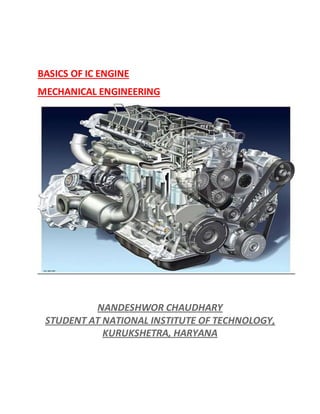
  • 1. BASICS OF IC ENGINE MECHANICAL ENGINEERING NANDESHWOR CHAUDHARY STUDENT AT NATIONAL INSTITUTE OF TECHNOLOGY, KURUKSHETRA, HARYANA
  • 2. IC Engines - Introduction IC Engines Introduction. The engines in which the combustion of fuel takes place insidethe engine cylinder are called internalcombustion engines (briefly written as IC engines). The working pressure and temperature inside the cylinder of an IC engine is very high. The efficiency of IC engines is about 35-40 percent. Two Stroke vs Four Stroke Engines Two Strokevs Four StrokeEngines - Advantages and Disadvantages of Two Stroke over Four StrokeCycle Engines. In a two strokeengine, the working cycle is completed in two strokes of the piston or one revolution of the crankshaft. In a four strokeengine, the working cycleis completed in four strokes of the piston or two revolutions of the crankshaft. The following are the advantages and disadvantages of two strokeover four strokecycle engines: Advantages 1. A two strokecycle engine gives twice the number of power strokes than the four strokecycle engine at the same engine speed. Theoretically, a two strokecycle engine should develop twice the power as that of a four strokecycle engine. 2. For the samepower developed, a two strokecycle engine is lighter, less bulky and occupies less floor area. 3. A two strokecycle engine has a lighter flywheel and gives higher mechanical efficiency than a tour strokecycle engine. Disadvantages 1. The thermal efficiency of a two strokecycle engine is less than that of a four strokecycle engine, because a two strokeengine has less compression ratio than that of a four strokecycle engine. 2. The overall efficiency of a two strokecycle engine is also less than that of a four strokecycleengine. 3. The consumption of lubricating oil is large in a two strokecycle engine becauseof high operating temperature.
  • 3. Sequence of Operations in IC Engine Each strokein ICengines forms a sequenceof operations in one cycle of IC Engines i.e. suction stroke, compression stroke, expansion stroke, and exhaust stroke. Strictly speaking, when an engine is working continuously, wemay consider a cycle starting from any stroke. We know that when the engine returns back to the strokewhereit started, we say that one cycle has completed. The following sequence of operation in a cycle is widely used. 1. Suction stroke. In this stroke, the fuel vapor in correctproportion, is supplied to the engine cylinder. 2. Compression stroke. In this stroke, the fuel vapor is compressed in the engine cylinder. 3. Expansion or working stroke. In this stroke, the fuel vapor is fired just before the compression is complete. Itresults in the sudden riseof pressure, dueto expansion of the combustion products in the engine cylinder. This sudden rise of pressurepushes the piston with a great force and rotates the crankshaft. Thecrankshaft, in turn, drives the machine connected to it. 4. Exhaust stroke. In this stroke, the burntgases (or combustion products) areexhausted fromthe engine cylinder, so as to make space available for the fresh fuel vapor. Valve Timing Diagram of Petrol Engine Valve Timing Diagramfor a Four StrokeCycle Petrol Engine - The petrol engines are also known as spark ignition engines. The valve timing diagramfor a four strokecycle petrol engine is shown in Figure below:
  • 4. The following particulars are importantfor a four strokecycle petrol engine regarding valve timing diagram : (a) The inlet valve opens (IVO) at10° — 20° beforetop dead center (TDC) and closes 30° — 40°after bottom dead center (BDC). (b) The compression of chargestarts at 30° — 40°after BDC and ends at 20° — 30°before TDC. (c) The ignition (IGN) of charge takes place at 20°— 30°before TDC. (d) The expansion starts at 20° — 30° beforeTDC and ends at 30° — 50° before BDC. (e) The exhaust valve opens (EVO) at 30° — 50°before BDC and closes at 10° — 15°after TDC. Notes: (i) The inlet valve of a four strokeI. C. engine remains open for 230°. (ii) The chargeis compressed when both the valves (i.e. inlet valve and exhaust valve) are closed. (iii) The chargeis ignited with the help of a spark plug. (iv) The pressureinsidethe engine cylinder is above the atmospheric pressure during the exhaust stroke.
  • 5. Valve Timing Diagram of Diesel Engine Valve Timing Diagramfor a Four StrokeCycle Diesel Engine - The diesel engines are also known as compression ignition engines. The valve timing diagram for a four strokecycle diesel engine is shown in Figurebelow: The following particulars are importantfor a four strokecycle diesel engine regarding valve timing diagram: (a) The inlet valve opens at 10° — 20°before TDC and closes at 25° — 40°after BDC. (b) The fuel valve opens at 10° — 15° beforeTDC and closes at 15°— 20°after TDC. (c) The compression starts at25° — 40°after BDC and ends at 10°—15° before TDC. (d) The expansion starts at 10° — 15° after TDC and ends at 30° — 50° before BDC. (e) The exhaust valve opens at 30° — 50°before BDC and closes at 10° —15°after TDC. Note:In diesel engines, the fuel is injected in the formof very fine spray into the engine cylinder, which gets ignited due to high temperature of the compressed air.
  • 6. Comparison ofPetrol and Diesel Engines Petrol vs Diesel engines: A comparison - Basic difference between a petrol engine and a diesel engine based on working, pressures, combustion, compression ratios, speed, efficiency, maintenance, and running costs. The following points are important for the comparison of petrol and diesel engines: SN Petrol Engines Diesel Engines 1. A petrol engine draws a mixture of petrol and air during suction stroke. A diesel engine draws only air during suction stroke. 2. The carburetor is employed to mix air and petrol in the required proportion and to supply it to the engine during suction stroke. The injector or atomiser is employed to inject the fuel at the end of compression stroke. 3. The pressure at the end of compression is about 10 bar. The pressure at the end of compression is about 35 bar. 4. The charge (i.e. petrol and air mixture) is ignited with the help of a spark plug. The fuel is injected in the form of fine spray. The temperature of the compressed air (about 600° C at a pressure of about 35 bar) is sufficiently high to ignite the fuel. 5. The combustion of fuel takes place approximately at constant volume. In other words, it works on Otto cycle. The combustion of fuel takes place approximately at constant pressure. In other words, it works on Diesel cycle. 6. A petrol engine has compression ratio approximately from 6 to 10. A diesel engine has compression ratio approximately from 15 to 25. 7. The starting is easy due to low compression ratio. The starting is little difficult due to high compression ratio. 8. As the compression ratio is low, the petrol engines are lighter and cheaper. As the compression ratio is high, the diesel engines are heavier and costlier. 9. The running cost of petrol engines is high because of higher cost of petrol. The running cost of diesel engines is low because of the lower cost of diesel. 10. The maintenance cost is less. The maintenance cost is more. 11. The thermal efficiency is upto about 26%. The thermal efficiency is upto about 40%. 12. Overheating trouble is more due to low thermal efficiency. Overheating trouble is less due to high thermal efficiency. 13. These are high speed engines. These are relatively low speed engines. 14. The petrol engines are generally employed in light duty vehicles such as scooters, motorcycles, cars. These are also used in aero planes. The diesel engines are generally employed in heavy duty vehicles such as buses, trucks and earth moving machines etc.
  • 7. Scavenging of IC Engines The scavenging, in an internal combustion engine (ICEngine), is the process of removing the burntgases fromthe combustion chamber of the engine cylinder. Though there are many types of scavenging, yet the following are important from the subjectpoint of view: 1. Crossflow scavenging. In this method, the transfer port(or inlet portfor the engine cylinder) and exhaustport are situated on the oppositesides of the engine cylinder (as in the caseof two strokecycle engines). 2. Back flow or loop scavenging. In this method, the inlet and outlet ports are situated on the sameside of the engine cylinder. 3. Uniflow scavenging. In this method, the fresh charge, while entering fromone side (or sometimes two sides) of the engine cylinder pushes outthe gases through the exit valvesituated on the top of the cylinder. Note:The scavenging efficiency of a four strokecycle diesel engine is between 95 and 100 percent. Ignition System of Petrol Engines The ignition in a petrol engine takes place by means of a spark plug at the end of the compression stroke. Thevoltage required to producea spark across thegap between the sparking points of a plug is 6000 to 10000 volts. Thefollowing two ignition systems of petrol engines are important: 1. Coil ignition system(also known as battery ignition system); and 2. Magneto ignition system.
  • 8. The coil ignitionsystem has an induction coil, which consists of two coils known as primary and secondary coils wound on a softiron core, as shown in figure above. One end of the primary coil is connected to the ignition switch, ammeter and battery generally of 6 volts. The other end of the primary coil is connected to a condenser and a contact breaker. A condenser is connected across thecontact breaker for the following two reasons: (a) It prevents sparking across thegap between the points, (b) It causes a more rapid break of the primary current, giving a higher voltage in the secondary circuit. The secondary coil is connected to a distributor (in a multi-cylinder engine) with the central terminal of the sparking plugs. Theouter terminals of the sparking plugs are earthed together and connected to the body of the engine. The coil ignition systemis employed in medium and heavy spark ignition engines such as in cars. The magnetoignitionsystem has the sameprinciple of working as that of coil ignition system, except that no battery is required, as the magneto acts as its own generator. This type of ignition systemis generally employed in small spark ignition engines such as scooters, motor cycles and small motor boat engines.
  • 9. Superchargingof IC Engines Supercharging of ICEngines - Itis the process of increasing the mass (or in other words density) of the air fuel mixture (in spark ignition engines) or air (in compression ignition engines) induced into the engine cylinder. This is usually done with the help of a compressor or blower known as supercharger. Ithas been experimentally found that the supercharging increases thepower developed by the engine. Itis widely used in aircraft engines, as the mass of air sucked in the engine cylinder decreases at very high altitudes. This happens, because atmospheric pressuredecreases with the increasein altitude. Following are the objects of supercharging the engines: 1. To reduce mass of the engine per brake power (as required in aircraft engines). 2. To maintain power of air craft engines at high altitudes whereless oxygen is available for combustion. 3. To reduce spaceoccupied by the engine (as required in marine engines). 4. To reduce Consumption of lubricating oil (as required is all types of engines). 5. To increase the power output of an engine when greater power is required (as required in racing cars and other engines). Lubrication of IC Engines The lubrication of ICengines is required to reducetear, vibrations, over heating, and cleaning. The lubrication of ICengines has the following advantages: 1. Itreduces wear and tear of the moving parts. 2. Itdamps down the vibrations of the engine. 3. Itdissipates the heat generated from the- moving parts due to friction. 4. Itcleans the moving parts. 5. Itmakes the piston gas-tight.
  • 10. Governing of IC Engines The process of providing any arrangement, which will keep the engine speed constant(according to the changing load conditions) is known as governing of I.C. engines. Though there are many methods for the governing of I.C. engines, yet the following are important: 1. Hit and miss governing. In this systemof governing, whenever the engine starts running at higher speed (due to decreased load), someexplosions are omitted or missed. This is done with the help of a centrifugal governor. This method of governing is widely used for I. C. engines of smaller capacity or gas engines. 2. Qualitative governing. In this systemof governing, a control valve is fitted in the fuel delivery pipe, which controls the quantity of fuel to be mixed in the charge. The movement of control valve is regulated by the centrifugal governor through rack and pinion arrangement. 3. Quantitative governing. In this systemof goverliing, the quality of charge (i.e. air-fuel ratio of the mixture) is kept constant. But the quantity of mixture supplied to the engine cylinder is varied by means of a throttle valve which is regulated by the centrifugalgovernor through rack and pinion arrangement. 4. Combinationsystemof governing. In this systemof governing, the qualitative and quantitative methods of governing arecombined together. Carburetorof an IC Engine The carburetor is a device for atomising and vaporising the fuel and mixing it with the air in the varying proportions to suit the changing operating conditions of the engine. The process of breaking up and mixing the fuel with the air is called carburetion. * Atomisation is the mechanical breaking up of the liquid fuel into small particles so that every minute particle of the fuel is surrounded by air. ** Vaporization is a changeof state of fuel from a liquid to vapour
  • 11. Spark Plug in IC Engines A spark plug in ICengines is a device used to producespark for igniting the charge of petrol engines. Itis always screwed into the cylinder head. Itis, usually, designed to withstand a pressureupto 35 bar and operate under a current of 10 000 to 30 000 volts. The spark plug gap is kept from0.3 mm to 0.7 mm. Detonation or Knocking in IC Engines Detonation or knocking in I.C. Engines - The loud pulsating noise heard within the engine cylinder of an I.C. engine is known as detonation (also called knocking or inking). Itis caused due to the propagation of a high speed pressurewavecreated by the auto-ignition of end portion of unburntfuel. The blow of this pressure wavemay be of sufficientstrength to break the piston. Thus, the detonation is harmfulto the engine and must be avoided. The following are certain factors which causes detonation: 1. The shape of the combustion chamber, 2. The relative position of the sparking plugs in caseof petrol engines, 3. The chemical nature of the fuel, 4. The initial temperature and pressureof the fuel, and 5. The rate of combustion of that portion of the fuel which is the firstto ignite. This portion of the fuel in heating up, compresses theremaining unburntfuel, thus producing the conditions for auto-ignition to occur. The detonation in petrol engines can be suppressed or reduced by the addition of a small amount of lead ethide or ethyl fluid to the fuel. This is called doping. The following are the chief effects due to detonation: 1. A loud pulsating noisewhich may be accompanied by a vibration of the engine. 2. An increasein the heat lost to the surfaceof the combustion chamber. 3. An increasein carbon deposits.
  • 12. Octane Number - Rating of S.I. Engine Fuels What is OctaneNumber? How rating of SI Engines (Spark ignition engines) is done using an octane number? The hydrocarbon fuels used in spark ignition (S.I.) enginehave a tendency to causeengine knock when the engine operating conditions become severe. The knocking tendency of a fuel in S. I. engines is generally expressed by its octane number. The percentage, by volume, of iso-octanein a mixture of iso-octane and normal heptane, which exactly matches the knocking intensity of a given fuel, in a standard engine, under given standard operating conditions, is termed as the octane number rating of that fuel. Thus, if a mixture of 50 percent iso-octane and 50 percent normal heptane matches the fuel under test, then this fuel is assigned an octane number rating of 50. If a fuel matches in knocking intensity a mixture of 75 percent iso-octane and 25 percent normalheptane, then this fuel would be assigned an octane number rating of 75. This octane number rating is an expression which indicates the ability of a fuel to resistknock in a spark ignition engine. Since iso-octane is a very good anti-knock fuel, thereforeit is assigned a rating of 100 octane number. On the other hand, normal heptane has a very poor anti- knock qualities, therefore, it is given a rating of zero octane number. These two fuels, i.e., iso-octane and normal heptane are known as primary reference fuels. It may be noted that higher the octane number rating of a fuel, the greater will be its resistanceto knock and higher will be the compression ratio. Since the power output and specific fuel consumption are functions of compression ratio, therefore we may say that these are also functions of octane number rating. This fact indicates the extreme importanceof the octane number rating in fuels for S. I. engines. Note:The octane number of petrol, generally available, is 80 to 100. Cetane Number - Rating of CI Engine Fuels What is Cetane Number? How rating of fuels used in C. I. Engines (Compression Ignition Engines) is done using Cetane number and other parameters? The knocking tendency is also found in compression ignition (C. I.) engines with an
  • 13. effect similar to that of S. I. engines, but it is due to a different phenomenon. The knock in C. I. engines is due to sudden ignition and abnormally rapid combustion of accumulated fuel in the combustion chamber. Such a situation occurs because of an ignition lag in the combustion of the fuel between the time of injection and the actual burning. The property of ignition lag is generally measured in terms of cetane number. Itis defined as the percentage, by volume, of cetane in a mixture of cetane and alpha- methyl-naphthalene that produces the sameignition lag as the fuel being tested, in the same engine and under the same operating conditions. For example, a fuel of cetane number 50 has the same ignition quality as a mixture of 50 percent cetane and 50 percent alpha-methyl-naphthalene. The cetane which is a straightchain paraffin with good ignition quality is assigned a cetane number of 100 and alpha methyl-naphthalene which is a hydrocarbon with poor ignition quality, is assigned a zero cetane number. Notes: 1. The knocking in C. I. engines may be controlled by decreasing ignition lag. The shorter the ignition lag, the lesser is the tendency to knock. 2. The cetane number of diesel oil, generally available, is 40 to 55 Testing of IC Engines Testing of ICEngines - why is it done? The purposeof testing an internal combustion engine (ICEngine) are (a) To determine the information which cannot be obtained by calculations. (b) To conformthe data used in design, the validity of which is doubtful. (c) To satisfy the customer regarding the performanceof the engine. An internal combustion engine (ICEngine) is put to thermodynamic tests, so as to determine efficiency and performanceindicators
  • 14. ThermodynamicTests for I.C. Engines Why thermodynamic tests are done on ICEngines? An internal combustion engine (ICEngine) is put to thermodynamic tests, so as to determine the following quantities: Indicated mean effective pressure Indicated power of an ICEngine Brake power of IC Engine Efficiency of an ICEngine Indicated mean effective pressure The indicated mean effective pressureof an ICengine is obtained fromthe indicator diagramdrawn with the help of an engine indicator. Mathematically, mean effective pressure(in bar) Itmay be noted that the mean effective pressurecalculated on the basis of theoretical indicator diagram, is known as theoretical mean effective pressure. If it is based on the actual indicator diagram, then it is called actual mean effective pressure. Indicated power of an IC Engine The indicated power of an ICengine (briefly written as I.P.) is the power actually developed by the engine cylinder. Mathematically, Where K = Number of cylinders,
  • 15. pm = Actual mean effective pressurein bar (1 bar = 100 kN/m2), L = Length of strokein meters, A = Area of the piston in m2, n = Number of working strokes per minute = Speed of the engine for two strokecycle engine = Half the speed of the engine for four strokecycle engine. Note: The I.P. of a multi-cylinder of spark ignition engineis determined by Morse test. Brake power of IC Engine The brake power (briefly written as B.P.) of an ICEngine is the power available at the crankshaft. Thebrakepower of an I.C. engine is, usually, measured by means of a brakemechanism (prony brakeor ropebrake). In caseof prony brake, brakepower of the engine, Where W = Brake load in newtons, l = Length of arm in metres, and N = Speed of the engine in r.p.m. In caseof rope brake, brakepower of the engine, Where W = Dead load in newtons,
  • 16. S = Spring balance reading in newtons, D = Diameter of the brakedrumin metres, d = Diameter of the rope in metres, and N = Speed of the engine in r.p.m. Note: The brakepower (B.P.) of an engine is always less than the indicated power (I.P.) of an engine, because somepower is lost in overcoming the engine friction (known as frictional power). Mathematically, Frictional power, F.P. = I.P. —B.P. Efficiency of an IC Engine The efficiency of an ICengine (InternalCombustion Engine) is defined as the ratio of work doneto the energy supplied to an engine. The following efficiencies of an 1.C. engine are important: (a) Mechanical efficiency. Itis theratio of brake power (B.P.) to the indicated power (I.P.). Mathematically, mechanical efficiency, Since B. P. is always less than I.P., thereforemechanicalefficiency is always less than unity (i.e. 100%). (b) Overall efficiency. Itis the ratio of the work obtained at the crankshaftin a given time to the energy supplied by the fuel during the same time. Mathematically, overall efficiency, Where
  • 17. B.P. = Brake power in kW, mf = Mass of fuel consumed in kg per hour, and C = Calorific valveof fuel in kJ / kg of fuel. (c) Indicatedthermal efficiency. Itis the ratio of the heat equivalent to one kW hour to the heat in the fuel per I.P. hour, mathematically, indicated thermal efficiency, Note: The following ratio is known as specific fuel consumption per I.P. hour: (d) Brake thermal efficiency. Itis the ratio of the heat equivalent to one kW hour to the heat in the fuel per B.P. hour. Mathematically, brake thermal efficiency, Note: The following ratio is known as specific fuel consumption per B. P. hour: (e) Air standardefficiency. Thegeneral expression for the air standard efficiency is given as (For petrol engines) (For diesel engines) (f) Relative efficiency. Itis also known as efficiency ratio. The relative efficiency of
  • 18. an I. C. engine is the ratio of the indicated thermal efficiency to the air standard efficiency. (g) Volumetric efficiency. Itis the ratio of the actual volumeof charge admitted during the suction strokeat N.T.P to the sweptvolume of the piston.