Iai linear servo_actuator_catalog
•
1 like•525 views

1) The document describes a lineup of linear servo actuators sold by Electromate for small to large systems. It provides details on various actuator models ranging from compact shaft types to large types that can transfer loads of up to 120kg. 2) The actuators can be controlled using three types of controllers to support different control modes and up to six axes simultaneously. Accessories like motor cables, encoder cables and regenerative resistance units are also described. 3) Specification tables provide the technical details of each actuator model like stroke lengths, thrusts, speeds and payload capacities to help customers select the suitable model for their application.

More Related Content
What's hot
What's hot (20)
Similar to Iai linear servo_actuator_catalog
Similar to Iai linear servo_actuator_catalog (20)
More from Electromate
More from Electromate (20)
Recently uploaded
Recently uploaded (20)
Iai linear servo_actuator_catalog
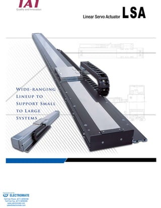
- 1. Wide-ranging Lineup to Support Small to Large Systems Linear Servo Actuator Sold & Serviced By: ELECTROMATE Toll Free Phone (877) SERVO98 Toll Free Fax (877) SERV099 www.electromate.com sales@electromate.com
- 2. A Full Lineup of Models Meeting Maximum speed of 2,500 mm/sec, maximum acceleration/ deceleration of 3 G, maximum payload of 120 kg, and maximum stroke of 4 m. ● Compact, lightweight shaft type ● Small type with flat motor achieving high thrust with a slim body ● Flat type ideal for vertically confined space ● Medium type boasting high moment rigidity ● Large type capable of transferring a maximum load of 120 kg over 4 m Shaft type 1 Shaft type Shaft type Small type Flat type Medium type Large type Sold & Serviced By: ELECTROMATE Toll Free Phone (877) SERVO98 Toll Free Fax (877) SERV099 www.electromate.com sales@electromate.com
- 3. Meeting Various Applications Select from three types of controllers. Controllers supporting three different control modes—positioner, pulse-train and program—are available. A new multi-slider collision prevention function has been added to the SSEL/XSEL controller series. 2 1-axis/2-axis program controller achieving high cost performance 1-axis controller capable of operating actuators in the positioner mode and pulse-train mode High-performance program controller capable of controlling up to six axes at the same time NEW NEW Sold & Serviced By: ELECTROMATE Toll Free Phone (877) SERVO98 Toll Free Fax (877) SERV099 www.electromate.com sales@electromate.com
- 4. Features Performance/Functions Capable of Transferring a Payload of Up to 120 kg over a Length of Up to 4.15 m Despite its compact body, the large type (W21 type) generates a high rated thrust of 400 N through its unique structure that adopts a high-density coil with core and flat magnet. This high thrust enables the actuator to accommodate a payload of up to 120 kg. The W21 can also be ordered with a long stroke of up to 4.15 m, which is ideal for transferring large LCD boards. Significant Reduction in Cycle Time with a High Acceleration of Up to 3 G and High Speed of 2.5 m/sec The high performance backed by the maximum acceleration of 3 G and maximum speed of 2.5 m/sec reduces the cycle time significantly compared to when single-axis robots of ball-screw type are used. Unlike with ball-screw actuators, linear servo actuators will not suffer from a drop in their maximum speed as a result of reaching a dangerous speed, even when operated over a long stroke. This means that loads can be transferred reliably at high speed. Multi-slider Type and Synchronization Function We have a line of multi-slider models that allow multiple sliders to be operated on a single actuator. These configurations are very effective in saving space and reducing the cycle time. Also, you can use the synchronization function - a popular function offered by the XSEL controller series - to configure a system for transferring glass boards whose size is increasing, or transferring a load at high speed over a wide range. A Wide-ranging Lineup Supporting Small to Large Systems Our linear servo actuators are classified into the small, lightweight shaft type, small type with a slim body, flat type with low height, intermediate type offering excellent moment rigidity, and large type capable of transferring a maximum load of 120 kg, among others. We provide a wide selection for you to choose from according to your specific application. Compact, Low-cost Shaft Type The shaft has a built-in magnet surrounded by a coil to utilize magnetic flux in all directions. As a result, even the compact actuator can generate high thrust. Since the structure requires fewer magnets, the shaft type also offers a great cost advantage. Large, High-thrust Type for High-load Applications The large, high-thrust type adopts a roller-guide structure to support high loads of up to 120 kg. Since the roller guide is less subject to elastic deformation due to load compared to the ball guide, the operation is quiet and smooth while high moment rigidity is also ensured. Comparison of Traveling Time between Linear Servo Actuator and Single-axis Robot ■ Comparison conditions Travel: 1 m Move at the maximum speed. 0.15 sec of settling time is included. Multi-slider type Synchronized operation Section View of Large Type Variations/Structures 3 2500 2000 1500 1000 500 0.64 Rated speed: 1000mm/s Rated speed: 2,500 mm/sec Acceleration: 3 G Acceleration: 1 G Time (sec) Speed (mm/sec) 1.25 Single-axis robot Linear servo actuator Coil unit Linear scale Cable track Guide Magnet Sold & Serviced By: ELECTROMATE Toll Free Phone (877) SERVO98 Toll Free Fax (877) SERV099 www.electromate.com sales@electromate.com
- 5. Test stopped after 1,800 km due to significant wear Linear scale No problem for 25,000 km Distance traveled (km) Coil unit Magnet shaft Guide Base Maintainability/Low Cost AQ Seals Achieving Maintenance-free Operation for a Long Time With linear servo motors, the magnet is not contacting the coil, which means these motors do not need maintenance. Also, all shaft models come with AQ seals installed on their guide. AQ seals supply lubricating oil to the guide over a long period, so the guide need not be oiled for years. A majority of parts and components comprising IAI’s linear servo actuators, such as the base, guide, linear motor and linear scale, have been developed internally by IAI. Use of in-house parts and components means that the costs of these actuators are kept to a minimum. ■ Traveling Test Data (with/without AQ Seals) With AQ seals ■ Section View of Shaft Type Low Cost Controller Program/Positioner Control Program Control of Up to 6 Axes A high-function, multi-axis controller capable of controlling up to six axes simultaneously. You can also control a combination of linear servo actuators and single-axis robots using the X-SEL. Easy Control Multi-slider Collision Prevention Function Positioner/Pulse-train Control A dedicated single-axis controller offering both the positioner function and pulse-train input function. Low price is also an attractive feature of the SCON controller. A program controller capable of controlling up to two axes using a simple program (SEL language). The SSEL controller can be used standalone without any external device (PLC). You can also switch to the positioner mode to use the SSEL as a positioner controller. 4 No lubrication Just like single-axis robots and motorized cylinders, operation of IAI’s linear servo actuators is very easy. All you need is to connect the actuator to a controller using a dedicated cable and supply the power. The actuator is now ready to go without cumbersome settings or adjustments. You can also select a desired controller from three different types according to your specific application. A new function has been added to prevent two sliders from colliding with each other when operated independently in the multi-slider operation mode. Sold & Serviced By: ELECTROMATE Toll Free Phone (877) SERVO98 Toll Free Fax (877) SERV099 www.electromate.com sales@electromate.com
- 6. ■ List of Actuator Specifications 5 Exterior view Slider Stroke (mm) Thrust (N) Maximum speed (mm/sec) Model (type) Pages Maximum payload (kg) Actuator width (mm) S6SS P15~16 60 15 P17~18 P19~20 P21~22 P23~24 P25~26 P27~28 P29~30 P31~32 P33~34 P35~36 P37~38 P39~40 P41~42 P43 P44 P45 P46 P47 P48 P49 P50 S6SM S8SS S8SM S8HS S8HM S10SS S10SM S10HS S10HM H8SS H8SM H8HS H8HM L15SS L15SM N19SS N19SM W21SS W21SM W21HS W21HM 3 5 7 15 20 5 2500 8 5 30 60 120 25 35 65 80 30 60 30 100 200 400 Single-slider 48~1248 40~1048 60~1620 60~1440 60~1620 60~1380 90~2070 60~1860 90~2070 105~1815 50~1650 130~1430 50~1550 130~1230 150~1650 50~1450 144~2592 72~2232 1050~4155 730~3835 895~4000 420~3525 80 100 80 145 193 210 Shaft type Small type Flat type Medium type Large type Standard Standard High thrust Standard High thrust Standard High thrust Standard Standard Standard High thrust Multi-slider Single-slider Multi-slider Single-slider Multi-slider Single-slider Multi-slider Single-slider Multi-slider Single-slider Multi-slider Single-slider Multi-slider Single-slider Multi-slider Single-slider Multi-slider Single-slider Multi-slider Single-slider Multi-slider Sold & Serviced By: ELECTROMATE Toll Free Phone (877) SERVO98 Toll Free Fax (877) SERV099 www.electromate.com sales@electromate.com
- 7. ■ List of Controller Specifications 6 Shaft Type Small Type Flat Type Exterior view Medium Type Large Type (Standard) Large Type (High thrust) Single-axis robot Number of controlled axes Model (series – type) Pages Number of positions Input power supply Number of programs 1 axis − 1 axis 2 axes 512 128 programs 9999 steps Single-phase AC100V AC200V 1 axis 2 axes 3 axes 4 axes 5 axes 6 axes Feature Affordable 1-axis positioner capable of both positioner control and pulse-train control Also supporting field network connection Affordable 2-axis controller that can perform interpolation operation via program control High-function, multi-axis controller capable of operating up to six axes simultaneously Also supporting field network connection Single-phase 128 programs AC200V 9999 steps 20,000 Three-phase AC200V SCON-C XSEL-P XSEL-Q P51 20,000 SSEL-C P52 P53 ■ Correspondence Table of Actuator/Controller Operation SCON−C SSEL−C ○ ○ ○ ○ ○ ○ ○ ○ ○ ○ × × ○ ○ XSEL−P/Q ○ ○ ○ ○ ○ ○ ○ Controllers Actuators Sold & Serviced By: ELECTROMATE Toll Free Phone (877) SERVO98 Toll Free Fax (877) SERV099 www.electromate.com sales@electromate.com
- 8. ■ System Configuration SCON Controller 7 PLC Teaching pendant (Refer to P. 62.) <Model: RCM-T/TD> <Model: RCM-E> <Model: RCM-P> * Take note that network-ready SCON controllers do not support pulse-train control. Field network I/O flat cable (Refer to P. 66.) <Model: CB-PAC-PIO□□□> Cable length: 2 m (standard) (Supplied with the controller) To connect an SCON controller to a field network, you can either select a network-ready model or use a gateway unit. Network-ready SCON models can be connected directly to a network. However, their functions will be limited to the remote I/O level (= control will be solely based on ON/OFF of I/Os). If a gateway unit is used, you can have numerical data such as coordinate values communicated between the controller and actuator. Regenerative resistance unit (Refer to P. 64.) Model: REU-2 (Optional) (Manufacturer: Densei-Lambda) (You can also purchase the above noise filter through IAI. Please contact IAI for details.) Motor cable (Refer to P. 65.) Model: CB-X-MA□□□ (For Shaft, Small, Flat and Medium Types) Model: CB-XMC-MA□□□ (For Large type) If command pulse trains of open collector method are used, be sure to use a pulse converter. Plug + shell for pulse-train input (Supplied with the controller) * Communication cable for pulse-train input (Refer to P. 66.) <Model: CB-SC-PIOS□□□> (Optional) ① External device communication cable Model: CB-RCA-SIO050 ② RS232 conversion adapter Model: RCB-CV-MW ③ USB conversion adapter Model: RCB-CV-USB ④ USB cable Model: CB-SEL-USB010 Encoder cable (Refer to P. 65.) Model: CB-X2-PA□□□ (For Shaft, Small, Flat and Medium Types) Model: CB-X2-PLA□□□ (For Large type) Absolute-data backup battery (Refer to P. 64.) Model: AB-5 5m 5m BIGIN END 1 2 3 PC software (Refer to P. 62.) RS232 connection type (Comes with ① and ②) <Model: RCM-101-MW> PC software (Refer to P. 62.) USB connection type (Comes with ①, ③ and ④) <Model: RCM-101-USB> Main power supply Single-phase AC100V Single-phase AC200V Be sure to use a noise filter w hen Recommended model MC1210 connecting to a power supply. ESC 7 8 9 4 5 6 0 IAI 5m 1m * * The cable is supplied with the PC software. Refer to P. 64 for details on replacement cables. * Sold & Serviced By: ELECTROMATE Toll Free Phone (877) SERVO98 Toll Free Fax (877) SERV099 www.electromate.com sales@electromate.com
- 9. ■ System Configuration 8 SSEL Controller 0.2m PC software (Refer to P. 63.) Model: IA-101-X-MW (with RS232C cable) IA-101-X-USB (with USB cable) (Optional) System-memory backup battery (Refer to P. 64.) Model: AB-5-CS (with case) XSEL Controller PLC Teaching pendant (Refer to P. 63.) Model: IA-T-X/XD/XA (Optional) I/O flat cable (Refer to P. 66.) Model: CB-DS-PIO020 (Supplied with the controller) Main power supply Single-phase AC200V/Three-phase AC200V Panel unit (Refer to P. 64.) Model: PU-1 (Optional) Regenerative resistance unit cable Model: CB-SC-REU010 Motor cable (Refer to P. 65.) Model: CB-X-MA□□□ (For Shaft, Small, Flat and Medium Types) CB-XMC-MA□□□ (For Large type) Absolute-data backup battery (Refer to P. 64.) Model: AB-5 AB-5 (battery only) (Optional) *1 USB cable (Refer to P. 64.) Model: CB-SEL-USB010 (Supplied with PC software IA-101-X-USB) RS232C cable Model: CB-ST-E1MW050- EB (Supplied with PC software IA-101-X-MW) Conversion cable (Refer to P. 64) Model: CB-SEL-SJ002 (Optional) 2m PLC I/O flat cable (Refer to P. 66.) Model: CB-X-PIO020 (Supplied with the controller) 2m 4m 5m 1m 5m 1m 1m 3m Main power supply Single-phase AC100V 1m 4m 5m • DeviceNet • CC-Link • ProfiBus • Ethernet *1 The system-memory backup battery is required if you want to retain flags and other data used in the program even after the power is turned off. ① RS232C cable Model: CB-ST-E1MW050-EB ② USB conversion unit (Refer to P. 64.) Model: IA-CV-USB ③ USB cable (Refer to P. 64.) Model: CB-SEL-USB010 PC software (Refer to P. 63.) Model: IA-101-X-MW (Comes with ①) IA-101-X-USBMW (Comes with ①, ② and ③) (Optional) Be sure to use a noise filter when connecting to a power supply. * Single-phase AC200V Recommended model MC1220 (100V) MC1210 (200V) (Manufacturer: Densei-Lambda) (You can also purchase the above noise filter through IAI. Please contact IAI for details.) Encoder cable (Refer to P. 65.) Model: CB-X2-PA□□□ (For Shaft, Small, Flat and Medium Types) Model: CB-X2-PLA□□□ (For Large type) Teaching pendant (Refer to P. 63.) Model: IA-T-X/XD/XA (Optional) Regenerative resistance unit (Refer to P. 64.) Model: REU-2 (Optional) Regenerative resistance unit (Refer to P. 64.) Model: REU-1 (Optional) Regenerative resistance unit cable Model: CB-SC-REU010 Absolute-data backup battery (Refer to P. 64.) Model: AB-5 Motor cable (Refer to P. 65.) Model: CB-X-MA□□□ (For Shaft, Small, Flat and Medium Types) CB-XMC-MA□□□ (For Large type) Encoder cable (Refer to P. 65.) Model: CB-X2-PA□□□ (For Shaft, Small, Flat and Medium Types) Model: CB-X2-PLA□□□ (For Large type) Sold & Serviced By: ELECTROMATE Toll Free Phone (877) SERVO98 Toll Free Fax (877) SERV099 www.electromate.com sales@electromate.com
- 10. 9 ■ Examples of Use Loader/Unloader By using a multi-slider type, you can perform with one actuator what normally requires two actuators. This saves both space and cost. Transfer of Parts between Processes Boasting the maximum acceleration of 3 G and maximum speed of 2.5 m/sec, linear servo actuators can certainly reduce your cycle time. Glass Board Transfer System By synchronizing two large actuators each capable of transferring a load of up to 120 kg, you can also transfer large glass boards. Glass Board Inspection System A combination of a large linear servo actuator with the maximum stroke of 4,155 mm, with a small linear servo actuator, allows for high-speed inspection over a wide range. Sold & Serviced By: ELECTROMATE Toll Free Phone (877) SERVO98 Toll Free Fax (877) SERV099 www.electromate.com sales@electromate.com
- 11. ■ Model Selection When selecting an appropriate linear servo actuator, remember that your actuator must meet the following two conditions. • The thrust required for acceleration is equal to or less than the maximum thrust Selection method V ta tf t td tc T F Fa Ff Fd ta tf t td T 10 of the linear servo actuator. • The thrust during continuous operation is equal to or less than the rated thrust of the linear servo actuator. The above conditions are explained using the trapezoid operation pattern as an example. The operation pattern shown to the left can be converted to the graph below where the vertical axis represents thrust: In the above graph: t : Operation time per cycle (sec) tf : Time traveled at constant speed (sec) ta: Acceleration time (sec) td: Deceleration time (sec) tc: Settling time (sec) In the above graph: Fa: Thrust required for acceleration (N) Fd: Thrust required for deceleration (N) Ff: Traveling resistance (N) Thrust required for acceleration (Fa) ≦ Maximum thrust of linear servo actuator If the thrust required for acceleration (Fa) exceeds the maximum thrust of the linear servo actuator, the slider load or acceleration must be reduced. Check the maximum payload and maximum acceleration using the following formulas, respectively: Maximum payload m = (Fa - Ff) / a - M Maximum acceleration a = (Fa - Ff) / (M + m) For the slider to accelerate according to the command, the thrust required for acceleration, or Fa, must be smaller than the maximum thrust of the linear servo actuator. Calculate the thrust required for acceleration (Fa) using the formula below: S6SS S8SS S8HS S10SS S10HS H8SS H8HS L15SS N19SS W21SS W21HS Weight of slider (kg) Traveling resistance Maximum thrust (N) 1.4 1.7 2.0 3.5 4.0 1.5 2.0 1.5 5.5 10.0 20.0 5V + 5 9V + 7 9V + 7 20V + 13.5 20V + 13.5 2V + 10 2V + 10 2V + 10 16V + 12 20V + 70 20V + 70 60 100 140 260 320 90 180 90 Refer to the graph on the right. 600 1200 Ff (N) * V: Slider traveling speed (m/sec) (The attained speed is used under the triangle operating condition.) 350 300 250 200 150 100 50 0 263 225 188 0 500 1000 1500 2000 2500 Slider traveling speed (mm/sec) Fa = (M+m) • a+Ff M : Weight of slider (kg) m : Slider load (kg) a : Command acceleration (m/sec²) Ff : Traveling resistance (N) Maximum thrust of N19SS Condition Maximum Thrust Motor generated output (N) If the obtained value of Fa is smaller than the maximum thrust of the linear servo actuator, condition ① is satisfied. Sold & Serviced By: ELECTROMATE Toll Free Phone (877) SERVO98 Toll Free Fax (877) SERV099 www.electromate.com sales@electromate.com
- 12. After considering the load and duty, the thrust during continuous operation, or Ft, must be smaller than the rated thrust of the linear servo actuator. Calculate the thrust during continuous operation using the formula below: Triangle pattern Speed Time sec mm/s Fa • ta + Ff • tf + Fd • td Acceleration zone Constant speed zone Deceleration zone Positioning settling time Positioning time Speed mm/s Ft = t Thrust during continuous operation (Ft) ≤ Rated thrust of linear servo actuator ■ tf represents the time traveled at constant speed. Calculate tf by calculating the distance traveled at constant speed, as follows: tf = Lc/V Lc : Time traveled at constant speed (m) V : Command speed (m/sec) ■ Fd represents the thrust required for deceleration. Calculate Fd using the formula below: Fd = (M + m) • a – Ff ■ td represents the deceleration time. If the acceleration is the same as the deceleration, td should be the same as the acceleration time. ■ t represents the operation time per cycle and is calculated as a total sum of the acceleration time (ta), constant speed time (tf), deceleration time (td), settling time (refer to the table below), and stationary time. 15 25 35 65 80 Models Settling time Fa • ta + Ff • tf + Fd • td S6SS S8SS S8HS S10SS S10HS Rated thrust (N) Rated thrust (N) H8SS H8HS L15SS N19SS W21SS W21HS 30 60 30 100 200 400 t = Ft Whether a given operation pattern is trapezoid or triangle can be determined by whether the speed attained by the actuator when operated over the specified travel at the specified speed is greater or smaller than the specified speed. Attained speed (Vmax) = Travel (m) x Specified acceleration (m/sec²) * Distance traveled at constant speed = Travel – Acceleration distance – Deceleration distance Acceleration distance (deceleration distance) = V²/2a td = V/a V : Speed (m/sec) a : Acceleration (m/sec²) S6SS, S6SM, H8SS, H8SM, H8HS, H8HM, W21SS, W21SM, W21HS, W21HM S8SS, S8SM, S8HS, S8HM, S10SS, S10SM, S10HS, S10HM, N19SS, N19SM 0.15s 0.2s Condition Thrust during Continuous Operation Fa: Thrust required for acceleration (N) ta: Acceleration time (sec) Ff: Traveling resistance (N) tf: Rated traveling time (sec) Fd: Thrust required for deceleration (N) td: Deceleration time (s) t: Operation time per cycle (sec) (t = ta + tf + td + settling time + stationary time) ta represents the acceleration time. Here, how to calculate ta varies depending on whether the actuator is operated in the trapezoid pattern or triangle pattern. Specified speed < Attained speed Trapezoid pattern Specified speed Attained speed Triangle pattern Trapezoid pattern Specified speed (m/sec) Command acceleration (m/sec²) Specified speed (m/sec) Command acceleration (m/sec²) Trapezoid pattern Triangle pattern Positioning settling time Time Acceleration sec zone Deceleration zone Positioning time If the thrust during continuous operation (Ft) obtained as above is smaller than the rated thrust, condition is satisfied. If you want to use the maximum acceleration obtained in the test of condition to calculate the cycle time that allows for continuous operation, check if the calculated result is viable using the formula below: The actuator can be operated under conditions where both conditions and above are satisfied. If either condition is not satisfied, reduce the slider load, acceleration or duty (*) or take other appropriate measures. * To reduce the duty, the ratio of traveling time (acceleration + constant speed + deceleration) to cycle time must be lowered. 11 ELECTROMATE Sold Serviced By: Toll Free Phone (877) SERVO98 Toll Free Fax (877) SERV099 www.electromate.com sales@electromate.com
- 13. Exercise same time. 12 Let’s select a linear servo actuator using the selection method explained in the preceding section. ★ Operating conditions ● Actuator model LSA-H8SS ● Speed 2.5m/sec ● Acceleration 19.6m/sec (The deceleration is *1G = 9.8m/s assumed to be the same.) ● Travel distance 1.5m ● Slider load 3kg ● Settling time 0.15sec ● Stroke 1.5 m The actuator will move back and forth under the above conditions. The above operation pattern is illustrated by the graph shown to the right. Now, let’s start calculation according to the selection method. Condition Calculate the maximum thrust Apply the above operation pattern to the formula for maximum thrust explained earlier: Fa = (M + m) • a + Ff Condition Calculate the thrust during Ft = continuous operation Fa • ta + Ff • tf + Fd • td t Now, when the operation pattern at ta is checked, the following is revealed: Attained speed (Vmax) = 1.5×16.6 → 4.9 m/sec Since this value is greater than the specified speed of 2.5 m/sec, the operation pattern is determined to be trapezoid. Accordingly, ta = 2.5÷1.6 → 0.15s V ta tf t td T Next, tf is calculated. Distance traveled at constant speed = 1.5 - {(2.5×2.5) ÷ (2×16.6)} × 2 → 1.12m tf = 1.12 ÷ 2.5 → 0.45s Thrust required for deceleration Fd = (1.5+3) × 16.6 - 15 → 59.7N Since td = ta, t = ta + tf + td + 0.15 → 0.9 sec. When the above values are applied, the earlier formula is rephrased as follows: Ft = {(89.7 × 89.7) × 0.15 + (15 × 15) × 0.45 + (59.7 × 59.7) × 0.15} ÷ 0.9 → 45.25N Since the result exceeds the rated thrust of the H8SS, or 30 N, this actuator cannot be used in this operation pattern. Now, let’s calculate the cycle time that allows for continuous operation: t = {(89.7 × 89.7) × 0.15 + (15 × 15) × 0.45 + (59.7 × 59.7) × 0.15} ÷ (30 × 30) → 2.05s As evident from the result, continuous operation can be performed if the cycle time is increased from 0.9 sec to 2.05 sec. So, let’s recalculate by assuming t = 2.05. V ta tf t = 2.05 td T Ft = {(89.7 × 89.7) × 0.15 + (15 × 15) × 0.45 + (59.7 × 59.7) × 0.15} ÷ 2.05 → 30N Now, the actuator can be operated. Where, M : Weight of slider (kg): 1.5 kg for the H8SS m : Slider load (kg): 3 kg is used in this exercise. a : Command acceleration (m/sec²) : 19.6 m/sec² is used in this exercise. Ff : Traveling resistance: 15 N is used in this exercise. Based on the above conditions, the formula is rephrased as follows: Fa = 4.5×19.6 + 15 → 103.2N Since the maximum thrust of the H8SS is 90 N, this actuator cannot be used under these conditions. Accordingly, either the slider load or acceleration must be changed. If the slider load is to be changed without changing the acceleration, the maximum load is calculated as follows: m = (90 - 15) ÷19.6 - 1.5 → 2.32 kg If the acceleration is to be changed without changing the slider load (3 kg), the maximum acceleration is calculated as follows: a = (90 - 15) ÷ (1.5 + 3) → Approx. 16.6m/s² In this exercise, the acceleration is changed to 16.6 m/sec². Fa = 4.5 × 16.6 + 15 → 89.7N 90N (maximum thrust) Apply the above operation pattern to the formula for thrust during continuous operation explained earlier. For your reference, the command acceleration is assumed to be 16.6 m/sec² based on the examination result of maximum thrust: Sold Serviced By: ELECTROMATE Toll Free Phone (877) SERVO98 Toll Free Fax (877) SERV099 www.electromate.com sales@electromate.com
- 14. S8HS ① Series ② Type Indicate ③ Encoder type ④ Applicable driver output ⑤ Stroke ⑥ Applicable controller ⑦ Cable length ⑧ Options 13 the name of each series. No cable 3mm 5mm Specified length Robot cable 48 ~ 48mm ~ 4000mm Indicate the type, actuator width, motor type and slider type. Example) S 10 S M Type S: Shaft Type H: Small Type L: Flat Type N: Medium Type W: Large Type Actuator width 6:60mm 8:80mm 10:100mm 15:145mm 19:193mm 21:210mm Motor type S: Standard type / H: High-thrust type Slider type S: Single-slider type / M: Multi-slider type Indicate the type of the encoder installed in the actuator. I: Incremental type Since the slider position data is lost every time the power is turned off, home return must be performed every time the power is turned on. Indicate the driver wattage of the controller to be connected. Indicate the stroke (range of operation) of the actuator (unit: mm). Indicate the types of controllers with which the actuator can be operated. T2: SCON/SSEL/XSEL - P/Q Indicate the length of the motor/encoder cable connecting the actuator and controller. N: No Cable * The maximum cable S: 3m length is 20 m for the SCON/SSEL and 30 m M: 5m for the XSEL. X□□: Select this option if you want to specify a length other than 1, 3 and 5 m (Example: X08 = 8 m) (*) The standard cables are robot cables. Indicate the options to be installed on the actuator. Refer to the facing page for details on CT2 to UM6. * With the large type, the limit switch is a standard feature (required option). However, you must still specify “L” in the model name. N S M X□□ R□□ S6SS S6SM S8SS S8SM S8HM S10SS S10SM S10HS S10HM H8SS H8SM H8HS H8HM L15SS L15SM N19SS N19SM W21SS W21SM W21HS W21HM Single-slider, 60 mm wide Multi-slider, 60 mm wide Single-slider, 80 mm wide Multi-slider, 80 mm wide High-thrust single slider, 80 mm wide High-thrust multi-slider, 80 mm wide Single-slider, 100 mm wide Multi-slider, 100 mm wide High-thrust single slider, 100 mm wide High-thrust multi-slider, 100 mm wide Single-slider, 80 mm wide Multi-slider, 80 mm wide High-thrust single slider, 80 mm wide High-thrust multi-slider, 80 mm wide Single-slider, 145 mm wide Multi-slider, 145 mm wide Single-slider, 193 mm wide Multi-slider, 193 mm wide Single-slider, 210 mm wide Multi-slider, 210 mm wide High-thrust single slider, 210 mm wide High-thrust multi-slider, 210 mm wide I Incremental 4000 The stroke varies depending on the model. Selected cable track model ■ Model T2 Shaft Type Small Type Flat Type Medium Type Large Type CT2 CT3 CT4 CT5 CT6 US1 US2 US3 US4 US5 US6 UM1 UM2 UM3 UM4 UM5 UM6 L (Standard) Limit switch 100 100W 200W 300W 400W 1000W 200 300 400 1000 * Refer to the models specified under “Cable Track Options” on P. 14. LSA I Series Type Encoder type Applicable driver output Stroke Applicable controller Cable Options Sold Serviced By: ELECTROMATE Toll Free Phone (877) SERVO98 Toll Free Fax (877) SERV099 www.electromate.com sales@electromate.com
- 15. 14 ■ Cable Track Options The cable track that comes standard with the shaft type and small type is designed exclusively for wiring a linear servo actuator and provides no space for additional cables the customer may require. If you must wire additional cables, specify a cable track for user wiring by selecting an appropriate model from the right. Cable tracks are available in two sizes of S and M, and you can select the installation direction from the six types illustrated below. * Although cable tracks for user wiring are not available for the flat type, medium type and large type, you can still specify a desired installation direction for the standard cable track (excluding the sideway specification.) 【Cable Track for User Wiring】 Cable track for user wiring 14 15 60 【Installation direction】 【Model】 Model direction CT2 CT3 CT4 CT5 CT6 US1 US2 US3 US4 US5 US6 UM1 UM2 UM3 UM4 UM5 UM6 Cable track for user wiring Installation None Type S Type M 1 (Standard) 2 3 4 5 6 1 2 3 4 5 6 1 2 3 4 5 6 Cable track direction 1 (standard) Cable track direction 2 (opposite): CT2 Cable track direction 3 CT3 This is the standard installation direction that applies when a cable track direction is not specified. With a single-slider model, the cable track is installed in the direction shown below. With a multi-slider model, one cable track is installed on both ends. Cable track direction 5 (sideway, standard): CT5 Cable track direction 6 (opposite specification): CT6 ■ Stainless Sheet (Replacement Sheet) This stainless sheet is a dustproof sheet that prevents foreign objects from entering the actuator. If the sheet has broken or become damaged, order a replacement sheet by selecting an appropriate model from the right. Stainless sheet The cable track is installed on the opposite side compared to the standard specification. The home is reversed from the standard specification (cable track direction 1). Type M Type Type code Stainless sheet model Type Type code Stainless sheet model S6SS S6SM S8SS S8SM S8HS S8HM S10SS S10SM S10HS S10HM ST-S6SS- (stroke) ST-S6SM- (stroke) ST-S8SS- (stroke) ST-S8SM- (stroke) ST-S8HS- (stroke) ST-S8HM- (stroke) ST-S10SS- (stroke) ST-S10SM- (stroke) ST-S10HS- (stroke) ST-S10HM- (stroke) ST-H8SS- (stroke) ST-H8SM- (stroke) ST-H8HS- (stroke) ST-H8HM- (stroke) ST-W21SS- (stroke) ST-W21SM- (stroke) ST-W21HS- (stroke) ST-W21HM- (stroke) H8SS H8SM H8HS H8HM W21SS W21SM W21HS W21HM Shaft Type Small Type Medium Type Large Type N19SS ST-N19SS- (stroke) N19SM ST-N19SM- (stroke) The home is reversed from the CT2 specification (cable track direction 2). This is the standard installation direction for actuators specified for sideway installation. With a single-slider model, the cable track is installed in the direction shown below. With a multi-slider model, one cable track is installed on both ends. The cable track is installed on the opposite side compared to the sideway specification. 65 14 91 15 Type S Horizontal specification Sideway specification 14 88 40 91 Cable track for user wiring 14 40 85 Horizontal specification Sideway specification Cable track direction 4 CT4 Sold Serviced By: ELECTROMATE Toll Free Phone (877) SERVO98 Toll Free Fax (877) SERV099 www.electromate.com sales@electromate.com
- 16. Linear Servo Actuator LSA-S6SS ■ Model Name Series Encoder type Applicable LSA-S6SS-I-100- ① -T2- ② - ③ *1 During home return, the slider will move to the ME. Accordingly, pay attention to possible contact between the slider and surrounding structures, etc. ME: Mechanical end SE: Stroke end 14 15 24 40 49 15 AAAA-BBBB Shaft type Small type Flat type Medium type Large type LSA-S6SS Shaft type, 60 mm wide Standard type, single-slider LSA S6SS I 100 T2 Speed (Note 1) (mm/sec) 16 52 16 75 65 ± 0.02 80 4 – M3, depth 5 (Reamer pitch: ±0.02) 160 63 SE Home ME Caution I: Incremental specification N: None S: 3m M: 5m X : T2 : SCON SSEL XSEL-P/-Q Refer to the options table below. drive output 48:48mm 〜 1248:1248mm 100 : 100W Type * Refer to P. 13 for details on each item comprising the model name. Payload (Note 2) Horizontal (kg) Vertical (kg) 2 - φ3H7, reamed depth 3 (Note 1) The maximum speed may not be attained if the stroke is short. (Note 2) The maximum acceleration varies depending on the operating conditions. (Note 3) The maximum cable length is 20 m for the SCON/SSEL and 30 m for the XSEL. Specify a desired length in units of meters. (Example: X08 = 8 m) Stroke L A B C D E 1248 1534 7 28 32 1328 768 8.3 1200 1486 6 180 28 1280 743 8.1 1152 1438 6 132 28 1232 718 7.9 1104 1390 6 84 28 1184 693 7.7 1056 1342 6 36 28 1136 668 7.5 1008 1294 5 188 24 1088 643 7.3 960 1246 5 140 24 1040 618 7.0 912 1198 5 92 24 992 593 6.8 864 1150 5 44 24 944 568 6.6 816 1102 4 196 20 896 543 6.4 768 1054 4 148 20 848 518 6.2 720 1006 4 100 20 800 493 6.0 672 958 4 52 20 752 468 5.8 624 910 3 204 16 704 443 5.6 Stroke Specified in 48-mm steps (mm) 48~1248 576 862 3 156 16 656 418 5.4 528 814 3 108 16 608 393 5.2 page Remarks 480 766 3 60 16 560 368 5.0 Applicable drive output (per slider) 100 432 718 3 12 16 512 343 4.7 Model Reference 384 670 2 164 12 464 318 4.5 Encoder type I: Incremental 85 60 336 622 2 116 12 416 293 4.3 +0.01 3 2.7 1.8 288 574 2 68 12 368 268 4.1 240 526 2 20 12 320 243 3.9 32 192 478 1 172 8 272 218 3.7 144 430 1 124 8 224 193 3.5 Model 14 19 96 382 1 76 8 176 168 3.3 19 48 334 1 28 8 128 143 3.1 Applicable Controller Specifications Applicable Maximum controller controlled axes Operating method Power-supply voltage Reference page XSEL SSEL SCON 6 axes 2 axes 1 axis Program Program/positioner Pulse train/positioner Single-phase/ three-phase AC 200 V Single-phase AC100/200V Single-phase AC100/200V →P53 →P52 →P51 Model Specifications Options Common Specifications Maximum thrust (N) 2500 3 − 60 Maximum acceleration (G) (Note 2) 3 Rated thrust (N) 15 * In the above model names, ① indicates the stroke, ② indicates the cable length, and ③ indicates the options. 4 0 ME D 5 (35) st 5 63 (35) L(st+286) 2 – φ4H7, depth 8 Cable 4 – M4, depth 10 (max10) E 60 8 37 8 6 25 50 25 35 A × 100P (B) A × 100P 35 50 50 30 C – M4, depth 10 2 – slot, depth 3 (G) 54 43 6 15 1 4 21 45 3.3 5.8 5.5 M3 T-slot (F) 81.5 76.5 35 60 90 87 Detail view of G Detail view of F Reference surface 90 89 60 60 120 1 145 Cable track for user wiring Dimensions of section (type S) Cable track for user wiring Dimensions of section (type M) Cable track for user wiring (type S) Cable track for user wiring (type M) Stroke Applicable controller Cable length Options Dimensions Weight (kg) Name CT2~6 US1~6 UM1~6 →P14 →P14 →P14 Cable track installation direction Cable track for user wiring, type S Cable track for user wiring, type M Installation directions 2 to 6 Installation directions 1 to 6 Installation directions 1 to 6 Drive method Positioning repeatability Guide Permissible load moment Overhang load length Base Applicable controller Cable length (Note 3) Ambient operating temperature Linear servo motor ±0.005mm Built-in linear guide Ma: 28.9N • m Mb: 41.2 • m Mc: 22.5N • m 300 mm or less in Ma direction / 300 mm or less in Mb/Mc directions Material: Aluminum with white alumite treatment T2: SCON, SSEL, XSEL-P/Q N: No Cable S: 3m M: 5m X□□: Specified length 0 to 40°C, 85% RH or below (non-condensing) Sold Serviced By: ELECTROMATE Toll Free Phone (877) SERVO98 Toll Free Fax (877) SERV099 www.electromate.com sales@electromate.com
- 17. Linear Servo Actuator Shaft type Small type Flat type Medium type Large type Stroke 1248 30 16 AAAA-LSA-BBBB S6SS Dimensions – Sideway Specification (Standard) 24 1 5.5 1.8 2.7 5.8 3.3 + 0.01 3 0 4 35 A × 100P (B) A × 100P 35 50 D 50 C - M4, depth 10 30 2 – slot, depth 3 (G) 2 - φ3H7, reamed depth 3 8 37 8 65 ± 0.02 (35) (35) 5 80 5 25 50 25 60 ME SE Home ME (*1) 155 M3 T-slot (F) 90 89 51 91 4 60 54 76.5 81.5 43 63 st 160 63 4 – M4, depth 10 2 - φ4H7, depth 8 L (st+286) 15 24 14 19 19 14 40 49 84 Cable Detail view of G Detail view of F Cable track for user wiring Dimensions of section (type S) Cable track for user wiring Dimensions of section (type M) Cable track for user wiring (type S) Cable track for user wiring (type M) 45 (Reamer pitch: ±0.02) *1 During home return, the slider will move to the ME. Accordingly, pay attention to possible contact between the slider and surrounding structures, etc. ME: Mechanical end SE: Stroke end L A B C D Dimensions – Sideway Specification (Cable Track, Opposite) Cable track for user wiring (type S) 15 24 19 14 19 14 +0.01 0 40 49 Cable track for user wiring Dimensions of section (type S) 76.5 5 5 (35) (35) Cable track for user wiring Dimensions of section (type M) 1 24 5.5 1.8 2.7 5.8 3.3 35 A × 100P (B) A × 100P 35 C – M4, depth 10 2 – slot, depth 3 (G) 2 – φ3H7, reamed depth 3 50 D 50 8 8 65 ±0.02 80 25 50 25 60 ME (*1) Home SE ME 155 M3 T-slot (F) 90 89 51 60 4 91 54 81.5 43 63 160 st 63 L (st+286) 4 – M4, depth 10 2 - φ4H7, depth 8 84 Cable Detail view of F Cable track for user wiring (type M) 37 45 (Reamer pitch: ±0.02) 3 4 Detail view of G 1534 7 28 32 1328 8.8 1200 1486 6 180 28 1280 8.6 1152 1438 6 132 28 1232 8.4 1104 1390 6 84 28 1184 8.2 1056 1342 6 36 28 1136 8.0 1008 1294 5 188 24 1088 7.8 960 1246 5 140 24 1040 7.5 912 1198 5 92 24 992 7.3 864 1150 5 44 24 944 7.1 816 1102 4 196 20 896 6.9 768 1054 4 148 20 848 6.7 720 1006 4 100 20 800 6.5 672 958 4 52 20 752 6.3 624 910 3 204 16 704 6.1 576 862 3 156 16 656 5.9 528 814 3 108 16 608 5.7 480 766 3 60 16 560 5.5 432 718 3 12 16 512 5.2 384 670 2 164 12 464 5.0 336 622 2 116 12 416 4.8 288 574 2 68 12 368 4.6 240 526 2 20 12 320 4.4 192 478 1 172 8 272 4.2 144 430 1 124 8 224 4.0 96 382 1 76 8 176 3.8 48 334 1 28 8 128 3.6 You can download CAD Stroke L A B C D 1248 1534 7 28 32 1328 8.8 1200 1486 6 180 28 1280 8.6 1152 1438 6 132 28 1232 8.4 1104 1390 6 84 28 1184 8.2 1056 1342 6 36 28 1136 8.0 1008 1294 5 188 24 1088 7.8 960 1246 5 140 24 1040 7.5 912 1198 5 92 24 992 7.3 864 1150 5 44 24 944 7.1 816 1102 4 196 20 896 6.9 768 1054 4 148 20 848 6.7 720 1006 4 100 20 800 6.5 672 958 4 52 20 752 6.3 624 910 3 204 16 704 6.1 576 862 3 156 16 656 5.9 528 814 3 108 16 608 5.7 480 766 3 60 16 560 5.5 432 718 3 12 16 512 5.2 384 670 2 164 12 464 5.0 336 622 2 116 12 416 4.8 288 574 2 68 12 368 4.6 240 526 2 20 12 320 4.4 192 478 1 172 8 272 4.2 144 430 1 124 8 224 4.0 96 382 1 76 8 176 3.8 48 334 1 28 8 128 3.6 Weight (kg) *1 During home return, the slider will move to the ME. Accordingly, pay attention to possible contact between the slider and surrounding structures, etc. ME: Mechanical end SE: Stroke end Weight (kg) Sold Serviced By: ELECTROMATE Toll Free Phone (877) SERVO98 Toll Free Fax (877) SERV099 www.electromate.com sales@electromate.com
- 18. Linear Servo Actuator LSA-S6SM ■ Model Name Dimensions 40 Stroke 40 AAAA-BBBB Shaft type Small type Flat type Medium type Large type 17 LSA−S6SM 60 4 – M4, depth 10 16 52 16 4 – M3, depth 5 75 65 ±0.02 Shaft Type, 60 mm wide Standard type, multi-slider LSA S6SM I 100 T2 Series Encoder type Applicable I: Incremental specification Type Model Encoder type I: Incremental drive output Applicable drive output (per slider) 100 Stroke Specified in 48-mm steps (mm) 40~1048 (max10) (max10) 80 5 (35) 35 A × 100P Caution Model Specifications Common Specifications 160 63 (B) A × 100P 35 (Note 1) The maximum speed may not be attained if the stroke is short. (Note 2) The maximum acceleration varies depending on the operating Conditions. (Note 3) The maximum cable length is 20 m for the SCON/SSEL and 30 m for the XSEL. Specify a desired length in units of meters. (Example: X08 = 8 m) L A B C D Weight (kg) 526 2 20 12 320 5.4 88 574 2 68 12 368 5.6 136 622 2 116 12 416 5.8 184 670 2 164 12 464 6.0 +0.01 3 85 60 232 718 3 12 16 512 6.2 280 766 3 60 16 560 6.4 328 814 3 108 16 608 6.6 376 862 3 156 16 656 6.8 424 910 3 204 16 704 7.0 472 958 4 52 20 752 7.2 520 1006 4 100 20 800 7.5 568 1054 4 148 20 848 7.7 616 1102 4 196 20 896 7.9 664 1150 5 44 24 944 8.1 712 1198 5 92 24 992 8.3 760 1246 5 140 24 1040 8.5 808 1294 5 188 24 1088 8.7 856 1342 6 36 28 1136 8.9 904 1390 6 84 28 1184 9.1 952 1438 6 132 28 1232 9.3 1000 1486 6 180 28 1280 9.5 1048 1534 7 28 32 1328 9.8 4 0 5.5 54 43 2.7 1.8 M3 T-slot (F) 81.5 76.5 32 35 60 90 87 Detail view of G Detail view of F Reference surface st 160 st ME Home Home ME 5 63 (35) L(st+486) 2 – φ4H7, depth 8 8 37 8 6 25 50 25 45 6 15 1 4 21 (Reamer pitch: ±0.02) 90 89 60 60 120 1 145 19 14 15 24 49 14 19 Cable track for user wiring (type S) Cable track for user wiring (type M) 2 - φ3H7, reamed depth 3 2 – slot, depth 3 (G) C – M4, depth 10 30 50 50 D 3.3 5.8 Cable track for user wiring Dimensions of section (type S) Cable track for user wiring Dimensions of section (type M) 40 (Minimum distance between sliders) Note) To change the cable track position to the opposite side, install the actuator by rotating it 180 degrees horizontally because the actuator is bilaterally symmetrical. Speed (Note 1) (mm/sec) Payload (Note 2) Horizontal (kg) Vertical (kg) Maximum thrust (N) 2500 3 − 60 Maximum acceleration (G) (Note 2) 3 Rated thrust (N) 15 * In the above model names, ① indicates the stroke, ② indicates the cable length, and ③ indicates the options. Options Name CT5 US1/US5 UM1/UM5 →P14 →P14 →P14 Sideway specification Model Reference page Remarks N: None S: 3m M: 5m X□□: T2 : SCON SSEL XSEL-P/-Q Refer to the options table below. 40:40mm 〜 1048:1048mm 100 : 100W * Refer to P. 13 for details on each item comprising the model name. Stroke Applicable controller Cable length Options LSA-S6SM-I-100- ① -T2- ② - ③ Cable track installation direction Cable track for user wiring, type S Cable track for user wiring, type M Standard specification/ sideway specification Standard specification/ sideway specification *1 During home return, the slider will move to the ME. Accordingly, pay attention to possible contact between the slider and surrounding structures, etc. ME: Mechanical end SE: Stroke end A適p応plコicンabトleロ Cーoラnt仕ro様ller Specifications Applicable Maximum controller controlled axes Operating method Power-supply voltage Reference page XSEL SSEL SCON 6 axes 2 axes 1 axis Program Program/positioner Pulse train/positioner Single-phase/ three-phase AC 200 V Single-phase AC100/200V Single-phase AC100/200V →P53 →P52 →P51 Drive method Positioning repeatability Guide Permissible load moment Overhang load length Base Applicable controller Cable length (Note 3) Ambient operating temperature Linear servo motor ±0.005mm Built-in linear guide Ma: 28.9N • m Mb: 41.2 • m Mc: 22.5N • m 300 mm or less in Ma direction / 300 mm or less in Mb/Mc directions Material: Aluminum with white alumite treatment T2: SCON, SSEL, XSEL-P/Q N: No Cable S: 3m M: 5m X□□: Specified length 0 to 40°C, 85% RH or below (non-condensing) Sold Serviced By: ELECTROMATE Toll Free Phone (877) SERVO98 Toll Free Fax (877) SERV099 www.electromate.com sales@electromate.com
- 19. Linear Servo Actuator Detail view of F AAAA-BBBB Shaft type Small type Flat type Medium type Large type Dimensions – Sideway Specification 24 1 2 - φ3H7, 35 A × 100 P A × 100 P 2 – slot, depth 3 (G) reamed depth 3 50 (B) 35 D 50 30 C – M4, depth 10 40 (Minimum distance between sliders) st 65 ±0.02 50 25 (35) 5 80 5 (35) ME (*1) Home Home ME (*1) L (st+486) 63 160 63 st 160 25 8 8 60 4 – M4, depth 10 2 - φ4H7, depth 8 84 84 5.5 1.8 2.7 5.8 3.3 4 155 M3 T-slot (F) 90 89 51 91 4 60 54 76.5 81.5 43 Detail view of G 37 15 24 14 19 19 14 40 49 +0.01 3 0 Cable track for user wiring (type S) Cable track for user wiring (type M) 45 (Reamer pitch: ±0.02) Cable track for user wiring Dimensions of section (type S) Cable track for user wiring Dimensions of section (type M) Stroke 40 L A B C D Weight (kg) 526 2 20 12 320 6.4 88 574 2 68 12 368 6.6 136 622 2 116 12 416 6.8 184 670 2 164 12 464 7.0 232 718 3 12 16 512 7.2 280 766 3 60 16 560 7.4 328 814 3 108 16 608 7.6 376 862 3 156 16 656 7.8 424 910 3 204 16 704 8.0 472 958 4 52 20 752 8.2 520 1006 4 100 20 800 8.5 568 1054 4 148 20 848 8.7 616 1102 4 196 20 896 8.9 664 1150 5 44 24 944 9.1 712 1198 5 92 24 992 9.3 760 1246 5 140 24 1040 9.5 808 1294 5 188 24 1088 9.7 856 1342 6 36 28 1136 9.9 904 1390 6 84 28 1184 10.1 952 1438 6 132 28 1232 10.3 1000 1486 6 180 28 1280 10.5 1048 1534 7 28 32 1328 10.8 *1 During home return, the slider will move to the ME. Accordingly, pay attention to possible contact between the slider and surrounding structures, etc. ME: Mechanical end SE: Stroke end LSA-S6SM 18 Sold Serviced By: ELECTROMATE Toll Free Phone (877) SERVO98 Toll Free Fax (877) SERV099 www.electromate.com sales@electromate.com
- 20. Linear Servo Actuator LSA S8SS I 100 T2 ■ Model Name Series Encoder type Applicable Dimensions *1 During home return, the slider will move to the ME. Accordingly, pay attention to possible contact between the slider and surrounding structures, etc. ME: Mechanical end SE: Stroke end Cable track for user wiring Dimensions of section (type S) Cable track for user wiring Dimensions of section (type M) Stroke L A B C D E 40 60 338 1 32 8 132 168 4.4 19 AAAA-BBBB Shaft type Small type Flat type Medium type Large type LSA-S8SS 120 398 1 92 8 192 193 4.7 180 458 1 152 8 252 218 5.1 240 518 2 12 12 312 243 5.4 Type Model Reference 300 578 2 72 12 372 268 5.8 I: Incremental specification 32 360 638 2 132 12 432 293 6.1 drive output page Remarks Detail view of G 85 80 420 698 2 192 12 492 318 6.5 5.5 480 758 3 52 16 552 343 6.9 +0.012 4 540 818 3 112 16 612 393 7.2 600 878 3 172 16 672 418 7.6 660 938 4 32 20 732 443 7.9 720 998 4 92 20 792 468 8.3 L (st+278) 4 – M5, depth 10 2 - φ4H7, depth 8 65 ± 0.02 80 (Reamed hole pitch: ±0.02) 59 st 160 59 ME SE Home ME 35 A × 100P (B) A × 100P 35 780 1058 4 152 20 852 493 8.7 840 1118 5 12 24 912 543 9.0 900 1178 5 72 24 972 568 9.4 960 1238 5 132 24 1032 593 9.7 1020 1298 5 192 24 1092 618 10.1 1080 1358 6 52 28 1152 643 10.4 1140 1418 6 112 28 1212 693 10.8 1200 1478 6 172 28 1272 718 11.2 1260 1538 7 32 32 1332 743 11.5 1320 1598 7 92 32 1392 768 11.9 2 – slot, depth 5 (G) 2 - φ4H7, reamed depth 5 1380 1658 7 152 32 1452 793 12.2 1440 1718 8 12 36 1512 843 12.6 1500 1778 8 72 36 1572 868 12.9 1560 1838 8 132 36 1632 893 13.3 1620 1898 8 192 36 1692 918 13.7 M3 T-slot (F) Reference surface 5 0 2.7 1.8 3.3 5.8 Detail view of F C – M5, depth 10 50 50 (D) 50 (45) 5 5 (45) 25 50 25 4 – M3, depth 5 (max15) E 16 52 16 Cable 75 6 15 6 21 60 16.5 75 8 52 8 43 74 91 100 97 86 35 80 60 80 140 99 1 100 165 19 14 15 24 49 14 19 Cable track for user wiring (type S) Cable track for user wiring (type M) N: None S: 3m M: 5m X□□: T2 : SCON SSEL XSEL-P/-Q Refer to the options table below. 60:60mm 〜 1620:1620mm 100 : 100W * Refer to P. 13 for details on each item comprising the model name. Stroke Applicable controller Cable length Options LSA-S8SS Shaft type, 80 mm Standard type, single-slider Model Specifications Model Encoder type I: Incremental Applicable drive output (per slider) 100 Stroke Specified in 60-mm steps (mm) 60~1620 Speed (Note 1) (mm/sec) Payload (Note 2) Horizontal (kg) Vertical (kg) Maximum thrust (N) 2500 5 − 100 Maximum acceleration (G) (Note 2) 3 Rated thrust (N) 25 * In the above model names, ① indicates the stroke, ② indicates the cable length, and ③ indicates the options. Options Name CT2~6 US1~6 UM1~6 →P14 →P14 →P14 LSA-S8SS-I-100- ① -T2- ② - ③ Cable track installation direction Cable track for user wiring, type S Cable track for user wiring, type M Common Specifications Installation directions 2 to 6 Installation directions 1 to 6 Installation directions 1 to 6 Caution (Note 1) The maximum speed may not be attained if the stroke is short. (Note 2) The maximum acceleration varies depending on the operating conditions. (Note 3) The maximum cable length is 20 m for the SCON/SSEL and 30 m for the XSEL. Specify a desired length in units of meters. (Example: X08 = 8 m) A適p応plコicンabトleロ Cーoラnt仕ro様ller Specifications Applicable Maximum controller controlled axes Operating method Power-supply voltage Reference page XSEL SSEL SCON 6 axes 2 axes 1 axis Program Program/positioner Pulse train/positioner Single-phase/ three-phase AC 200 V Single-phase AC100/200V Single-phase AC100/200V →P53 →P52 →P51 Weight (kg) Drive method Positioning repeatability Guide Permissible load moment Overhang load length Base Applicable controller Cable length (Note 3) Ambient operating temperature Linear servo motor ±0.005mm Built-in linear guide Ma: 42.2N • m Mb: 60.3 • m Mc: 37.6N • m 300 mm or less in Ma direction / 300 mm or less in Mb/Mc directions Material: Aluminum with white alumite treatment T2: SCON, SSEL, XSEL-P/Q N: No Cable S: 3m M: 5m X□□: Specified length 0 to 40°C, 85% RH or below (non-condensing) Sold Serviced By: ELECTROMATE Toll Free Phone (877) SERVO98 Toll Free Fax (877) SERV099 www.electromate.com sales@electromate.com
- 21. Linear Servo Actuator Shaft type Small type Flat type Medium type Large type 34 11 20 LSA-S8SS AAAA-BBBB Stroke L A B C D 60 338 1 32 8 132 4.9 120 398 1 92 8 192 5.2 180 458 1 152 8 252 5.6 240 518 2 12 12 312 5.9 300 578 2 72 12 372 6.3 360 638 2 132 12 432 6.6 420 698 2 192 12 492 7.0 35 A × 100P 8 8 84 65 ±0.02 75 (45) 5 80 5 (45) 59 st 160 59 15 480 758 3 52 16 552 7.4 540 818 3 112 16 612 7.7 600 878 3 172 16 672 8.1 660 938 4 32 20 732 8.4 720 998 4 92 20 792 8.8 (B) A × 100P 35 780 1058 4 152 20 852 9.2 840 1118 5 12 24 912 9.5 900 1178 5 72 24 972 9.9 960 1238 5 132 24 1032 10.2 1020 1298 5 192 24 1092 10.6 1080 1358 6 52 28 1152 10.9 1140 1418 6 112 28 1212 11.3 1200 1478 6 172 28 1272 11.7 1260 1538 7 32 32 1332 12.0 86 1320 1598 7 92 32 1392 12.4 74 1380 1658 7 152 32 1452 12.7 1440 1718 8 12 36 1512 13.1 1500 1778 8 72 36 1572 13.4 1560 1838 8 132 36 1632 13.8 1620 1898 8 192 36 1692 14.2 C – M5, depth 10 2 – slot, depth 5 (G) 50 (D) 50 50 175 91 4 80 91 43 100 99 61 ME SE Home ME (*1) L (st+278) 25 50 25 Cable 24 14 19 19 14 40 49 52 5 4 5.5 1.8 2.7 5.8 3.3 +0.012 0 Detail view of G Detail view of F 2 – φ4H7, reamed depth 5 60 (Reamed pitch: ±0.02) 4 – M5, depth 10 2 – φ4H7, reamed depth 8 Cable track for user wiring (type S) Cable track for user wiring (type M) M3 T-slot (F) Cable track for user wiring Dimensions of section (type S) Cable track for user wiring Dimensions of section (type M) 11 34 5 4 50 35 (B) 50 (D) A × 100P 35 50 80 4 91 74 175 86 91 43 100 99 61 84 65 ±0.02 (Reamed pitch: ±0.02) (45) 5 80 5 (45) ME(*1) Home SE ME st 59 59 160 L (st+278) 8 8 25 50 25 5.5 1.8 2.7 5.8 3.3 Cable +0.012 0 Detail view of G Detail view of F 52 75 15 24 14 19 19 14 40 49 Cable track for user wiring (type S) Cable track for user wiring (type M) A × 100P C – M5, depth 10 2 – slot, depth 5 (G) 2 - φ4H7, reamed depth 5 4 – M5, depth 10 2 - φ4H7, reamed depth 8 60 M3 T-slot (F) Cable track for user wiring Dimensions of section (type S) Cable track for user wiring Dimensions of section (type M) Weight (kg) Stroke L A B C D 60 338 1 32 8 132 4.9 120 398 1 92 8 192 5.2 180 458 1 152 8 252 5.6 240 518 2 12 12 312 5.9 300 578 2 72 12 372 6.3 360 638 2 132 12 432 6.6 420 698 2 192 12 492 7.0 480 758 3 52 16 552 7.4 540 818 3 112 16 612 7.7 600 878 3 172 16 672 8.1 660 938 4 32 20 732 8.4 720 998 4 92 20 792 8.8 780 1058 4 152 20 852 9.2 840 1118 5 12 24 912 9.5 900 1178 5 72 24 972 9.9 960 1238 5 132 24 1032 10.2 1020 1298 5 192 24 1092 10.6 1080 1358 6 52 28 1152 10.9 1140 1418 6 112 28 1212 11.3 1200 1478 6 172 28 1272 11.7 1260 1538 7 32 32 1332 12.0 1320 1598 7 92 32 1392 12.4 1380 1658 7 152 32 1452 12.7 1440 1718 8 12 36 1512 13.1 1500 1778 8 72 36 1572 13.4 1560 1838 8 132 36 1632 13.8 1620 1898 8 192 36 1692 14.2 Dimensions – Sideway Specification (Standard) *1 During home return, the slider will move to the ME. Accordingly, pay attention to possible contact between the slider and surrounding structures, etc. ME: Mechanical end SE: Stroke end Dimensions – Sideway Specification (Cable Track, Opposite) *1 During home return, the slider will move to the ME. Accordingly, pay attention to possible contact between the slider and surrounding structures, etc. ME: Mechanical end SE: Stroke end Weight(kg) Sold Serviced By: ELECTROMATE Toll Free Phone (877) SERVO98 Toll Free Fax (877) SERV099 www.electromate.com sales@electromate.com
- 22. Linear Servo Actuator ■ Model Name Dimensions Stroke L A B C D 40 21 AAAA-BBBB Shaft type Small type Flat type Medium type Large type LSA-S8SM Series Encoder type Applicable Model Encoder type I: Incremental 5 +0.012 4 0 Detail view of G 5.5 2.7 1.8 Detail view of F 65±0.02 (Reamed hole pitch: ±0.02) 4 – M3, depth 5 4 – M5, depth 10 drive output Applicable drive output (per slider) 100 Stroke Specified in 60-mm steps (mm) 60~1440 (max15) (max15) M3 T-slot (F) Reference surface 20 (Minimum distance between sliders) st 160 st 59 (45) L (st+458) ME 2 – φ4H7, depth 8 Home ME Home 5 80 160 59 5 (45) 6 15 6 21 1 6.5 75 8 52 8 16 52 16 75 25 50 25 3.3 5.8 60 80 140 99 1 100 85 80 165 19 14 15 24 49 14 19 Type 32 Cable track for user wiring (type S) Cable track for user wiring (type M) 60 50 35 (B) 35 50 (D) 50 43 74 91 100 97 86 35 80 Cable track for user wiring Dimensions of section (type S) Cable track for user wiring Dimensions of section (type M) A × 100 P A × 100 P 2 – slot, depth 5 (G) 2 – φ4H7, reamed depth 5 C – M5, depth 10 Shaft type, 80 mm wide Standard type, multi-slider 60 518 2 12 12 312 7.4 120 578 2 72 12 372 7.7 180 638 2 132 12 432 8.1 240 698 2 192 12 492 8.4 300 758 3 52 16 552 8.8 360 818 3 112 16 612 9.1 420 878 3 172 16 672 9.5 480 938 4 32 20 732 9.9 540 998 4 92 20 792 10.2 600 1058 4 152 20 852 10.6 660 1118 5 12 24 912 10.9 720 1178 5 72 24 972 11.3 780 1238 5 132 24 1032 11.6 840 1298 5 192 24 1092 12.0 900 1358 6 52 28 1152 12.4 960 1418 6 112 28 1212 12.7 1020 1478 6 172 28 1272 13.1 1080 1538 7 32 32 1332 13.4 1140 1598 7 92 32 1392 13.8 1200 1658 7 152 32 1452 14.1 1260 1718 8 12 36 1512 14.5 1320 1778 8 72 36 1572 14.9 1380 1838 8 132 36 1632 15.2 1440 1898 8 192 36 1692 15.6 LSA S8SM I 100 T2 I: Incremental specification N: None S: 3m M: 5m X□□: T2 : SCON SSEL XSEL-P/-Q Refer to the options table below. 60:60mm 〜 1440:1440mm 100 : 100W * Refer to P. 13 for details on each item comprising the model name. Stroke Applicable controller Cable length Options LSA-S8SM Model Specifications Common Specifications Note) To change the cable track position to the opposite side, install the actuator by rotating it 180 degrees horizontally because the actuator is bilaterally symmetrical. Speed (Note 1) (mm/sec) Payload (Note 2) Horizontal (kg) Vertical (kg) Maximum thrust (N) 2500 5 − 100 Maximum acceleration (G) (Note 2) 3 Rated thrust (N) 25 * In the above model names, ① indicates the stroke, ② indicates the cable length, and ③ indicates the options. Options Name CT5 US1/US5 UM1/UM5 →P14 →P14 →P14 Sideway specification Model Reference page Remarks LSA-S8SM-I-100- ① -T2- ② - ③ Cable track installation direction Cable track for user wiring, type S Cable track for user wiring, type M Standard specification/ sideway specification Standard specification/ sideway specification *1 During home return, the slider will move to the ME. Accordingly, pay attention to possible contact between the slider and surrounding structures, etc. ME: Mechanical end SE: Stroke end Caution (Note 1) The maximum speed may not be attained if the stroke is short. (Note 2) The maximum acceleration varies depending on the operating conditions. (Note 3) The maximum cable length is 20 m for the SCON/SSEL and 30 m for the XSEL. Specify a desired length in units of meters. (Example: X08 = 8 m) A適p応plコicンabトleロ Cーoラnt仕ro様ller Specifications Applicable Maximum controller controlled axes Operating method Power-supply voltage Reference page XSEL SSEL SCON 6 axes 2 axes 1 axis Program Program/positioner Pulse train/positioner Single-phase/ three-phase AC 200 V Single-phase AC100/200V Single-phase AC100/200V →P53 →P52 →P51 Drive method Positioning repeatability Guide Permissible load moment Overhang load length Base Applicable controller Cable length (Note 3) Ambient operating temperature Linear servo motor ±0.005mm Built-in linear guide Ma: 42.2N • m Mb: 60.3 • m Mc: 37.6N • m 300 mm or less in Ma direction / 300 mm or less in Mb/Mc directions Material: Aluminum with white alumite treatment T2: SCON, SSEL, XSEL-P/Q N: No Cable S: 3m M: 5m X□□: Specified length 0 to 40°C, 85% RH or below (non-condensing) Weight(kg) Sold Serviced By: ELECTROMATE Toll Free Phone (877) SERVO98 Toll Free Fax (877) SERV099 www.electromate.com sales@electromate.com
- 23. Linear Servo Actuator Shaft type Small type Flat type Medium type Large type +0.012 0 5.5 AAAA-BBBB 22 (B) 35 35 20 (45) 65±0.02 80 ME (*1) Home Home ME (*1) (Minimum distance between sliders) 34 11 50 (D) 50 50 L (st+458) (45) 5 59 160 st st 5 59 84 84 5 4 25 50 25 8 8 61 100 99 43 86 91 91 74 80 4 160 175 5.8 3.3 2.7 1.8 15 24 14 19 19 14 40 49 Detail view of G Detail view of F 52 75 Cable track for user wiring Dimensions of section (type S) Cable track for user wiring Dimensions of section (type M) Cable track for user wiring (type S) Cable track for user wiring (type M) A × 100 P A × 100 P C – M5, depth 10 2 – slot, depth 5 (G) 2 - φ4H7, reamed depth 5 M3 T-slot (F) 60 (Reamer pitch: ±0.02) 4 – M5, depth 10 2 - φ4H7, reamed depth 8 Stroke L A B C D Weight(kg) 60 518 2 12 12 312 8.4 120 578 2 72 12 372 8.7 180 638 2 132 12 432 9.1 240 698 2 192 12 492 9.4 300 758 3 52 16 552 9.8 360 818 3 112 16 612 10.1 420 878 3 172 16 672 10.5 480 938 4 32 20 732 10.9 540 998 4 92 20 792 11.2 600 1058 4 152 20 852 11.6 660 1118 5 12 24 912 11.9 720 1178 5 72 24 972 12.3 780 1238 5 132 24 1032 12.6 840 1298 5 192 24 1092 13.0 900 1358 6 52 28 1152 13.4 960 1418 6 112 28 1212 13.7 1020 1478 6 172 28 1272 14.1 1080 1538 7 32 32 1332 14.4 1140 1598 7 92 32 1392 14.8 1200 1658 7 152 32 1452 15.1 1260 1718 8 12 36 1512 15.5 1320 1778 8 72 36 1572 15.9 1380 1838 8 132 36 1632 16.2 1440 1898 8 192 36 1692 16.6 LSA-S8SM Dimensions – Sideway Specification *1 During home return, the slider will move to the ME. Accordingly, pay attention to possible contact between the slider and surrounding structures, etc. ME: Mechanical end SE: Stroke end Sold Serviced By: ELECTROMATE Toll Free Phone (877) SERVO98 Toll Free Fax (877) SERV099 www.electromate.com sales@electromate.com
- 24. Linear Servo Actuator ■ Model Name Series Encoder type Applicable Model LSA-S8HS-I-100- ① -T2- ② - ③ Dimensions Cable track for user wiring Dimensions of section (type S) 40 23 AAAA-BBBB Shaft type Small type Flat type Medium type Large type LSA-S8HS Encoder type I: Incremental Model Reference 5 +0.012 4 0 Detail view of G 5.5 2.7 1.8 page Remarks 3.3 5.8 Detail view of F 60 80 140 99 1 100 32 74 35 80 Applicable drive output (per slider) 85 80 165 19 14 15 24 49 14 19 Cable track for user wiring Dimensions of section (type M) drive output 100 86 91 43 Type 97 100 Cable track for user wiring (type S) Cable track for user wiring (type M) Payload (Note 2) Vertical (kg) 16 52 16 Horizontal (kg) Cable 75 Speed (Note 1) E 21 6 15 6 52 65±0.02 80 25 50 25 75 8 8 Stroke Specified in 60-mm steps (mm) 60~1620 (mm/sec) 89 st 160 89 5 (45) (45) 5 L (st+338) ME SE Home ME (B) 35 35 A × 100P A × 100P 50 (D) 50 C – M5, depth 10 50 16.5 4 – M5, depth 10 2 - φ4H7, depth 8 2 - φ4H7, reamed depth 5 M3 T-slot (F) Reference surface 4 – M3, depth 5 60 (Reamed hole pitch: ±0.02) 2 – slot, depth 5 (G) Stroke L A B C D E Weight(kg) 60 398 1 92 8 192 193 5.0 120 458 1 152 8 252 218 5.4 180 518 2 12 12 312 243 5.7 240 578 2 72 12 372 268 6.1 300 638 2 132 12 432 293 6.4 360 698 2 192 12 492 318 6.8 420 758 3 52 16 552 343 7.1 480 818 3 112 16 612 393 7.5 540 878 3 172 16 672 418 7.9 600 938 4 32 20 732 443 8.2 660 998 4 92 20 792 468 8.6 720 1058 4 152 20 852 493 8.9 780 1118 5 12 24 912 543 9.3 840 1178 5 72 24 972 568 9.6 900 1238 5 132 24 1032 593 10.0 960 1298 5 192 24 1092 618 10.4 1020 1358 6 52 28 1152 643 10.7 1080 1418 6 112 28 1212 693 11.1 1140 1478 6 172 28 1272 718 11.4 1200 1538 7 32 32 1332 743 11.8 1260 1598 7 92 32 1392 768 12.1 1320 1658 7 152 32 1452 793 12.5 1380 1718 8 12 36 1512 843 12.9 1440 1778 8 72 36 1572 868 13.2 1500 1838 8 132 36 1632 893 13.6 1560 1898 8 192 36 1692 918 13.9 1620 1958 9 52 40 1752 943 14.3 Shaft type, 80 mm wide High-thrust type, single-slider LSA S8HS I 100 T2 I: Incremental specification N: None S: 3m M: 5m X□□: Specified length T2 : SCON SSEL XSEL-P/-Q Refer to the options table below. 60:60mm 〜 1620:1620mm 100 : 100W * Refer to P. 13 for details on each item comprising the model name. Stroke Applicable controller Cable length Options LSA-S8HS Model Specifications Options Common Specifications Maximum thrust (N) 2500 7 − 140 Maximum acceleration (G) (Note 2) 3 Rated thrust (N) 35 * In the above model names, ① indicates the stroke, ② indicates the cable length, and ③ indicates the options. Name CT2~6 US1~6 UM1~6 →P14 →P14 →P14 Cable track installation direction Cable track for user wiring, type S Cable track for user wiring, type M Installation directions 2 to 6 Installation directions 1 to 6 Installation directions 1 to 6 Caution (Note 1) The maximum speed may not be attained if the stroke is short. (Note 2) The maximum acceleration varies depending on the operating conditions. (Note 3) The maximum cable length is 20 m for the SCON/SSEL and 30 m for the XSEL. Specify a desired length in units of meters. (Example: X08 = 8 m) A適p応plコicンabトleロ Cーoラnt仕ro様ller Specifications Applicable Maximum controller controlled axes Operating method Power-supply voltage Reference page XSEL SSEL SCON 6 axes 2 axes 1 axis Program Program/positioner Pulse train/positioner Single-phase/ three-phase AC 200 V Single-phase AC100/200V Single-phase AC100/200V →P53 →P52 →P51 *1 During home return, the slider will move to the ME. Accordingly, pay attention to possible contact between the slider and surrounding structures, etc. ME: Mechanical end SE: Stroke end Drive method Positioning repeatability Guide Permissible load moment Overhang load length Base Applicable controller Cable length (Note 3) Ambient operating temperature Linear servo motor ±0.005mm Built-in linear guide Ma: 42.2N • m Mb: 60.3 • m Mc: 37.6N • m 300 mm or less in Ma direction / 300 mm or less in Mb/Mc directions Material: Aluminum with white alumite treatment T2: SCON, SSEL, XSEL-P/Q N: No Cable S: 3m M: 5m X□□: Specified length 0 to 40°C, 85% RH or below (non-condensing) Sold Serviced By: ELECTROMATE Toll Free Phone (877) SERVO98 Toll Free Fax (877) SERV099 www.electromate.com sales@electromate.com
- 25. Linear Servo Actuator Shaft type Small type Flat type Medium type Large type 34 11 AAAA-BBBB 24 Stroke L A B C D 60 398 1 92 8 192 5.5 120 458 1 152 8 252 5.9 180 518 2 12 12 312 6.2 240 578 2 72 12 372 6.6 300 638 2 132 12 432 6.9 A × 100P A × 100P 35 (B) 35 65±0.02 80 (45) (45) 360 698 2 192 12 492 7.3 89 89 420 758 3 52 16 552 7.6 480 818 3 112 16 612 8.0 540 878 3 172 16 672 8.4 600 938 4 32 20 732 8.7 660 998 4 92 20 792 9.1 720 1058 4 152 20 852 9.4 780 1118 5 12 24 912 9.8 840 1178 5 72 24 972 10.1 900 1238 5 132 24 1032 10.5 960 1298 5 192 24 1092 10.9 1020 1358 6 52 28 1152 11.2 1080 1418 6 112 28 1212 11.6 1140 1478 6 172 28 1272 11.9 1200 1538 7 32 32 1332 12.3 86 1260 1598 7 92 32 1392 12.6 1320 1658 7 152 32 1452 13.1 74 1380 1718 8 12 36 1512 13.4 1440 1778 8 72 36 1572 13.7 1500 1838 8 132 36 1632 14.1 1560 1898 8 192 36 1692 14.4 1620 1958 9 52 40 1752 14.8 Cable 50 (D) 50 50 L (st+338) 84 25 50 25 Home ME (*1) 8 8 5 ME SE st 160 5 5 4 175 91 4 80 91 43 100 99 61 5.5 1.8 2.7 5.8 3.3 15 24 14 19 19 14 40 49 +0.012 0 Detail view of G Detail view of F 52 75 C – M5, depth 10 2 – slot, depth 5 (G) 2 - φ4H7, reamed depth 5 Cable track for user wiring (type S) Cable track for user wiring (type M) M3 T-slot (F) 4 – M5, depth 10 2 – φ4H7, depth 8 Cable track for user wiring Dimensions of section (type S) Cable track for user wiring Dimensions of section (type M) 60 (Reamer pitch: ±0.02) Cable 35 (B) A × 100 P 35 C – M5, depth 10 2 – slot, depth 5 (G) 2 - φ4H7, reamed depth 5 84 65±0.02 80 8 8 ME (*1) Home 25 50 25 5 160 SE ME (45) 89 L (st+338) 89 5 (45) st 50 (D) A × 100 P 50 50 61 100 99 43 86 91 11 34 74 80 4 91 175 M3 T-slot (F) 5 4 5.5 1.8 2.7 5.8 3.3 15 24 14 19 19 14 40 49 75 52 +0.012 0 Detail view of G Detail view of F Cable track for user wiring (type S) Cable track for user wiring (type M) Cable track for user wiring Dimensions of section (type S) Cable track for user wiring Dimensions of section (type M) 4 – M5, depth 10 2 - φ4H7, reamed depth 8 60 (Reamer pitch: ±0.02) Stroke L A B C D 60 398 1 92 8 192 5.5 120 458 1 152 8 252 5.9 180 518 2 12 12 312 6.2 240 578 2 72 12 372 6.6 300 638 2 132 12 432 6.9 360 698 2 192 12 492 7.3 420 758 3 52 16 552 7.6 480 818 3 112 16 612 8.0 540 878 3 172 16 672 8.4 600 938 4 32 20 732 8.7 660 998 4 92 20 792 9.1 720 1058 4 152 20 852 9.4 780 1118 5 12 24 912 9.8 840 1178 5 72 24 972 10.1 900 1238 5 132 24 1032 10.5 960 1298 5 192 24 1092 10.9 1020 1358 6 52 28 1152 11.2 1080 1418 6 112 28 1212 11.6 1140 1478 6 172 28 1272 11.9 1200 1538 7 32 32 1332 12.3 1260 1598 7 92 32 1392 12.6 1320 1658 7 152 32 1452 13.1 1380 1718 8 12 36 1512 13.4 1440 1778 8 72 36 1572 13.7 1500 1838 8 132 36 1632 14.1 1560 1898 8 192 36 1692 14.4 1620 1958 9 52 40 1752 14.8 Dimensions – Sideway Specification (Standard) *1 During home return, the slider will move to the ME. Accordingly, pay attention to possible contact between the slider and surrounding structures, etc. ME: Mechanical end SE: Stroke end Dimensions – Sideway Specification (Cable Track, Opposite) *1 During home return, the slider will move to the ME. Accordingly, pay attention to possible contact between the slider and surrounding structures, etc. ME: Mechanical end SE: Stroke end LSA-S8HS Weight(kg) Weight(kg) Sold Serviced By: ELECTROMATE Toll Free Phone (877) SERVO98 Toll Free Fax (877) SERV099 www.electromate.com sales@electromate.com
- 26. Linear Servo Actuator ■ Model Name Dimensions Stroke L A B C D Weight(kg) Series Encoder type Applicable Type Model Encoder type Cable track for user wiring Dimensions of section (type S) 25 AAAA-BBBB Shaft type Small type Flat type Medium type Large type LSA-S8HM drive output Applicable drive output (per slider) 100 +0.012 4 I: Incremental Detail view of G 5.5 Detail view of F 32 35 80 M3 T-slot (F) 86 91 74 43 97 100 Reference surface 5 0 2.7 1.8 st Specified in 60-mm steps Home 80 (Minimum distance between sliders) st 2 - φ4H7, depth 8 5 (45) L (st+578) Stroke (mm) 60~1380 89 16 52 16 75 160 89 160 (45) 5 ME ME 65±0.02 80 25 50 25 8 52 8 75 6 15 6 1 6.5 21 3.3 5.8 60 (Reamed hole pitch: ±0.02) C – M5, depth 10 2 – slot, depth 5 (G) 2 – φ4H7, reamed depth 5 Home 35 (B) 35 50 (D) 50 50 19 14 15 24 40 49 14 19 Cable track for user wiring Dimensions of section (type M) 85 80 Cable track for user wiring (type S) Cable track for user wiring (type M) A × 100P A × 100P 4 – M3, depth 5 4 – M5, depth 10 60 80 140 99 1 100 165 Shaft type, 80 mm wide High-thrust type, multi-slider 60 638 2 132 12 432 8.6 120 698 2 192 12 492 9.0 180 758 3 52 16 552 9.3 240 818 3 112 16 612 9.7 300 878 3 172 16 672 10.1 360 938 4 32 20 732 10.4 420 998 4 92 20 792 10.8 480 1058 4 152 20 852 11.1 540 1118 5 12 24 912 11.5 600 1178 5 72 24 972 11.9 660 1238 5 132 24 1032 12.2 720 1298 5 192 24 1092 12.6 780 1358 6 52 28 1152 12.9 840 1418 6 112 28 1212 13.3 900 1478 6 172 28 1272 13.6 960 1538 7 32 32 1332 14.0 1020 1598 7 92 32 1392 14.4 1080 1658 7 152 32 1452 14.7 1140 1718 8 12 36 1512 15.1 1200 1778 8 72 36 1572 15.4 1260 1838 8 132 36 1632 15.8 1320 1898 8 192 36 1692 16.1 1380 1958 9 52 40 1752 16.5 LSA S8HM I 100 T2 I: Incremental specification N: None S: 3m M: 5m X□□: T2 : SCON SSEL XSEL-P/-Q Refer to the options table below. 60:60mm 〜 1380:1380mm 100 : 100W * Refer to P. 13 for details on each item comprising the model name. Stroke Applicable controller Cable length Options Caution (Note 1) The maximum speed may not be attained if the stroke is short. (Note 2) The maximum acceleration varies depending on the operating conditions. (Note 3) The maximum cable length is 20 m for the SCON/SSEL and 30 m for the XSEL. Specify a desired length in units of meters. (Example: X08 = 8 m) A適p応plコicンabトleロ Cーoラnt仕ro様ller Specifications Applicable Maximum controller controlled axes Operating method Power-supply voltage Reference page XSEL SSEL SCON 6 axes 2 axes 1 axis Program Program/positioner Pulse train/positioner Single-phase/ three-phase AC 200 V Single-phase AC100/200V Single-phase AC100/200V →P53 →P52 →P51 LSA-S8HM Model Specifications Common Specifications Note) To change the cable track position to the opposite side, install the actuator by rotating it 180 degrees horizontally because the actuator is bilaterally symmetrical. Speed (Note 1) (mm/sec) Payload (Note 2) Horizontal (kg) Vertical (kg) Maximum thrust (N) 2500 7 − 140 Maximum acceleration (G) (Note 2) 3 Rated thrust (N) 35 * In the above model names, ① indicates the stroke, ② indicates the cable length, and ③ indicates the options. Options Name CT5 US1/US5 UM1/UM5 →P14 →P14 →P14 Sideway specification Model Reference page Remarks LSA-S8HM-I-100- ① -T2- ② - ③ Cable track installation direction Cable track for user wiring, type S Cable track for user wiring, type M Standard specification/ sideway specification Standard specification/ sideway specification *1 During home return, the slider will move to the ME. Accordingly, pay attention to possible contact between the slider and surrounding structures, etc. ME: Mechanical end SE: Stroke end Drive method Positioning repeatability Guide Permissible load moment Overhang load length Base Applicable controller Cable length (Note 3) Ambient operating temperature Linear servo motor ±0.005mm Built-in linear guide Ma: 42.2N • m Mb: 60.3 • m Mc: 37.6N • m 300 mm or less in Ma direction / 300 mm or less in Mb/Mc directions Material: Aluminum with white alumite treatment T2: SCON, SSEL, XSEL-P/Q N: No Cable S: 3m M: 5m X□□: Specified length 0 to 40°C, 85% RH or below (non-condensing) Sold Serviced By: ELECTROMATE Toll Free Phone (877) SERVO98 Toll Free Fax (877) SERV099 www.electromate.com sales@electromate.com
- 27. Linear Servo Actuator Shaft type Small type Flat type Medium type Large type 5.5 AAAA-BBBB 26 A × 100P A × 100P 84 (B) 35 65±0.02 80 ME (*1) Home Home ME(*1) L (st+578) 89 (45) (45) 80 89 (Minimum distance between sliders) st st 5 160 25 50 25 8 8 160 50 35 (D) 50 50 5 84 34 11 5 4 61 100 99 43 86 91 91 74 80 175 4 5.8 3.3 2.7 1.8 52 75 +0.012 0 15 24 14 19 19 14 40 49 C – M5, depth 10 2 – slot, depth 5 (G) 2 - φ4H7, reamed depth 5 Cable track for user wiring (type S) Cable track for user wiring (type M) Detail view of G Detail view of F M3 T-slot (F) 60 (Reamer pitch: ±0.02) 4 – M5, depth 10 2 – φ4H7, depth 8 Cable track for user wiring Dimensions of section (type S) Cable track for user wiring Dimensions of section (type M) Stroke L A B C D Weight(kg) 60 638 2 132 12 432 9.6 120 698 2 192 12 492 10.0 180 758 3 52 16 552 10.3 240 818 3 112 16 612 10.7 300 878 3 172 16 672 11.1 360 938 4 32 20 732 11.4 420 998 4 92 20 792 11.8 480 1058 4 152 20 852 12.1 540 1118 5 12 24 912 12.5 600 1178 5 72 24 972 12.9 660 1238 5 132 24 1032 13.2 720 1298 5 192 24 1092 13.6 780 1358 6 52 28 1152 13.9 840 1418 6 112 28 1212 14.3 900 1478 6 172 28 1272 14.6 960 1538 7 32 32 1332 15.0 1020 1598 7 92 32 1392 15.4 1080 1658 7 152 32 1452 15.7 1140 1718 8 12 36 1512 16.1 1200 1778 8 72 36 1572 16.4 1260 1838 8 132 36 1632 16.8 1320 1898 8 192 36 1692 17.1 1380 1958 9 52 40 1752 17.5 Dimensions – Sideway Specification *1 During home return, the slider will move to the ME. Accordingly, pay attention to possible contact between the slider and surrounding structures, etc. ME: Mechanical end SE: Stroke end LSA-S8HM Sold Serviced By: ELECTROMATE Toll Free Phone (877) SERVO98 Toll Free Fax (877) SERV099 www.electromate.com sales@electromate.com
- 28. Linear Servo Actuator ■ Model Name Series Encoder type Applicable Dimensions Cable track for user wiring Dimensions of section (type S) Stroke L A B C D E 27 AAAA-BBBB Shaft type Small type Flat type Medium type Large type LSA-S10SS 90 430 1 44 8 144 198 8.4 180 520 1 134 8 234 248 9.2 270 610 1 224 8 324 273 10.1 Type 360 700 2 14 12 414 323 10.9 Model Reference 450 790 2 104 12 504 373 11.7 drive output page Remarks Detail view of G 32 85 100 540 880 2 194 12 594 423 12.6 5.5 630 970 2 284 12 684 473 13.4 +0.012 4 720 1060 3 74 16 774 498 14.2 810 1150 3 164 16 864 548 15.1 900 1240 3 254 16 954 598 15.9 Cable E 75 97 10 70 10 L (st+340) 16 52 16 65±0.02 85 25 50 25 6156 21 1 6.5 ME SE Home ME 20 (B) 20 990 1330 4 44 20 1044 648 16.7 1080 1420 4 134 20 1134 698 17.6 1170 1510 4 224 20 1224 723 18.4 1260 1600 5 14 24 1314 773 19.2 1350 1690 5 104 24 1404 823 20.1 1440 1780 5 194 24 1494 873 20.9 1530 1870 5 284 24 1584 923 21.7 1620 1960 6 74 28 1674 948 22.6 1710 2050 6 164 28 1764 998 23.4 1800 2140 6 254 28 1854 1048 24.2 1890 2230 7 44 32 1944 1098 25.1 1980 2320 7 134 32 2034 1148 25.9 2070 2410 7 224 32 2124 1173 26.7 5 0 2.7 1.8 M3 T-slot (F) Reference surface 3.3 5.8 Detail view of F 80 (Reamer pitch: ±0.02) 70 100 (D) 100 (55) 90 st 160 90 5 5 (55) 44 93 111 106 120 117 35 100 60 100 160 1 120 119 185 19 14 15 24 40 49 14 19 Cable track for user wiring Dimensions of section (type M) Cable track for user wiring (type S) Cable track for user wiring (type M) A × 150P A × 150P 4 – M3, depth 5 4 – M6, depth 10 2 – φ6H7, depth 10 C – M5, 2 – slot, 2 – φ4H7, reamed depth 5 depth 10 depth 5 (G) Shaft type, 100 mm wide Standard type, single-slider LSA S10SS I 200 T2 I: Incremental specification N: None S: 3m M: 5m X□□: T2 : SCON SSEL XSEL-P/-Q Refer to the options table below. 90:90mm 〜 2070:2070mm 200 : 200W * Refer to P. 13 for details on each item comprising the model name. Stroke Applicable controller Cable length Options LSA-S10SS Model Specifications Model Encoder type I: Incremental Applicable drive output (per slider) 200 Stroke Specified in 90-mm steps (mm) 90~2070 Speed (Note 1) (mm/sec) Payload (Note 2) Horizontal (kg) Vertical (kg) Maximum thrust (N) 2500 15 − 260 Maximum acceleration (G) (Note 2) 3 Rated thrust (N) 65 * In the above model names, ① indicates the stroke, ② indicates the cable length, and ③ indicates the options. Options Name CT2~6 US1~6 UM1~6 →P14 →P14 →P14 LSA-S10SS-I-200- ① -T2- ② - ③ Cable track installation direction Cable track for user wiring, type S Cable track for user wiring, type M Common Specifications Installation directions 2 to 6 Installation directions 1 to 6 Installation directions 1 to 6 Drive method Positioning repeatability Guide Permissible load moment Overhang load length Base Applicable controller Cable length (Note 3) Ambient operating temperature Linear servo motor ±0.005mm Built-in linear guide Ma: 57.4N • m Mb: 81.9 • m Mc: 60.8N • m 300 mm or less in Ma direction / 300 mm or less in Mb/Mc directions Material: Aluminum with white alumite treatment T2: SCON, SSEL, XSEL-P/Q N: No Cable S: 3m M: 5m X□□: Specified length 0 to 40°C, 85% RH or below (non-condensing) *1 During home return, the slider will move to the ME. Accordingly, pay attention to possible contact between the slider and surrounding structures, etc. ME: Mechanical end SE: Stroke end Caution (Note 1) The maximum speed may not be attained if the stroke is short. (Note 2) The maximum acceleration varies depending on the operating conditions. (Note 3) The maximum cable length is 20 m for the SCON/SSEL and 30 m for the XSEL. Specify a desired length in units of meters. (Example: X08 = 8 m) A適p応plコicンabトleロ Cーoラnt仕ro様ller Specifications Applicable Maximum controller controlled axes Operating method Power-supply voltage Reference page XSEL SSEL SCON 6 axes 2 axes 1 axis Program Program/positioner Pulse train/positioner Single-phase/ three-phase AC 200 V Single-phase AC100/200V Single-phase AC100/200V →P53 →P52 →P51 Weight(kg) Sold Serviced By: ELECTROMATE Toll Free Phone (877) SERVO98 Toll Free Fax (877) SERV099 www.electromate.com sales@electromate.com
- 29. Linear Servo Actuator Shaft type Small type Flat type Medium type Large type 54 31 A × 150P A × 150P C – M5, depth 10 2 – φ4H7, reamed depth 5 28 LSA-S10SS AAAA-BBBB Stroke L A B C D Weight(kg) 90 430 1 44 8 144 8.9 180 520 1 134 8 234 9.7 270 610 1 224 8 324 10.6 360 700 2 14 12 414 11.4 450 790 2 104 12 504 12.3 (55) 5 540 880 2 194 12 594 13.1 A × 150P A × 150P (B) 20 20 15 630 970 2 284 12 684 13.9 720 1060 3 74 16 774 14.7 810 1150 3 164 16 864 15.6 900 1240 3 254 16 954 16.4 (D) C – M5, depth 10 2 – slot, 990 1330 4 44 20 1044 17.2 65±0.02 85 25 50 25 1080 1420 4 134 20 1134 18.1 160 1170 1510 4 224 20 1224 18.9 5 (55) 1260 1600 5 14 24 1314 19.7 1350 1690 5 104 24 1404 20.6 1440 1780 5 194 24 1494 21.4 1530 1870 5 284 24 1584 22.2 Cable track for user wiring (type S) 106 1620 1960 6 74 28 1674 23.1 1710 2050 6 164 28 1764 23.9 1800 2140 6 254 28 1854 24.7 1890 2230 7 44 32 1944 25.6 1980 2320 7 134 32 2034 26.4 2070 2410 7 224 32 2124 27.2 100 100 70 10 10 ME SE ME (*1) L (st+340) 90 st 90 195 91 4 100 93 120 119 81 111 44 5 4 84 5.5 1.8 2.7 5.8 3.3 70 97 +0.012 0 24 14 19 19 14 40 49 depth 5 (G) 2 – φ4H7, reamed depth 5 Cable Cable track for user wiring Dimensions of section (type S) Cable track for user wiring Dimensions of section (type M) 80 (Reamer pitch: ±0.02) Home 4 – M6, depth 10 2 – φ6H7, depth 10 M3 T-slot (F) Cable track for user wiring (type M) Detail view of G Detail view of F 20 (B) 20 ME 195 100 4 91 93 120 119 81 106 111 44 65±0.02 160 (55) 5 10 10 Cable 90 st 5 (55) 90 L (st+340) 70 100 (D) 100 ME (*1) Home 25 85 50 25 31 54 SE 5 84 4 5.8 3.3 5.5 2.7 1.8 97 70 +0.012 0 15 24 14 19 19 14 40 49 Cable track for user wiring (type S) Cable track for user wiring (type M) Detail view of G Detail view of F Cable track for user wiring Dimensions of section (type S) Cable track for user wiring Dimensions of section (type M) M3 T-slot (F) 80 (Reamer pitch: ±0.02) 4 – M6, depth 10 2 – φ6H7, depth 10 2 – slot, depth 5 (G) Stroke L A B C D Weight(kg) 90 430 1 44 8 144 8.9 180 520 1 134 8 234 9.7 270 610 1 224 8 324 10.6 360 700 2 14 12 414 11.4 450 790 2 104 12 504 12.3 540 880 2 194 12 594 13.1 630 970 2 284 12 684 13.9 720 1060 3 74 16 774 14.7 810 1150 3 164 16 864 15.6 900 1240 3 254 16 954 16.4 990 1330 4 44 20 1044 17.2 1080 1420 4 134 20 1134 18.1 1170 1510 4 224 20 1224 18.9 1260 1600 5 14 24 1314 19.7 1350 1690 5 104 24 1404 20.6 1440 1780 5 194 24 1494 21.4 1530 1870 5 284 24 1584 22.2 1620 1960 6 74 28 1674 23.1 1710 2050 6 164 28 1764 23.9 1800 2140 6 254 28 1854 24.7 1890 2230 7 44 32 1944 25.6 1980 2320 7 134 32 2034 26.4 2070 2410 7 224 32 2124 27.2 Dimensions – Sideway Specification (Standard) *1 During home return, the slider will move to the ME. Accordingly, pay attention to possible contact between the slider and surrounding structures, etc. ME: Mechanical end SE: Stroke end Dimensions – Sideway Specification (Cable Track, Opposite) *1 During home return, the slider will move to the ME. Accordingly, pay attention to possible contact between the slider and surrounding structures, etc. ME: Mechanical end SE: Stroke end Sold Serviced By: ELECTROMATE Toll Free Phone (877) SERVO98 Toll Free Fax (877) SERV099 www.electromate.com sales@electromate.com
- 30. Linear Servo Actuator ■ Model Name Series Encoder type Applicable Model Encoder type Dimensions Cable track for user wiring Dimensions of section (type S) 40 Cable track for user wiring Dimensions of section (type M) Stroke L A B C D Weight(kg) 29 AAAA-BBBB Shaft type Small type Flat type Medium type Large type LSA-S10SM I: Incremental 5 +0.012 4 0 Detail view of G 5.5 2.7 1.8 drive output Applicable drive output (per slider) 200 M3 T-slot (F) Reference surface 4 – M3, depth 5 L (st+550) st 50 (Minimum distance between sliders) 160 st 6156 21 1 6.5 97 10 70 10 16 52 16 75 65±0.02 85 25 50 25 (Reamer pitch: ±0.02) 80 4 – M6, depth 10 2 – φ6H7, depth 10 Stroke Specified in 90-mm steps (mm) 60~1860 ME Home Home ME (55) 90 160 90 5 5 (55) 3.3 5.8 70 20 (B) 20 100 (D) 100 44 Detail view of F 93 111 106 120 117 Type 32 35 100 60 100 160 1 120 119 85 100 185 19 14 15 24 49 14 19 Cable track for user wiring (type S) Cable track for user wiring (type M) A × 150P A × 150P C – M5, depth 10 2 – slot, depth 5 (G) 2 – φ4H7, reamed depth 5 Shaft type, 100 mm wide Standard type, multi-slider 60 610 1 224 8 324 13.5 150 700 2 14 12 414 14.4 240 790 2 104 12 504 15.2 330 880 2 194 12 594 16.0 420 970 2 284 12 684 16.9 510 1060 3 74 16 774 17.7 600 1150 3 164 16 864 18.6 690 1240 3 254 16 954 19.4 780 1330 4 44 20 1044 20.2 870 1420 4 134 20 1134 21.1 960 1510 4 224 20 1224 21.9 1050 1600 5 14 24 1314 22.7 1140 1690 5 104 24 1404 23.6 1230 1780 5 194 24 1494 24.4 1320 1870 5 284 24 1584 25.2 1410 1960 6 74 28 1674 26.1 1500 2050 6 164 28 1764 26.9 1590 2140 6 254 28 1854 27.7 1680 2230 7 44 32 1944 28.6 1770 2320 7 134 32 2034 29.4 1860 2410 7 224 32 2124 30.2 LSA S10SM I 200 T2 I: Incremental specification N: None S: 3m M: 5m X□□: T2 : SCON SSEL XSEL-P/-Q Refer to the options table below. 60:60mm 〜 1860:1860mm 200 : 200W * Refer to P. 13 for details on each item comprising the model name. Stroke Applicable controller Cable length Options LSA-S10SM Model Specifications Common Specifications Note) To change the cable track position to the opposite side, install the actuator by rotating it 180 degrees horizontally because the actuator is bilaterally symmetrical. Speed (Note 1) (mm/sec) Payload (Note 2) Horizontal (kg) Vertical (kg) Maximum thrust (N) 2500 15 − 260 Maximum acceleration (G) (Note 2) 3 Rated thrust (N) 65 * In the above model names, ① indicates the stroke, ② indicates the cable length, and ③ indicates the options. Options Name CT5 US1/US5 UM1/UM5 →P14 →P14 →P14 Sideway specification Model Reference page Remarks LSA-S10SM-I-200- ① -T2- ② - ③ Cable track installation direction Cable track for user wiring, type S Cable track for user wiring, type M Standard specification/ sideway specification Standard specification/ sideway specification Drive method Positioning repeatability Guide Permissible load moment Overhang load length Base Applicable controller Cable length (Note 3) Ambient operating temperature Linear servo motor ±0.005mm Built-in linear guide Ma: 57.4N • m Mb: 81.9 • m Mc: 60.8N • m 300 mm or less in Ma direction / 300 mm or less in Mb/Mc directions Material: Aluminum with white alumite treatment T2: SCON, SSEL, XSEL-P/Q N: No Cable S: 3m M: 5m X□□: Specified length 0 to 40°C, 85% RH or below (non-condensing) *1 During home return, the slider will move to the ME. Accordingly, pay attention to possible contact between the slider and surrounding structures, etc. ME: Mechanical end SE: Stroke end Caution (Note 1) The maximum speed may not be attained if the stroke is short. (Note 2) The maximum acceleration varies depending on the operating conditions. (Note 3) The maximum cable length is 20 m for the SCON/SSEL and 30 m for the XSEL. Specify a desired length in units of meters. (Example: X08 = 8 m) A適p応plコicンabトleロ Cーoラnt仕ro様ller Specifications Applicable Maximum controller controlled axes Operating method Power-supply voltage Reference page XSEL SSEL SCON 6 axes 2 axes 1 axis Program Program/positioner Pulse train/positioner Single-phase/ three-phase AC 200 V Single-phase AC100/200V Single-phase AC100/200V →P53 →P52 →P51 Sold Serviced By: ELECTROMATE Toll Free Phone (877) SERVO98 Toll Free Fax (877) SERV099 www.electromate.com sales@electromate.com
- 31. Linear Servo Actuator Shaft type Small type Flat type Medium type Large type 5.5 30 LSA-S10SM AAAA-BBBB 20 (B) 20 5 (55) 84 65±0.02 80 (Reamer pitch: ±0.02) ME (*1) Home ME 54 31 70 100 (D) 100 84 L (st+550) (55) 5 90 160 st st 90 195 91 4 100 93 120 119 81 106 111 44 160 10 10 25 85 50 25 5 4 5.8 3.3 2.7 1.8 97 70 +0.01 0 15 24 14 19 19 14 40 49 A × 150P C – M5, depth 10 2 – slot, depth 5 (G) 2 – φ4H7, reamed depth 5 Cable track for user wiring (type S) Cable track for user wiring (type M) Detail view of G Detail view of F M3 T-slot (F) Home 4 – M6, depth 10 2 – φ6H7, depth 10 50 (Minimum distance between sliders) Cable track for user wiring Dimensions of section (type S) Cable track for user wiring Dimensions of section (type M) Stroke L A B C D Weight (kg) 60 610 1 224 8 324 14.5 150 700 2 14 12 414 15.4 240 790 2 104 12 504 16.2 330 880 2 194 12 594 17.0 420 970 2 284 12 684 17.9 510 1060 3 74 16 774 18.7 600 1150 3 164 16 864 19.6 690 1240 3 254 16 954 20.4 780 1330 4 44 20 1044 21.2 870 1420 4 134 20 1134 22.1 960 1510 4 224 20 1224 22.9 1050 1600 5 14 24 1314 23.7 1140 1690 5 104 24 1404 24.6 1230 1780 5 194 24 1494 25.4 1320 1870 5 284 24 1584 26.2 1410 1960 6 74 28 1674 27.1 1500 2050 6 164 28 1764 27.9 1590 2140 6 254 28 1854 28.7 1680 2230 7 44 32 1944 29.6 1770 2320 7 134 32 2034 30.4 1860 2410 7 224 32 2124 31.2 Dimensions – Sideway Specification *1 During home return, the slider will move to the ME. Accordingly, pay attention to possible contact between the slider and surrounding structures, etc. ME: Mechanical end SE: Stroke end Sold Serviced By: ELECTROMATE Toll Free Phone (877) SERVO98 Toll Free Fax (877) SERV099 www.electromate.com sales@electromate.com
- 32. Linear Servo Actuator ■ Model Name Series Encoder type Applicable Model LSA-S10HS-I-200- ① -T2- ② - ③ Dimensions Cable track for user wiring Dimensions of section (type S) Cable track for user wiring Dimensions of section (type M) Stroke L A B C D E 40 90 475 1 44 8 144 198 9.2 31 AAAA-BBBB Shaft type Small type Flat type Medium type Large type LSA-S10HS 180 565 1 134 8 234 248 10.0 270 655 1 224 8 324 298 10.9 Type 360 745 2 14 12 414 348 11.7 Encoder type I: Incremental Model Reference 450 835 2 104 12 504 398 12.5 drive output Applicable drive output (per slider) page Remarks Detail view of G 5.5 Detail view of F 32 200 85 100 540 925 2 194 12 594 448 13.4 +0.012 4 630 1015 2 284 12 684 473 14.2 720 1105 3 74 16 774 523 15.0 Specified in 90-mm steps 810 1195 3 164 16 864 573 15.9 Stroke (mm) 90~2070 900 1285 3 254 16 954 623 16.7 Payload (Note 2) Horizontal 97 Vertical (kg) 10 70 10 L (st+385) Speed (Note 1) (mm/sec) E 16 52 16 75 65±0.02 85 4 – M3, depth 5 (Reamer pitch: ±0.02) 80 25 50 25 6 156 21 1 6.5 4 – M6, depth 10 2 – φ6H7, depth 10 (kg) ME SE Home ME 42.5 (B) 42.5 990 1375 4 44 20 1044 673 17.6 1080 1465 4 134 20 1134 698 18.4 1170 1555 4 224 20 1224 748 19.2 1260 1645 5 14 24 1314 798 20.1 1350 1735 5 104 24 1404 848 20.9 1440 1825 5 194 24 1494 898 21.7 1530 1915 5 284 24 1584 923 22.6 1620 2005 6 74 28 1674 973 23.4 1710 2095 6 164 28 1764 1023 24.2 1800 2185 6 254 28 1854 1073 25.1 1890 2275 7 44 32 1944 1123 25.9 1980 2365 7 134 32 2034 1148 26.7 2070 2455 7 224 32 2124 1198 27.6 5 0 2.7 1.8 Reference surface 3.3 5.8 60 100 160 1 120 119 185 19 14 15 24 49 14 19 M3 T-slot (F) Cable 70 100 (D) 100 (55) 112.5 st 160 112.5 5 5 (55) 106 44 111 93 120 117 35 100 Cable track for user wiring (type S) Cable track for user wiring (type M) A × 150P A × 150P C – M5, depth 10 2 – slot, depth 5 (G) 2 – φ4H7, reamed depth 5 Shaft type, 100 mm wide High-thrust type, single-slider LSA S10HS I 200 T2 I: Incremental specification N: None S: 3m M: 5m X□□: T2 : SCON SSEL XSEL-P/-Q Refer to the options table below. 90:90mm 〜 2070:2070mm 200 : 200W * Refer to P. 13 for details on each item comprising the model name. Stroke Applicable controller Cable length Options LSA-S10HS Model Specifications Options Common Specifications Maximum thrust (N) 2500 20 − 320 Maximum acceleration (G) (Note 2) 3 Rated thrust (N) 80 * In the above model names, ① indicates the stroke, ② indicates the cable length, and ③ indicates the options. Name CT2~6 US1~6 UM1~6 →P14 →P14 →P14 Cable track installation direction Cable track for user wiring, type S Cable track for user wiring, type M Installation directions 2 to 6 Installation directions 1 to 6 Installation directions 1 to 6 Drive method Positioning repeatability Guide Permissible load moment Overhang load length Base Applicable controller Cable length (Note 3) Ambient operating temperature Linear servo motor ±0.005mm Built-in linear guide Ma: 57.4N • m Mb: 81.9 • m Mc: 60.8N • m 300 mm or less in Ma direction / 300 mm or less in Mb/Mc directions Material: Aluminum with white alumite treatment T2: SCON, SSEL, XSEL-P/Q N: No Cable S: 3m M: 5m X□□: Specified length 0 to 40°C, 85% RH or below (non-condensing) *1 During home return, the slider will move to the ME. Accordingly, pay attention to possible contact between the slider and surrounding structures, etc. ME: Mechanical end SE: Stroke end Caution (Note 1) The maximum speed may not be attained if the stroke is short. (Note 2) The maximum acceleration varies depending on the operating conditions. (Note 3) The maximum cable length is 20 m for the SCON/SSEL and 30 m for the XSEL. Specify a desired length in units of meters. (Example: X08 = 8 m) A適p応plコicンabトleロ Cーoラnt仕ro様ller Specifications Applicable Maximum controller controlled axes Operating method Power-supply voltage Reference page XSEL SSEL SCON 6 axes 2 axes 1 axis Program Program/positioner Pulse train/positioner Single-phase/ three-phase AC 200 V Single-phase AC100/200V Single-phase AC100/200V →P53 →P52 →P51 Weight(kg) Sold Serviced By: ELECTROMATE Toll Free Phone (877) SERVO98 Toll Free Fax (877) SERV099 www.electromate.com sales@electromate.com